Opto-mechanical performances of slewing mirror space telescope for
GRB detection
Ki-Beom Ahn
a, b, Soomin Jeong
*c, Sug-Whan Kim
a, b, Jiwoo Nam
d, Pisin Chen
d, Hyeunseok Choi
f,
Yeon Ju Choi
h, Bruce Grossan
g, Indra Herman
h, Ming-Huey A. Huang
i, Aera Jung
c, Jieun Kim
c,
Yewon Kim
c, Jik Lee
c, Heuijin Lim
e, Eric Linder
e, g, Tsung-Che Liu
d, Kyoungwook Min
h, Gowoon
Na
c, Koo Hyun Nam
c, Michel I. Panasyuk
j, George Smoot
e, g, Young D. Suh
h, Sergey Svertilov
j,
Nikolay Vedenkin
j, Ivan Yashin
j, Myungheh Cho
c, Il H. Park
c, ea
Space Optics Laboratory, Dept. of Astronomy, Yonsei University, Korea
bInstitute of Space Science and Terminology, Yonsei University, Korea
c
Dept. of Physics, Ewha Womans University, Korea
dNational Taiwan University, Taiwan
e
Institute for the Early Universe, Ewha Womans University, Korea
fKorea Institute of Industrial Technology, Korea
g
Berkeley Center for Cosmological Physics (BCCP), University of California, USA.
hKorea Advanced Institute of Science and Technology, Korea
i
National United University, Taiwan
jMoscow State University, Moscow, Russia
ABSTRACT
The UFFO (Ultra-Fast Flash Observatory) Pathfinder is a space instrument onboard the Lomonosov satellite scheduled to be launched in November 2011. It is designed for extremely fast observation of optical counterparts of Gamma Ray Bursts (GRBs). It consists of two subsystems; i) UBAT (UFFO Burst Alert & Trigger Telescope) and ii) SMT (Slewing Mirror Telescope). This study is concerned with SMT opto-mechanical subsystem design and optical performance test. SMT is a F/11.4 Ritchey-Chretien type telescope benefited from compact design with a short optical tube assembly for the given focal length of 1,140 mm. SMT is designed to operate over a wide range of wavelength between 200 nm and 650 nm and has 17 arcmin FOV (Field of View), providing 4 arcsec in detector pixel resolution. The main detector is 256 x 256 ICCD (Intensified Charge-Coupled Device) of 22.2μm in pixel size. This SMT design offers good imaging performance including 0.77 in MTF at Nyquist frequency of 22.52 /mm and 2.7 μm in RMS spot radius. The primary (M1) and secondary (M2) mirror are hyperbolic surfaces and were manufactured within 1/50 waves (He-Ne, 632.8nm) in RMS surface error. After completion of the initial integration, the SMT opto-mechanical subsystem reached to the system wavefront error better than 1/10 waves in room temperature. We then tested the opto-mechanical performances under thermal cycling and vibration. In this study, we report the SMT subsystem design solution and integration together with thermal and vibration test results.
Keywords : telescope, opto-mechanical performance, gamma-ray burst, thermal cycling test, vibration test
1. INTRODUCTION
Many optical counterparts of Gamma Ray Burst (GRB) have been observed by Swift UV-Optical Telescope (UVOT)[1], and the ground-based observatories. Swift is a rapid-slewing satellite for fast detection of X-ray and optical afterglow, and has provided a number of optical light curves. However it is not capable of obtaining the optical light curve earlier than 60 seconds after the GFB detection[2]. The optical light curves of GRB show complex characteristics including rapid or slow rising, gradual decay and etc. For these reasons, it is hard to understand the GRB mechanism clearly up until today. Panaitescu and Vestrand proposed GRB as the potential ‘standard candles’ for cosmological
distance measurements[3]. But for the verification of such hypothesis, a large number of “early phase” optical light curve samples are necessary.
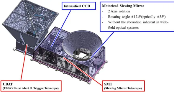
We are currently progressing the UFFO (Ultra-Fast Flash Observatory) Pathfinder mission[2] . UFFO Pathfinder is a space telescope onboard the Lomonosov satellite planned to be launched in November 2011. The advantage of UFFO Pathfinder is extremely fast observation of optical afterglow of Gamma Ray Burst (GRB) in the sub-minute time scale. It consists of two subsystems as shown in Figure 1 i.e. UBAT (UFFO Burst Alert &Trigger Telescope) and SMT (Slewing Mirror Telescope). UBAT is coded mask aperture camera for prompt position detection of GRB with a wide field of view (FOV) of 90.2 x 90.2 degree2. Its detector is a LYSO crystal and 64(8 x 8) MAPMT and it can detect the energy
range of ~5 to ~200 keV.
In our previous study[4], we described the SMT subsystem that is a 100mm Ritchey-Chretien type telescope with a motorized slewing mirror and a 256x256 pixel Intensified Charge-Coupled Device (ICCD) of 22.2μm in pixel size. The SMT field of view is 17 arc min, providing 4 arcsec in pixel resolution. It is further expanded up to 35 degrees by using a motorized slewing mirror. The initial SMT integration showed wavefront error better than 0.05 waves in room temperature while showing no hysteresis characteristic in the static load test up to 60g. In this study, we describe the progress of the UFFO Pathfinder Pre-Flight Model (PFM) SMT subsystem in the space environment tests including thermal cycling and vibration at National Space Organization (NSPO) in Taiwan. In Section 2, the progress and result of the thermal cycling test are summarized. Section 3 deals with the vibration test and results. We describe the MTF performances before and after the space environment test in Section 4 before conclusion in Section 5.
Figure 1. Rendered image of UFFO Pathfinder.
2. THERMAL CYCLING TEST
The UFFO has been exposed total 4 iterative temperature cycles over the range of -30℃ to 40 ℃ (i.e. 70 ℃/Hour in temperature slope) for about 48 hours. The test was performed in the high vacuum level of 10-6 mbar. The thermal
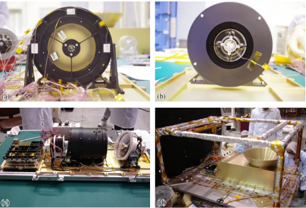
vacuum chamber is SPACE SIMULATOR HVT series from ACS company[5]. Thirteen thermo-couplers were attached to the designated locations on the SMT subsystem including the backsides of primary and secondary mirror to obtain the temperature profile. As examples, Figure 2-(a) and (b) show the positions of thermo-couplers at SMT. Figure 2-(c) shows SMT and UBAT Detector Module (DM) mounted to the base plate, and Figure 2-(d) shows the final eye inspection of the SMT subsystem before starting the thermal cycling test in thermal-vacuum chamber.
Figure 2. (a, b) Locations of thermo-couplers. (c) SMT and UBAT Detector Module (DM) assembled to the base plate. (d) Eye inspection of the SMT subsystem before entering into the thermal-vacuum chamber.
As an example of thermo-couple responses to the thermal loading, the temperature response of M1 and M2 are shown in Figure 3. The red solid line represent the input temperature variation at the bottom plate while the blue dash line is from M1, green dot line from M2, and the violet dashed-dotted line shows the temperature difference between M1 and M2. We note that M1 and M2 thermal responses follow closely to the control temperature variation as predicted, and that the temperature between M1 and M2 ranges from -4.47 to 4.66. We ran a vigorous eye inspection on the instrument after the thermal cycling and found no damage signatures from the opto-mechanical structure, bond lines, electronics boards, wires, connectors and couplers.
3. VIBRATION TEST
After finishing the thermal cycling test, X, Y and Z-axis vibration tests for frequency input of sine sweep, random, and shock were performed, using a shaker made by Ling Electronics company[5]. Figure 4 shows the accelerometers installed to the backsides of M1 and M2 as two examples of many other accelerometers attached to various locations on the instrument. The low sine sweep tests (0.3g from 5 to 2000 Hz) were carried out before and after all other vibration test items. The structural safety check was performed by looking at the frequency responses from the pre and post low sine sweep tests, showing no response differences. This proved the instrument safety with no abnormality in structural integrity.
Figure 4. Examples of accelerometer location for vibration test. (a) M1 backside and (b) M2 backside.
Figure 5. (a) Sine sweep test inputs for X, Y, and Z-axis. (b) Responses of primary mirror to sine sweep test in launch direction (Y-axis), showing the maximum acceleration of 38g at 245Hz.
The sine sweep test inputs and the response results are shown in Figure 5. The sine sweep input condition is up to 9.5 g from 5 to 2000 Hz. Figure 5-(b) shows the maximum response of 38g at 245Hz. The instrument is designed for the safety factor larger than 3 for 60g load, proving that it is stiff enough to withstand against the input stress. The random tests were also performed to the full level (8.76 grms). Figure 6-(a) shows the random test frequency inputs and the M1 response in the launch direction as an example. As shown in Figure 6-(b), it has the peak value at 244 Hz that is similar to 245 Hz from the sine sweep test.
Figure 6. (a) Random test input level for X, Y and Z-axes. (b) Response of primary mirror from random vibration test in launch direction(Y-axis). The peak of spectral density is 2.7g2/Hz at 244Hz.
4. PERFORMANCE EVALUATION
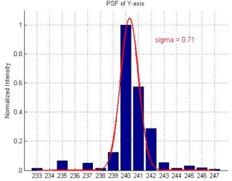
The SMT MTF performance was derived from the measurement of Point Spread Function (PSF) before and after the environment tests. The PSF measurement set-up is illustrated in Figure 7. For the point source, we used parallel rays from the laser interferometer of 6 inches in aperture, and a commercial CCD camera (GRASSHOPPER®GRAS-03K2C/M) made by Point Grey Research, Inc.[6]. The PSF data of X and Y-axis are shown in Figure 8. The bar means normalized intensity and the solid line is Gaussian fitting. The result shows that the 1σ of PSF is 0.88 and 0.71 pixels in each axis.
Figure 8. PSF data of X-axis and Y-axis.
Figure 9 shows the derived MTF data of 0.54 and 0.59 at Nyquist frequency before and after the environment test. The results indicate that the SMT subsystem performance remains stable during the space environment test, providing the confidence to the survivability during the launch and in-orbit operation.
5. CONCLUSION
The UFFO Pathfinder instrument has been subjected to the space environment tests including thermal cycling and vibration test at National Space Organization (NSPO) in Taiwan. Specially, the vibration test results show the response peak at ~ 245 Hz that satisfies the requirement of up to 200 Hz. After the thermal cycling and vibration test, the SMT subsystem shows no damage or unusual signatures. Currently, we are analyzing the measurement data of the Coordinate Measuring Machine (CMM) for any possible structural deformation that can influence the optical performance. The results will be reported elsewhere as it has been made available.
6. ACKNOWLEDGEMENT
This research was supported, in part, by Creative Research Initiatives (RCMST) of MEST/NRF, the World Class University grant no. R32-10130 and National Research Foundation of Korea grant no. 2011-0020672.
REFERENCES
[1] Gehrels, N., et al, “The Swift Gamma-Ray Burst Mission”,ApJ 611(2), 1005-1020(2004)
[2] Park, I. H. et al, “The UFFO (Ultra-Fast Flash Observatory) Pathfinder”, arXiv:0912.0773 (2009)
[3] Panaitescu, A. and Vestrand, W. T., “Taxonomy of gamma-ray burst optical light curves: identification of a salient class of early afterglows”, MNRAS 387, 497-504 (2008)
[4] Jeong, S. et al., “Optical Performances of Slewing Mirror Telescope for UFFO-Pathfinder”, Proc. ICRC 2011, arXiv:1106.3850 (2011)
[5] http://www.nspo.org.tw/2008e/infrastructure/it.htm [6] Imaging camera catalog, Point Grey Research, Inc.