ICCAS2005 June 2-5, KINTEX, Gyeonggi-Do, Korea
1. Introduction
A few years ago, a good Cellular Phone (CP) was simply a well communicating device. Nowadays, communication quality is noting but a necessary condition to be a good CP. A really good CP must include camera, high quality of music, MP3, high LCD quality and etc. Recently, CP is now the most intimate device for a man as well as one of the most important technologies in the IT field, and it is situated in a position of great importance industrially and economically. To produce the best CP in the world, a new technological concept and its advanced implementation technique is required due to the extreme level of competition in the world market.[1][2] The Robot Technology(RT), along with rapid growth of Information Technology(IT), are being developed as the next generation of a future technology. Current robots require advanced technology, such as soft computing, human-friendly interface, interaction technique, speech recognition, object recognition etc. unlike the industrial robots of the past. Therefore, we have developed new technological concept such as the Robotic Cellular Phone(RCP) in which a synergy effect can be generated by merging RT and IT. RCP, CP having personal robot services, will be an intermediate hi-tech personal machine between one CP a person and one robot a person generations.[7][8][9] RCP consists of 3 sub-modules. They are RCP Mobility, RCP Interaction and RCP Integration. For RCP Mobility, human-friendly motion automation and personal service with walking and arming ability are developed. RCP Interaction ability is achieved by modeling an emotion- generating engine and RCP Integration that in miniature integrates the robotic modules into CP is developed with application service programs. By joining intelligent algorithms and CP communication network with the three base modules, a RCP system is constructed. RCP Interaction, which is embedded by the emotion technology of robotics, is the main focus of this paper. It is an interactive emotion system which combines robotic interaction with CP. Through its application, we should be able
to provide CP with multi-emotional signal receiving functionalities. Eventually, CP may become an emotional pet to the human being.
This interaction system, RCP Interaction, consists of various functional modules for multi-emotional signal receiving modes of CP. Interaction between human and environment can be achieved by means of stimulating some of five sensing organs, vision, hearing, taste, smell and touch. Existing CP provides various hearing stimulus such as music and simple touching stimulus such as vibration. We want to develop tactile, olfactory and visual signal receiving modules in order to provide broader and more intimidating touch, taste and vision stimulus thorough CP. They are divided into a tactile, an olfactory and a visual mode. These new signal receiving functions are implemented as separate modules. Moreover, these modules are ready to be linked with communication functions of CP in order to interface between CP and user through a variety of emotional models.
Tactile signal receiving module (Vibration Mode) is designed to stimulate human touching sense in various fashions by reinforcing existing simple vibrating hardware and software. Existing signal receiving device focuses on a simple signaling using a motor having a single vibrating mode. Since music is an important environmental stimulus for human, we think that a mechanical vibration can also play an important role in stimulating human touching sense. For this understanding, we design our tactile signal receiving module to provide a more delicate and profound vibrating stimulus to human touching sense by patterns and beat frequencies which are made by mechanical-vibration conversion of the musical melody, rhythm and harmony.
Olfactory signal receiving module (Aroma Mode) is designed to inform a receiver who the signaler is. That is, it switches control of perfume-injection nozzles which are able to give the signal receiving to the CP-called user through a special kind of smell according to the CP-calling user. Visual signal receiving module (Action Mode) is made by motion control of DC-motored wheel-based system which can
A Development of Multi-Emotional Signal Receiving Modules
for Cellphone Using Robotic Interaction
Yongrae Jung
*, Yonghae Kong
*, Taijoon Um** and Seungwoo Kim
**
Division of Information Technology Engineering, Soonchunhyang University, Korea
**
Department of Mechanical Engineering, Soonchunhyang University, Korea
(Tel : +82-41-530-1369; E-mail : *[email protected])
Abstract: CP (Cellular Phone) is currently one of the most attractive technologies and RT (Robot Technology) is also considered as one of the most promising next generation technology. We present a new technological concept named RCP (Robotic Cellular Phone), which combines RT and CP. RCP consists of 3 sub-modules, RCP Mobility, RCP Interaction, and RCP Integration. RCP Interaction is the main focus of this paper. It is an interactive emotion system which provides CP with multi-emotional signal receiving functionalities. RCP Interaction is linked with communication functions of CP in order to interface between CP and user through a variety of emotional models. It is divided into a tactile, an olfactory and a visual mode. The tactile signal receiving module is designed by patterns and beat frequencies which are made by mechanical-vibration conversion of the musical melody, rhythm and harmony. The olfactory signal receiving module is designed by switching control of perfume-injection nozzles which are able to give the signal receiving to the CP-called user through a special kind of smell according to the CP-calling user. The visual signal receiving module is made by motion control of DC-motored wheel-based system which can inform the CP-called user of the signal receiving through a desired motion according to the CP-calling user. In this paper, a prototype system is developed for multi-emotional signal receiving modes of CP. We describe an overall structure of the system and provide experimental results of the functional modules.
ICCAS2005 June 2-5, KINTEX, Gyeonggi-Do, Korea inform the CP-called user of the signal receiving through a
desired motion according to the CP-calling user.
2.
Multi-Emotional Signal Receiving Modules
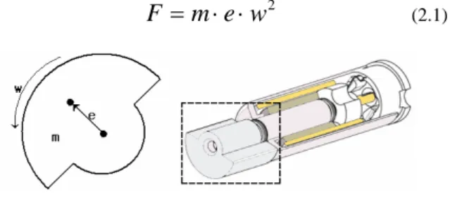
2.1. Tactile Signal Receiving ModeThe tactile Function-Module among Multi-Emotional Signal Receiving Modules conveys mechanically vibrating patterned emotion through human touching sense. This effect can be implemented by transforming musical melody, rhythm and harmony to mechanical-vibrating stimulus of CP vibrating motor. Through CP musical mechanical vibration, a human can feel the identical emotion that he does in hearing music. The heart of this functional module is the control of vibrating motor shown in fig1. The principle of mechanical vibration of motor is mainly due to the rotary force induced by the rotation of eccentric. The rotary force of eccentric rotor can be expressed by equation 2.1. (
m
: Eccentric,e
: Throw of Eccentric,w
: Angular Velocity)2
w
e
m
F
=
⋅
⋅
(2.1)Fig. 1. Configuration of Vibration Motor
The power of vibration motor interacts with the angular velocity because its force is in proportion to a square of angular velocity 2
w . The angular velocity of vibration motor can be derived in the torque equation 2.2. (T: Driving Torque,
J: Inertia Mass, D: Viscous Friction Coefficient, G:gyroscopic Coefficient, f T : Fricton Torque ) f
T
w
G
D
dt
dw
J
T
=
+
(
+
)
+
(2.2) Equation 2.2 is rearranged into equation 2.3 in case that the angular velocity has a constant value in steady state.G
D
T
T
w
const+
f−
=
(2.3)Tf, D , G of the equation 2.3 is determined on the process of mechanical design. Therefore we can know that the driving torque T is in proportion to angular velocity of motor in steady state as shown in equation 2.3.
Through the analysis of the above equations, the rotary power of a vibrating motor is controllable by varying the voltage input to the motor. We can also control the frequency characteristics in a similar way.
Fig. 2. Design Concept of Tactile Module
Fig.2 shows the design concept of tactile function module. The key technique is how to obtain the equivalent vibration from musical melody and rhythm. We propose a shifting conversion method that controls the motor vibrating frequency based on the musical elements as in fig.3.
Fig. 3. Control Block Diagram of Tactile Module Since the tactile function module needs to be embedded into a CP, the motor input voltage is also confined to the CP voltage limit 3.7V. Moreover, most vibration motors have a fixed frequency and can express a simple vibration. It is confirmed in experimental method of this paper that vibration motor can display only 1.2 octaves at most. So it is basically impossible to display the song of a big melody-variation in vibration motor. In case that the melody-variation of a song is too big to implement in the vibration motor, the melody beyond the range is approximately shifted into the melody within the range.
To technically display frequencies of music melody into counterpart of mechanical vibration melody, we convert them through the division of the fixed number. Thereafter, the converted value is applied into the vibration motor using PWM(Pulse Width Modulation) for the efficient driving. To precisely play a song in vibration motor, we implement a feedback control using frequency sensor.
A song consists of melody, rhythm (beat) and chord. Three kinds of factors are implemented in the tactile signal receiving module using three motors which can play different roles. Therefore, a song is perfectly displayed on the vibration system. That is to say, the feeling emotion of a song can be exactly implemented on the tactile signal receiving module.
2.2. Olfactory
Signal Receiving ModeThe olfactory signal receiving module injects
multiple perfumes to stimulate human emotion. Several
medical reports already proved that olfactory stimulus
influences bionic changes. For this reason, medical
treatments using aroma is common as an
alternative medicine.[5]To distinguish CP callers by their perfumes, this module controls the injection of perfumes to be dependent to CP caller just like current caller-dependent music signals. Consequently, a receiver is able to feel the caller-dependent aromatic emotion. For example, the CP of a person injects an intimate perfume when a friend calls him while it does a tense perfume when his superior calls him.
There are several ways to inject perfume materials such as use of a mechanical or an electrical nozzle that controls the injection of perfumes and a fan that controls the flow of perfumed air. Among these, we prefer to use electrical nozzles since they are more adequate for digital equipments like CP.
We design the olfactory signal receiving module to inject multiple perfumes simultaneously by transforming electrical signals to control multiple micro nozzles as shown in fig. 4.
ICCAS2005 June 2-5, KINTEX, Gyeonggi-Do, Korea
Fig. 4. Design Concept of The Olfactory Module The block diagram that controls the multiple micro nozzles is illustrated in fig. 5. To build our experimental flat form, using commercially available parts is more desirable in cost as well as timeliness. Micro inkjet cartages are selected for this purpose. Electrical signal is applied to the micro nozzle. And, in turn, the nozzle builds up heats by the electrical energy. Finally, the material in the nozzle is injected. We use an inkjet cartage that has 12 micro nozzles. We can drive these 12 nozzles separately or in groups as necessary.
Fig. 5. Control Block Diagram of The Olfactory Module Human olfactory organ feels the emotion by inhaling the perfumed air. The air needs to be circulated because the feeling keeps on as long as there remains the air. This effect may cause interference among several perfumes. We try to minimize this negative effect by promptly closing the nozzle entrance right after injection.
2.3. Visual Signal Receiving Mode
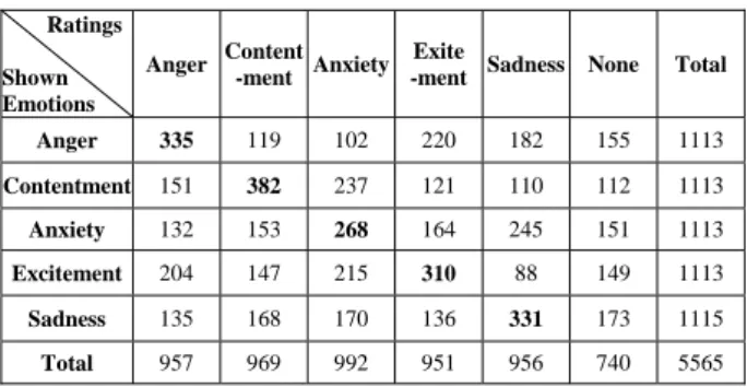
The visual signal receiving module is to make an independent motion by the control of the two wheels attached on the battery of CP. The movement of an object such as a dance can emotionally influence to the humans. A specific action and movement can give rise to the corresponding emotion. Recently, such a relation of movement and emotion was verified in field of robotics. That was confirmed through a variety of movement of mobile robot. It was explained in the research results of Tomoko Kato and Takaya Arita that a movement pattern of mobile robot gives rise to the corresponding emotion for the humans. The research result is shown in table 1. [6][13]
Table 1. Human Ratings of Emotion
Ratings Shown Emotions Anger Content -ment Anxiety Exite
-ment Sadness None Total Anger 335 119 102 220 182 155 1113 Contentment 151 382 237 121 110 112 1113 Anxiety 132 153 268 164 245 151 1113 Excitement 204 147 215 310 88 149 1113 Sadness 135 168 170 136 331 173 1115 Total 957 969 992 951 956 740 5565
(Bold-Type: The Most Frequently Associated Emotions)
For the wheel-based movement of the visual signal receiving module, we should be able to find out the current position of the RCP(Robotic Cellular Phone) and be able to control its specific motion. Therefore, we need a kinematical analysis on the RCP movement.
In this implementation of the wheel-based navigation, we used a robot model with two wheels. It is one of the simplest ways of implementing wheel-based robot, and its kinematical diagram is shown in Fig. 3. We can derive a kinematical model of RCP from this diagram. RCP speed at the contact point of the wheel with the floor under the non-slipping condition is given in Equation (2.4).
Fig. 6. Visual Module System with Two Wheels
L L R R r
V
rV
= ω , = ω(2.4)
L r L L R L RV
V
ω ω ω = − = −(2.5)
2 2 L R L RV
V
v= + =γω +ω(2.6)
L Rω
ω
,
: Angular velocities of wheelsv
: Linear velocity of RCP,ω
: Angular velocity of RCPr
: Radius of the wheel,L
: Distance between two wheelsTherefore, the relationship between
[
]
T y x PP θ and
[
]
Tv ω can be expresses as a kinematical formula:
⎥
⎦
⎤
⎢
⎣
⎡
⎥
⎥
⎥
⎦
⎤
⎢
⎢
⎢
⎣
⎡
=
⎥
⎥
⎥
⎦
⎤
⎢
⎢
⎢
⎣
⎡
ω
θ
θ
θ
v
P
P
y x1
0
0
sin
0
cos
(2.7)Note that in Equation (2.7) we have two motors for RCP control, but we have three degrees of freedom for the direction and angle to the destination. This is because we have an extra steering wheel not associated with any motor. Therefore, a constraint occurs when we want to change RCP’s current posture into a new one. However, if we take advantage of the non-slipping condition, which implies the vertical velocity to the wheel is 0 at the contact point of wheel with the floor, we can derive a non-holonomic constraint.
Fig. 7 shows a mechanical design of visual module attached by 2 wheels connected by 2 DC-motors independently controlled. This system uses reduction gears for the high torque of DC motors and bevel gear for the simple transfer of torque.
ICCAS2005 June 2-5, KINTEX, Gyeonggi-Do, Korea
Fig 7. A Mechanical Design of Visual Module The control system is explained in Fig. 8. Velocity and position feedback control of DC motor is designed by using micro encoder sensor. A desired motion, which is decided according to calling user, is realized by control of 2 wheels.
Fig. 8. Control Block Diagram of Visual Module
3. Experiments
3.1. Implementation of Tactile Mode System
The tactile mode system needs 3 DC-motors which play independent role mapped to 3 major factors of a song (Melody, Rhythm and Harmony). The optimally designed result of vibration motors and mechanical coupling system is shown in the center of Fig. 9. The appearance system was fabricated by rapid prototype machine. The left part of Fig. 9 is a electronic system which consists of main control unit, vibration motor driver unit and RF wireless communication unit. The right part shows a experiment scene which test an emotional signal receiving by the tactile mode
Fig 9. The Implemented System of Tactile Module Fig. 10 shows the emulation system for wireless communication of CP. We used a wireless RS-232C for the wireless communication method. The called CP is RCP designed in this paper and the calling CP is a personal computer.
Fig. 10. Experimental Setup of Tactile Module
Table 2 is the converted frequencies and the corresponding input voltages of 1 octave. We confirmed through a variety of experiments that vibration motor can display only 1.2 octaves at most. So it is basically impossible to display the song of a big melody-variation in vibration motor. In case that the melody-variation of a song is too big to implement in the vibration motor, the melody beyond the range was approximately shifted into the melody within the range. That is a weak point in the implementation of tactile mode system.
Table 2. Vibration Motor of Frequency Bandwidth Octave Frequency (Hz) Voltage(V) Input
Do 65.405 0.37 Re 73.416 0.63 Mi 82.407 0.74 Fa 87.307 0.93 Sol 97.999 1.22 Ra 110 1.39 Si 123.47 1.59 Do 130.813 2.04 Re 146.832 3.33
3.2. Olfactory Signal Receiving Mode
A real configuration of olfactory signal receiving module is shown in Fig. 11. In this paper, 3 small-sized cartridges, which each consists of 11 micro nozzles, was used for the olfactory mode of CP. The left part of Fig. 11 shows a optimal design of three packs of micro nozzles and the appearance system. The center part is a electronic system of main control unit, switching driver unit of micro-nozzles and RF wireless communication unit. The right part shows a experiment scene which test an emotional signal receiving, which is mapped into the calling user, by the olfactory mode,.
Fig. 11. Implemented System of Olfactory Module The experiment results of olfactory signal receiving module is shown in Fig. 12. The driving signal and switching signal of micro nozzles are explained in the Fig. 12. The driving devices for micro nozzle used P-channel FET and switching power TR. The amount and frequency of perfume-injection are controlled by using switching control of micro nozzles.
ICCAS2005 June 2-5, KINTEX, Gyeonggi-Do, Korea
3.3. Visual Signal Receiving Mode
The center and left part of Fig. 13 shows a actual design of 2 wheels, 2 DC-motors, reduction gear, bevel gear, steering wheel and the appearance system. The radius of wheel is 4.5mm and diameter of small-sized motor is 2.0mm. The right part shows an electronic system of main control unit, motor driver unit and RF wireless communication unit
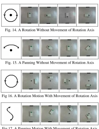
Fig. 13. The Implemented System of a Visual Module A various kinks of movement (action) patterns are shown in Fig. 14 – Fig. 17. Fig. 14 is a simple rotation without movement of rotation axis. That is unexciting and pleasant signal receiving. Fig. 15 is a panning motion without movement of rotation axis. That is exciting and pleasant signal receiving. Fig. 16 is a rotation motion with movement of rotation axis. That is unexciting and unpleasant signal receiving. Fig. 17 is a panning motion with movement of rotation axis. That is exciting and unpleasant signal receiving.
Fig. 14. A Rotation Without Movement of Rotation Axis
Fig. 15. A Panning Without Movement of Rotation Axis
Fig 16. A Rotation Motion With Movement of Rotation Axis
Fig 17. A Panning Motion With Movement of Rotation Axis
4. Conclusion
The CellPhone application of robotic interaction system, RCP Interaction, consists of various functional modules for
multi-emotional signal receiving modes of CP. In this paper, We developed the functional modules divided into a tactile, an olfactory and a visual mode. The tactile signal receiving module (Vibration Mode) was designed by patterns and beat frequencies which were made by mechanical-vibration conversion of the musical melody, rhythm and harmony. The olfactory signal receiving module (Aroma Mode) was designed by switching control of perfume-injection nozzles which were able to give the signal receiving to the CP-called user through a special kind of smell according to the CP-calling user. The visual signal receiving module (Action Mode) was made by motion control of DC-motored wheel-based system which could inform the CP-called user of the signal receiving through a desired motion according to the CP-calling user..
Finally, we confirmed a good performance of multi-emotional signal receiving modules of RCP though the experiment results. In the future, we will develop the automatic switching system of these signal receiving modes according to the exist environment of CP.
ACKNOWLEDGMENTS
This research was supported by the Ministry of Commerce, Industry and Energy of the Korean Government through the BIT Wireless Communication Devices Research Center at SoonChunHyang University.
REFERENCES
[1] Fujita, M., "Digital creatures for future entertainment robotics,"
Proceedings of IEEE International Conference on Robotics and Automation, pp. 801-806 vol. 1, 2000
[2] Breazeal (Ferrell), C. "A motivational system for regulating
human-robot interaction, " In Proceedings of AAAI 98. Madison,
WI, 1998.
[3] T.Shibata and K.Tanie, "Creation of Subjective Value through
Physical Interaction between Human and Machine," Proc. of
The Fourth Int. on Artificial Life and Robotics (AROB 4th '99), Vol.1, pp.20-23 (1999).
[4] N. Kubota, Y. Nojima, N. Baba, F. Kojima and T. Fukuda,
"Evolving Pet Robot with Emotional Model," Proc. of the 2000
Congress on Evolutionary Computation (CEC '00), Vol. 2, pp. 1231-1237 (2000).
[5] Yoon, S.-Y. 2000. "Affective Synthetic Characters," Ph D. diss.
Department of Brain and Cognitive Sciences, Massachusetts Institute of Technology. Forthcoming.
[6] Yoon, S.-Y., Blumberg, B. M., and Schneider, G. E.,
"Motivation driven learning for interactive synthetic characters,"
Proceedings of Autonomous Agents, 2000
[7] Seungwoo Kim, Jaeil Choe, "A Study on The new Technological Concept of Robotic Cellular Phone(RCP)", International Journal of Intelligent Material Systems and Structures, pp. , 2005.
[8] Jaeil Choe, Seungwoo Kim, "A Study on Infra-Technology of Robotic Cellular Phone", Proceedings of IEEE/RSJ International Conference on Intelligent Robots and Systems, pp. 3571-3576, Sept., 2004.
[9] Seungwoo Kim, Jaeil Choe, "A Study on Infra-Technology of
RCP Interaction System, Proceedings of International
Conference on Control, Automation and Systems, pp. 1121-1125, Aug., 2004.
[10] Kline, C. and Blumberg, B. "The Art and Science of Synthetic
ICCAS2005 June 2-5, KINTEX, Gyeonggi-Do, Korea
AI and Creativity in Entertainment and Visual Art, Edinburgh, Scotland, 1999.
[11] Isla, D., Burke, R., Downie, M., and Blumberg, B., "A layered
brain architecture for synthetic creatures," Proceedings of the
International Joint Conferences on Artificial Intelligence, pp. 1051-1058, 2001
[12] Izard, C. E. (1979). The maximally discriminative facial movement scoring system. Unpublished manuscript, University of Delaware.
[13] Miwa, H., Umetsu, T., Takanishi, A., and Takanobu, H., "Robot
personality based on the equation of emotion defined in the 3d
mental space," Proceedings of IEEE International Conference