ICCAS2005 June 2-5, KINTEX, Gyeonggi-Do, Korea
1. INTRODUCTION
Making a map by global sensor information is a mainstream in mobile robot's navigation. The global sensor is for getting a absolute coordinate. There are some global sensors but the most common ones are ultrasonic range and laser range finders. The ultrasonic range finder is a very-cheap sensor, but it has high beam-width, therefore it has low lateral resolution. While the laser range finder has highly collimated beams, so it overcomes the former finder's problem [1].
The laser range finder in which the laser source has a continuous wave can achieve precise range measurements at high speeds, and with adequate component choice, at low coasts [1].
Most techniques to improve the signal-to-noise(S/N) ratio in a measurement rely on the principle that the average value of the noise is zero, but the value of the signal has some finite one. The longer the time period for averaging the noise, the smaller its value of the noise becomes. Thus, an improvement in S/N ratio comes at the expense of longer observation time. One of most useful devices for improving the S/N ratio in experiments is the Lock-in amplifier. Therefore, the experiments described in this paper were done for the Lock-in amplifier.
2. SYSTEM CONFIGURATION
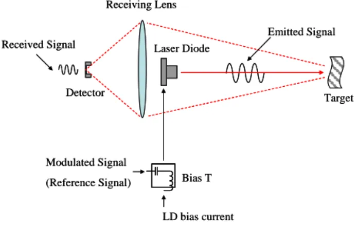
The Fig. 1 shows our system configuration. We used continuous wave signal to drive LD (Laser Diode). The main idea calculating the distance is detecting phase shift between reference signal and detected one by photo detector.
2.1 Optical and electrical elements
For the laser emitter we used a semiconductor laser (Lanics, QL65D5SA). It can provide output powers up to 5mW. And the PIN photo diode(Thorlabs, DET110) was also used. The DET series detectors are compact, versatile and high speed (about 50MHz) optical detectors. The aspherical lens(Thorlabs) for collimation and the camera lens (Nikon, D-52mm) for receiving reflected light were used .
Laser Diode
Bias T
LD bias current from ACC Circuit Modulated Signal (Reference Signal) Received Signal Target Receiving Lens Emitted Signal Detector Laser Diode Bias T LD bias current from ACC Circuit Modulated Signal (Reference Signal) Received Signal Target Receiving Lens Emitted Signal Detector
Fig. 1 System Configuration
To make constant bias current a commercial LD driver(Wavelength Electronics, LDD-400-1P) was used. This low noise driver offer excellent current stability in constant current mode or power stability in constant power mode. It's modulation input's 3dB bandwidth is described as DC to 2MHz in constant current mode in datasheet [4]. But output signal can not follow when modulation frequency is higher than tens of kHz. Therefore, we used bist-T(Minicircuits, PBTC-1GW) to mix modulation signal with DC bias.
2.2 Equipment
In this paper, a commercial Lock-in amplifier (Ametek, SIGNAL RECOVERY Model 7280) was used. It represents a significant advance in the application of DSP technology in the design of a Lock-in amplifier. Until now, limitations in the available semiconductor devices have restricted the operating frequency range of such instruments to at most a few hundred kHz. The model 7280, with its use of the latest technology, extends this limit to 2 MHz. What is more, it does this without compromising any other important specifications [3].
The Laser Range Finder for the Mobile Robot Navigation using a Lock-in
Amplifier
Hee-Sun Yoon*, Myung-Kwan Shin* and Kyi-Hwan Park
**Department of Mechatronics, GIST(Gwangju Institute of Science and Technology), Gwangju, Korea *(Tel : +82-62-970-2411; E-mail: [email protected], [email protected])
** (Tel : +82-62-970-2391; E-mail: [email protected])
Abstract: Map building is the most important thing for the mobile robots navigation. It requires specific vision system such as
CCD camera, range finding system, and many other things. Laser range finder has highly collimated beams can be obtained easily, thus achieving lateral resolution. Laser Diode is used for a continuous laser source. The Automatic Current Control Circuit and the Bias-T is used for mix AC signal with DC bias. This signal is used for driving Laser Diode. The main idea of the calculating distance is detecting phase shift between reference signal and detected signal by photo detector. For the signal processing, the Lock-in amplifier system is addressed in this paper. We used a diffused reflected beam to detect phase shift in this system. But this beam is minuteness signal so it can be easily buried in nose. Lock-in amplifier is used to measure the amplitude and phase of signals which are buried in noise.
Keywords: Range Finder, Laser Diode, Modulation, Lock-in Amplifier
ICCAS2005 June 2-5, KINTEX, Gyeonggi-Do, Korea
2.3 LD driving circuit
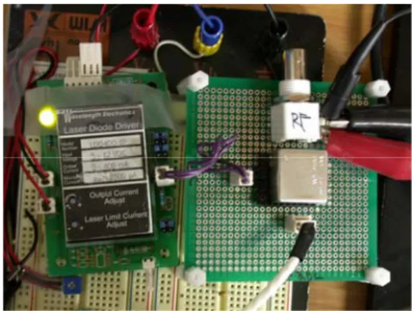
The Fig. 2 shows LD driving circuit. Left side is for LDD-400-1P, commercial LD driver and another side for bist-T for modulation signal.
The amplitude of the modulating current injected in the LD can be adjusted to obtain maximum modulation depth in order to stay within LD operating range. If its amplitude is larger than LD operating current range then LD is easily done. The Fig. 3 shows the best suited driving signal.
Fig. 2 LD Driving Circuit
The potentiometer is used to control bias current and that avoids current spikes through the laser diode during transients. The current spikes might shorten the operation life of LD and even destroy it. Increasing the bias current slowly by adjusting the potentiometer makes both turn-on and turn-off transients safe. Bias current Modulated signal Operating Range Bias current Modulated signal Operating Range
Fig. 3 LD Driving Signal
3. PRINCIPLE OF LOCK-IN AMPLIFIER
Lock-in amplifier is used to measure the amplitude and phase of signals buried in noise. It achieves this by acting as a narrow bandpass filter which removes much of the unwanted noise while allowing through the signal which is to be measured.
The frequency of the signal to be measured and hence the passband region of the filter is set by a reference signal, which has to be supplied to the lock-in amplifier along with the unknown signal. The reference signal must be at the same
frequency as the modulation of the signal to be measured [2]. Lock-in measurements require a frequency reference. Typically an experiment is excited at a fixed frequency (from an oscillator or function generator) and the lock-in detects the response from the experiment at the reference frequency. In the diagram below, the reference signal is a square wave at frequency ωsig . This might be the sync output from a function generator. If the sine output from the function generator is used to excite the experiment, the response might be the signal waveform shown below. The signal is
) sin( sig sig
sig t
V ω +θ where Vsig is the signal amplitude, sig
ω is the signal frequency, and θsig is the signal’s phase. Lock-in amplifiers generate their own internal reference signal usually by a phase-locked-loop locked to the external reference. In the diagram below the external reference, the lock-in’s reference and the signal are all shown. The internal reference is Vrefsin(ωreft+θref).
Fig. 4 Reference signal, Input signal, Lock-in signal The lock-in amplifier amplifies the signal and then multiplies it by the lock-in reference using a phase-sensitive detector or multiplier. The output of the phase sensitive detector is simply the product of two sine waves.
(1) The phase sensitive detector output is two AC signals, one at the difference frequency (ωsig−ωref) and the other at the sum frequency (ωsig +ωref).
If the phase sensitive detector output is passed through a low pass filter, the AC signals are removed. In the general case, nothing will be left.
However, if ωsig equals ωref ,
) 2 cos( 2 1 ) cos( 2 1 sig ref sig ref sig ref sig ref out V V V V t V = θ −θ − ω+θ +θ , (2) where ωref =ωsig =ω.
If output is passed through a low pass filter, right term } ) cos{( 2 1 sig ref sig ref sig refV t V ω +ω +θ +θ − } ) cos{( 2 1 sig ref sig ref sig ref V t V ω −ω +θ −θ = ) sin( )
sin( ref t ref Vsig sigt sig ref
V out
V = ω +θ ω +θ
ICCAS2005 June 2-5, KINTEX, Gyeonggi-Do, Korea
including 2ω is removed. Therefore, if ωsig equals ωref ,
the difference frequency component will be a DC signal. In this case, the filtered phase sensitive detector output will be
) cos( 2 1 ref sig sig ref out V V V = θ −θ . (3)
This output signal Vout is a DC signal proportional to the signal amplitude,Vsigcosθ where θ=(θsig−θref).
θ is the phase difference between the signal and the lock-in reference oscillator. By adjusting θref we can make
θ equal to zero, in which case we can measure Vsig. ) cos( 2 1 ref sig sig ref out V V V = θ −θ VrefVsig 2 1 = , (4) where θsig =θref , i.e. cos(θsig−θref)=cos0=1. Therefore, unknown Vsig become to known value because Vref is known. Vsig is signal amplitude.
Conversely, if θ is 90 , there will be no output at all. A o lock-in with a single phase sensitive detector is called a single-phase lock-in and its output is Vsigcosθ.
This phase dependency can be eliminated by adding a second phase sensitive detector. If the second phase sensitive detector multiplies the signal with the reference oscillator shifted by 90 , i.e. o Vrefsin(ωreft+θref +90o), its low pass filtered output will be
) 90 cos(
2
1 − − o
= ref sig sig ref
out V V V θ θ ) 90 cos( 2 1 − o = VrefVsig θ . (5) Now we have two outputs, one proportional to cosθ and the other propotional to sinθ. If we call the first output
X and the second Y , θ cos sig V X= , (6) θ sin sig V Y= . (7) These two quantities represent the signal as a vector relative to the lock-in reference oscillator. X is called the ‘in-phase’ component and Y the ‘quadrature’ component. This is because when θ=0, X measure the signal while Y is zero.
By computing the magnitude R of the signal vector, the phase dependency is removed.
sig V Y X R= 2+ 2 12 = ) ( (8) R measures the signal amplitude and does not depend upon the phase between the signal and lock-in reference. A dual-phase lock-in has two phase sensitive detectors, with reference oscillators 90 apart, and can measure o X ,Y and R directly. In addition, the phase θ between the signal and lock-in reference, can be measured according to,
) / ( tan−1 Y X = θ . (9)
4. EXPERIMENTS RESULT
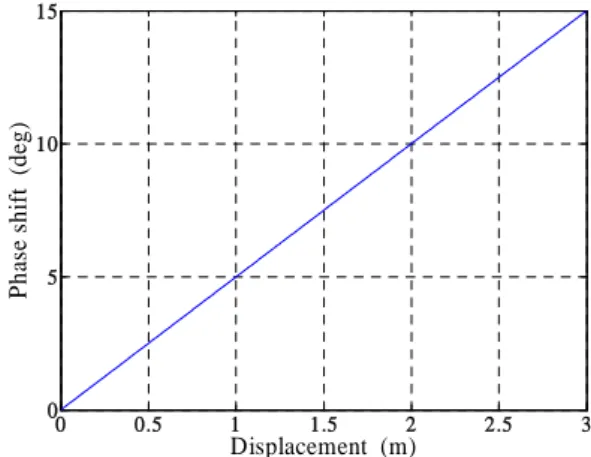
4.1 Theoretical analysisThe modulating signal frequency is 2MHz because the bandwidth of the lock-in amplifier is 2MHz. For a modulating signal of 2MHz the distance covered for a full 360 phase o shift is 150m.
f c =
λ (10) Where c=3×10⁸m/s (the velocity of light),
Hz
f =2×10⁶ , then λ is 150m, and this, considering that the light has to travel to the target and back, and that the lock-in amplifier used can detect phase shifts between 0 and o
o
180 , gives us a maximum range of 37.5m. Therefore, difference of 1o means the displacement of 0.2m.The Fig. 5 shows that. 0 0.5 1 1.5 2 2.5 3 0 5 10 15 Displacement (m) P h as e s h if t (d eg )
Fig. 5 Theoretical Relationship
4.2 Experiments result
The Fig. 6 shows our experiments result. As the range increase from its minimum value, the phase shift also increased about 1o/0.2m . At the range of 1-3 m displacement, the linear relationship was observed but at 0.5m displacement range we could not obtain flawless signals because of screening the reflected light by LD emitter. 0 0.5 1 1.5 2 2.5 3 0 5 10 15 20 25 30 Displacement (m) P h as e s h if t (d eg )
Fig. 6 Experiments Result
ICCAS2005 June 2-5, KINTEX, Gyeonggi-Do, Korea
5. CONCLUSION AND FURTURE WORKS
In our experiments we obtained the signals through the reflection marks. But in a real environment the reflection rates from the all walls are not homogeneous like reflection mark. Also it is impossible to attach the reflection marks for all walls.
Thus the optical component that can collect the scattered lights of reflection will be necessary. And in this case the signals will be weaker. To treat the signals collected by the detector the filter that obtain the pure reference frequency signals must be designed.
To apply to robot's navigation a mechanical device that can scan the distances instead of measuring the 1 point distance must be added. We can suggest the method obtaining the map using the scanning mirror and rotary encoder from SICK and LMS series.
REFERENCES
[1] Lamela, H and Garcia, E, “A low power laser rangefinder for autonomous robot applications,” Industrial Electronics, Control, and Instrumentation, 1996., Proceedings of the 1996 IEEE IECON 22nd International Conference , Vol. 1, pp. 161-167, 5-10 Aug. 1996.
[2] Jaeheon Jeong,, “Digital Signal Processing of a Lock-in Amplifier for AFM application,” Thesis for the Degree of M.S., Gwangju Institute of Science and Technology, pp. 20-35, 2005.
[3] SIGNAL RECOVERY Model 7280 Wide Bandwidth DSP Lock-in Amplifier, “Instruction Manual”, Ametek Advanced Measurement Technology, INC, 2002.
[4] LDD P Series Laser Diode Drivers, “User’s Manual”, Wavelength Electronics, www.teamwavelength.com