2019 ⦽ǎႊᔍᖒ⠱ʑྜྷ⦺⫭ ⇹ĥ⦺ᚁݡ⫭ םྙ᧞Ḳ
243
A Convertible Plasma Torch System for Treatment of Low and Intermediate Level
Radioactive Waste
Jun-Ho Seo*, Junseok Nam, In-Mok Yang, Min-Gyu Choi, Mi-Yeon Lee, Hyo-Jeong Kim, Ho-Sang Lee, and Shi-Young Yang
Chonbuk National University, 567 Baekje-daero, Deokjin-Gu, Jeonju, Jeollabuk-Do, Republic of Korea
*
1. Introduction
As reported in many other papers [1-4], plasma torch systems are promising for volume reduction of decommissioning wastes of nuclear power plants. By melting the radioactive waste drums directly without complicated processes for sorting or pretreating, plasma torch systems can provide a unified melting process for both of metallic and non-metallic wastes. In addition, the melted slugs can be obtained in non-leachable glass form, which are preferable in LILW disposal facility. Most of all, plasma melting route is expected to produce excellent volume reduction ratio compared with other technologies such as super-compaction.
In this work, we report the development of a convertible plasma torch system applicable to the volume reduction of low and intermediate level radioactive waste. For this purpose, a hollow electrode plasma torch with inter-electrodes was designed and tested in reverse polarity. By forcing the arc column to extend as long as the inter-electrode length, this type of plasma torch can increase plasma power with the arc voltage at fixed arc currents, allowing for high plasma enthalpy. In addition, double cathodes were employed for the designed plasma torch. By reducing the arc current per electrode, we expect that this introduction of double cathodes can help in extending the service life time of the electrodes. Finally, a plasma torch operation system was constructed and the performance test was carried out at the power level of 0.3~1.2 MW
2. Design of Plasma Torch System
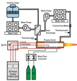
Fig. 1 shows a schematic diagram of a plasma torch system used in this study. As shown in this figure, the designed plasma torch system primarily consists of a 1.5 MVA class DC power supply (750 A x 2 kV), a hollow electrode plasma torch, a gas supply system and a water supply system to cool down the plasma torch. For the torch performance test, the flow rates of plasma forming gases and the cooling water were controlled by mass flow meters and a water pump with an inverter controller. In addition, the temperature risings in cooling water were measured by K-type thermocouple installed at inlet and outlet of the coolant line. From these instruments for measurement of the operation parameters, torch efficiency defined as the ratio of exit plasma enthalpy to the input power can be measured together with the V-I characteristics as a basic performance data of the torch.
Fig. 1. A Schematic diagram of the hollow electrode plasma torch system with inter-electrode and reversed
244
2019 ⦽ǎႊᔍᖒ⠱ʑྜྷ⦺⫭⇹ĥ⦺ᚁݡ⫭םྙ᧞Ḳ Fig. 2. A cross-sectional view of hollow electrode plasma torch with inter-electrode and reversed polarity dischargestructure.
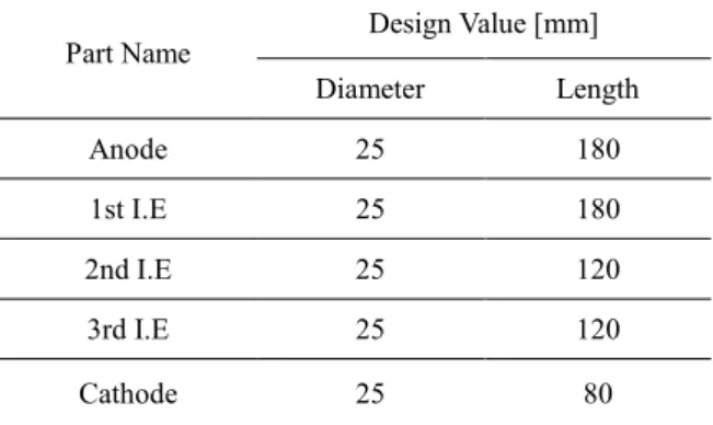
Table 1. Design values of the hollow electrode plasma torch with inter-electrode and reversed polarity discharge structure Part Name Design Value [mm] Diameter Length Anode 25 180 1st I.E 25 180 2nd I.E 25 120 3rd I.E 25 120 Cathode 25 80
Fig. 2 illustrates the cross-sectional view of the hollow electrode plasma torch with inter-electrodes employed in the plasma torch system of Fig. 1. In this figure, the presented plasma torch has three inter-electrodes, designated as 1st I.E., 2nd I.E. and 3rd I.E., respectively, between hollow cathode and cylindrical anode. In order to investigate the effects of inter-electrodes length, performance tests were conducted with increasing the number of inter-electrodes from 1 to 3. In Fig. 2, the arc column between front and rear electrodes is also presented together with the electrical connection diagram for reversed polarity discharge structure setting the rear and front electrodes as anode and cathode, respectively. For easy ignition, the 1st inter-electrode was used as a pilot cathode in this work. After ignition, the arc column was transferred to the front electrode and the electrical connection to the inter-electrode was disconnected. The number of inter-electrode can be increased by inserting additional one between first inter-electrode and front cathode.
In this work, the performance tests were carried out for the plasma torch with single inter-electrode and two inter-electrodes, respectively, in order to
check the effect of inter electrode number. The details on the design parameters of the plasma torch are listed in Table 1.
REFERENCES
[1] D.G. Cacucci (Ed.), Handbook of Nuclear Engineering volume V, 3253-3420 (2010).
[2] S.C. Park, D.U. Kim, M.H. Kim, J.H. Seo, O.B. Yang, J. Kor. Phys. Soc. 63, 1746-1754 (2013). [3] S.L. Camacho, Pure Appl. Chem. 60, 619 (1988). [4] G. J. Hanus, T. J. Stahl and S. L. Camacho, US