Evaluation of Fatigue Crack Initiation for Volumetric Flaw in Pressure Tube
Sung-nam Choi,a Hyun-joo Yoo,a
a Korea Electric Power Research Institute, Nuclear Power Lab., 103-16 Munji-Dong, Yuseong-Gu, Daejeon, Korea
1. Introduction
CAN/CSA–N285.4-94 requires the periodic inservice inspection and surveillance of pressure tubes in operating CANDU nuclear power reactors [1]. If the inspection results reveal a flaw exceeding the acceptance criteria of the Code, the flaw must be evaluated to determine if the pressure is acceptable for continued service.
Currently, the flaw evaluation methodology and acceptance criteria specified in CSA-N285.05-2005 [2], “Technical requirements for in-service evaluation of zirconium alloy pressure tubes in CANDU reactors” . The Code is applicable to zirconium alloy pressure tubes.
The evaluation methodology for a crack-like flaw is similar to that of ASME B&PV Sec. XI, “Inservice Inspection of Nuclear Power Plant Components”. However, the evaluation methodology for a blunt volumetric flaw is described in CSA-N285.05-2005 code.
The object of this paper is to address the fatigue crack initiation evaluation for the blunt volumetric flaw as it applies to the pressure tube at Wolsong NPP.
2. Methods and Results
2.1 Technical Requirements for the volumetric flaw If the inspection results reveal a volumetric flaw, the licensee shall demonstrate that fatigue crack initiation will not occur during the evaluation period. General fatigue crack initiation evaluation is followed:
- determining the time of flaw formation - determining the operating transient history
- characterizing fatigue crack initiation for blunt flaw - calculating the peak alternating von Mises effective
stress
- evaluating the cumulative usage factor 2.2 Postulated volumetric flaw of pressure tube
Normally, the shape and the size of a blunt flaw are determined on the replication results. To evaluate fatigue crack initiation, a postulated volumetric flaw is used. The geometry of a blunt flaw is followed:
- blunt flaw length : 2.8 mm - with : 1.0 mm
- depth: 0.3 mm
- flaw root radius: 0.6 mm
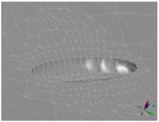
The finite element of a postulated blunt flaw is modeled by IronCAD, which is showed in figure 1.
Figure 1. Finite element model of a volumetric flaw 2.3 Pressure Tube Dimension and Material
The predicted pressure tube dimensions at the end of the pressure tube design life of a total of 210,000 EFPH were used in the evaluation. Pressure tube wall thinning is occurred due to creep and corrosion. The finite element model of a pressure tube is followed:
- inner diameter: 108.9 mm - wall thinness: 3.65 mm - pressure tube length: 200.0 mm - material: Zr 2.5% Nb
The finite elements of the postulated volumetric flaw are modeled on the inside surface of the pressure tube. 2.4 Alternating Peak Stress Analysis
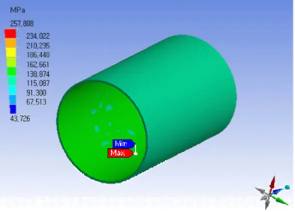
To evaluate the fatigue crack initiation, the applied alternating von Mises effective peak flaw-tip stress shell be calculated. There are two ways to calculate the alternating peak stress. The first way is based on stress intensity factor. The other is based on elastic stress concentration factor in this paper. To use the elastic stress concentration factor, the finite element anlysis is obtained from the results of DesignSpace program. 10MPa pressure is loaded on the surface of the inner pressure tube and the volumetric flaw. Maximum and Minimum von Mises stress results are showed in figure 2.
The elastic stress concentration factor, kt, is calculate by eq. 1. 81 . 1 759 . 142 808 . 257 Stress Mises von Nominal tip flaw the on Stress Mises von = = − = MPa kt (1)
Transactions of the Korean Nuclear Society Autumn Meeting Busan, Korea, October 27-28, 2005
Figure 2. Von Mises peak stress on a blunt flaw The maximum range (∆σn
)
of the nominal stress iscalculated for all service level A and B load transients. The alternating von Mises effective peak stress is calculated using the following equation (2) proposed by the Code.
n t k
S = 4350. ∆σ (2) 2.5 Cumulative Usage Factor Evaluation
All service level A and B load transients are considered from the pressure tube stress analysis design report of Wolsong NPP. For each type of stress cycle, the value of alternating von Mises effective peak flaw-tip stress is calculated
Usage factors are calculated by
i i i N n U = (3) where
ni = total number of load cycles for cycle type i Ni = allowable number of load cycle from the fatigue
crack initiation evaluation curve for blunt flaws in the Code
Ui= total number of load cycle types i
The cumulative usage factor, U, is calculated using
m U U U U= 1+ 2+⋅⋅⋅+ (4) where
m= total number of load cycle types
Preventing the fatigue crack initiation for all service level A and B transient loads is demonstrated when the cumulative usage factor is less than 1.0.
The cumulative usage factor concerned with all the design service level A and B load transients at Wolsong NPP is 0.07. The calculated cumulative usage factor is less then 1.0.
3. Conclusion
The evaluation of fatigue crack initiation is demonstrated that the pressure tube with a postulated volumetric flaw meets the criteria of the CSA code. All pressure tube design transients at Wolsong NPP are
used in the evaluation and a very small volumetric flaw is modeled and analyzed. The cumulative usage factor for the postulated blunt flaw is less then 1.0.
Fatigue crack for the postulated volumetric flaw is therefore predicted not to initiate up to the end of pressure tube design life.
REFERENCES
[1] CAN/CSA Code N285.4-94, “Periodic Inspection fo CANDU Nuclear Power Plant Components”, 1994. Dec. [2] CSA Code N285.8-05, “Technical requirements for in-service evaluation of zirconium alloy pressure tubes in CANDU reactors”, 2005. Jun.
[3] “Assessment of Flaws found in Wolsong NGS Unit 1 fuel Channels during the February 1994 In-service Inspection Program,” Report No. A-NFC-94-67-P, Ontario Hydro Technologies, 1994. Feb.
[4] "Wolsung-234 Nuclear Power Plant Fuel Stress Analysis”, 86-31100-SR-001, AECL, 1996, Jan
[5] ASME B&PV, "Analysis of flaws", Sec. XI, App. A, 1995. Jul.
[6] “월성 1 호기 압력관 재질검사 수행채널 현황”, 한국전력공사, 1998
[7] 최성남, 김형남, “월성 3 호기 압력관 건전성 평가 보고서”, 한전 전력연구원, 2003, 3.