Development of a Liquid Transportation System for the KSTAR ICRF
Jae Sung Yoon1, Bong Guen Hong1, and Dong Chul Park21
Korea Atomic Energy Research Institute(KAERI) PO Box 105, Yuseong, Daejeon, Korea305-600
2
Chungnam National University, 220 Gung-Dong, Yuseong-Gu, Daejeon, 305-764, Korea
1. Introduction
The liquid matching systems of the KSTAR Ion Cyclotron Resonance Frequency (ICRF) system consist of a liquid stub tuner and a liquid phase shifter. The liquid matching systems contain a liquid between the inner and outer conductors of the coaxial transmission line. By changing the liquid level instead of shifting the electric short-end, the phase of the wave can be shifted based on the difference between the RF wavelength in the liquid and gas due to the different relative dielectric constants [1]. A liquid transportation system of the liquid stub tuner for ICRF matching system has been fabricated, accompanying control circuits for the pump and the valves have also been designed and fabricated. As compared to the previous liquid transportation system and control circuits, the newly constructed system has more simple structure of the liquid lines than previous one.
2. Fabrication of a liquid transportation system and controller for the liquid matching systems
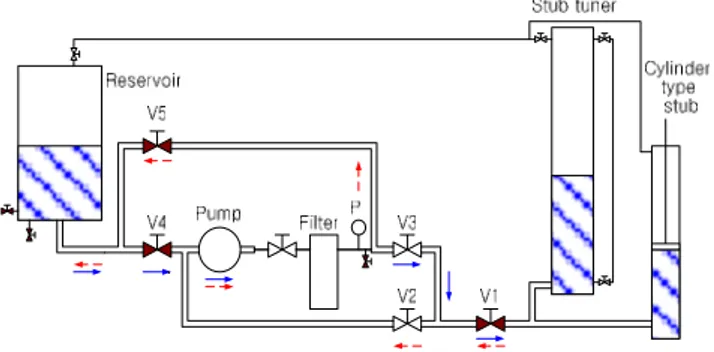
The schematic diagram of the liquid transportation system for the liquid matching system was shown in figure 1. A solid arrow shows the liquid path from reservoir to liquid stub tuner or/and cylinder type stub, and a dotted arrow shows the liquid path from liquid stub tuner to reservoir. The operation of the Valve 1, Valve 3 and Valve 4 are open when the liquid is transferred from reservoir to liquid stub tuner, and Valve 1, Valve 2 and Valve 5 are open reversely operated. Valve 2 and valve 3 are open at the stop status [2]. The liquid transportation systems of the liquid matching system consist of three independent systems for the liquid stub tuner and liquid phase shifter which has two separated liquid lines respectively. A set of the liquid transportation system (LTS) and control circuit have been fabricated and tested. The main parts of the LTS are composed reservoir, pump, magnetic valves and oil filer to remove the trash in the liquid lines. The path of the liquid between the reservoir and liquid stub tuner was designed to pass the filter to get rid of the trash in the LTS. The capability of the liquid transfer of the pump is 3m3 / hr, and it will have the liquid raising velocity of 2.5 cm / sec for the liquid stub tuner.
The liquid transfer capacity of the Pump was shown in figure 2, and MHI 203 was used in fabricated LTS. The control circuit of the LTS controls pump and cylinder type stub, the one control transportation liquid between the reservoir and the liquid stub tuner to find matching condition roughly and the other control the liquid transportation between the liquid stub tuner and cylinder type stub to adjust the fine matching condition and feedback control. The picture of the fabricated control circuit and LTS were shown in figure 3 and figure 4.
Figure 1. A schematic diagram of the liquid line structure of the liquid matching system
Figure 2. A characteristic graph of the liquid pump
Transactions of the Korean Nuclear Society Autumn Meeting Busan, Korea, October 27-28, 2005
Figure 3. Fabricated control circuit of the liquid transportation system
Figure 4. Fabricated liquid transportation system
3. Conclusion
A liquid transportation system of the liquid stub tuner for ICRF matching system has been fabricated, accompanying control circuits for the pump and the valves have also been designed and fabricated. The new designed liquid transportation system has independent liquid transfer line for the liquid stub tuner and phase shifter respectively. As compared to the previous liquid transportation system and control circuits, the newly constructed system has more simple structure of the liquid lines than previous one.
It will be installed ICRF Liquid Matching Systems and will be used to matching condition by controlling the liquid level.
REFERENCES
[1] Yoon J. S., Bae Y. D., Kwak J. G., and Hong B. G., 2004 J. Korean Phys. Soc. 44, 1203.
[2] Yoon J. S., Bae Y. D., Kwak J. G., and Hong B. G., 2005 vol. 1 Proceedings of the Korean Nuclear Society Spring Meeting, Jeju, Korea, May 2005.