Vol. 16, No. 4, December 2016, pp. 318-322 http://dx.doi.org/10.5391/IJFIS.2016.16.4.318
Design of Vectored Sum Defuzzification
Based Fuzzy Logic System for Hovering
Control of Quad-Copter
Hyun-Ho Yoo and Byung-Jae Choi
Department of Electronics Engineering, Daegu University, Gyeongsan, Korea
Abstract
A quad-copter or quad rotor system is an unmanned flying machine having four engines, which their thrust force is produced by four propellers. Its stable control is very important and has widely been studied. It is a typical example of a nonlinear system. So, it is difficult to get a desired control performance by conventional control algorithms. In this paper, we propose the design of a vectored sum defuzzification based fuzzy logic system for the hovering control of a quad-copter. We first summarize its dynamics and introduce a vectored sum defuzzification scheme. And then we design a vectored sum defuzzification based fuzzy logic system. for the hovering control of the quad-copter. Finally, in order to check the feasibility of the proposed system we present some simulation examples.
Keywords: Fuzzy logic control, Defuzzification method, Quad-copter, Hovering control, Rule table
Received: Dec. 11, 2016 Revised : Dec. 12, 2016 Accepted: Dec. 13, 2016 Correspondence to: Byung-Jae Choi ([email protected])
©The Korean Institute of Intelligent Systems
cc
This is an Open Access article dis-tributed under the terms of the Creative Commons Attribution Non-Commercial Li-cense (http://creativecommons.org/liLi-censes/ by-nc/3.0/) which permits unrestricted non-commercial use, distribution, and reproduc-tion in any medium, provided the original work is properly cited.
1.
Introduction
A quad-copter or quad rotor system is an unmanned flying machine having four engines, which their thrust force is produced by four propellers. It has been known as a drone of an unmanned aircraft. It was firstly used only for the military purpose. However, its use is widely expanded to parcel delivery service at a big open market in the United States. It is also used at aviation photography area and etc. Its many successful applications also lead to the activation of the research for a good quad-copter system. Its nonlinearity is utilized by even a good model for intuitive verification of the performance of the designed control system.
Quad-copter system is flying to up and down, and left and right using four propellers. It is also a typical example of a nonlinear system. Its mechanism consists of four motions: altitude, roll, pitch, yaw motions. In [1], rigorous dynamic model of a quad-copter was obtained both in reference and body frame coordinate systems. A controller using a disturbance observer was also proposed for robust hovering control. A modified sliding surface technique was applied to the conventional adaptive sliding mode control in [2]. Authors added an integral term to the sliding surface for preventing initial chattering and high gain. In [3], authors proposed how to decrease computational complexity with appropriate control performance for real time and online applications. Another paper [4] showed that the additional set of 4 control inputs actuating the propeller tilting angles yields full actuation to the quadrotor posi-tion/orientation in space and it allowed to behave as a fully-actuated flying vehicle.
Figure 1.A coordinate system for the quad-copter.
control system to improve the hovering control performance of the quad-copter. We first introduce a new defuzzification method called vectored sum scheme. And we then design a fuzzy logic control system using the vectored sum defuzzifica-tion scheme for the hovering control of the quad-copter. Finally, in order to check the feasibility of the proposed system we present some simulation examples.
The rest of the paper is organized as follows. In Section 2, we describe the summary of a dynamic model of the quad-copter. The introduction of a vec-tored sum defuzzification scheme and the design of a fuzzy logic system for its hovering control are pre-sented in Section 3. In Section 4, we present simulation examples and their usefulness.
2.
Dynamics of Quad-Copter
A coordinate system for the quad-copter is roughly depicted in Figure 1 [1, 2, 5, 6].
The position p of the quad-copter and its Eulers angle η in an inertial frame are expressed as Eqs. (1) and (2), respectively.
p = [x y z]T, (1)
η = [φ, θ, ψ]T. (2)
The velocity v and angular velocity ω in a body fixed frame are expressed as Eqs. (3) and (4), respectively.
v = [vx vy vz]T, (3) ω = [ωx ωy ωz]T. (4) Now we can derive the following equations.
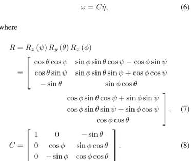
˙ p = Rv, (5) ω = C ˙η, (6) where R = Rz(ψ) Ry(θ) Rx(φ) =
cos θ cos ψ sin φ sin θ cos ψ − cos φ sin ψ cos θ sin ψ sin φ sin θ sin ψ + cos φ cos ψ
− sin θ sin φ cos θ
cos φ sin θ cos ψ + sin φ sin ψ cos φ sin θ sin ψ + sin φ cos ψ
cos φ cos θ , (7) C = 1 0 − sin θ
0 cos φ sin φ cos θ 0 − sin φ cos φ cos θ
. (8)
From Eqs. (5) and (6), we can get the following equations. ¨
p = R ˙v + ˙Rv = R( ˙v + ω × v), (9) ˙
ω = C ¨η + ˙C ˙η. (10)
We consider a control force F and a gravity Fgas the external forces, and a control moment Q and a gyro effect QGas the external moments.
F = [0 0 F1+ F2+ F3+ F4], (11)
Fg= mRTg0, (12)
Q = [ l(F4− F2) l(F3− F1) τ1− τ2+ τ3− τ4]T, (13) QG= ω × IRΩG= [0 0 Ω1−Ω2+ Ω3− Ω4]T, (14) where m is a mass of the quad rotor and g0is a gravity vector of g0= [0 0 − g]T. Fi= kiΩi2
(kiis a thrust) and Ωiis the angular velocity of the i-th rotor.
Thus, we can summarize its dynamics as the following equa-tions.
¨
p = g0+ 1
mRF, (15)
¨
η = (IC)−1(Q − I ˙C ˙η − C ˙η × (IC ˙η + IRΩG). (16)
3.
Design of Fuzzy Logic Control System
Now we describe about a fuzzy logic system to be designed for the hovering control of quad-copter. It was confirmed that a fuzzy logic system can lead good control performance to the application to highly nonlinear plants.Figure 2.Typical structure of a two-input fuzzy logic control system.
Figure 3.Membership functions for vectored sum defuzzification scheme.
is the type that composed of single output variable and two input variables which are an error and its derivative. It was known as two-input fuzzy logic control system and is similar to the control principle of the conventional PI controller or PD controller. Figure 2 shows a typical structure for a two-input fuzzy logic control system.
In Figure 2, Saturation is a kind of normalization. That is, two input fuzzy variables are firstly normalized by the Saturation block and then applied to the fuzzy logic controller (FLC).
As we know, the FLC consists of a fuzzifier, inference engine, rule base, and defuzzifier. The defuzzifier determines a crisp value from a fuzzy variable through an appropriate defuzzifica-tion method.
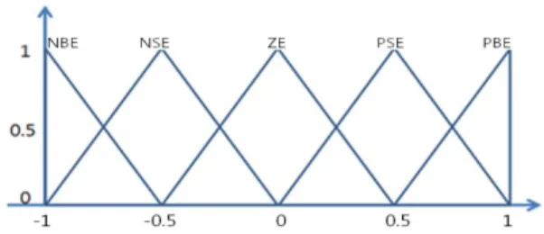
We here introduce a new defuzzification method called vec-tored sum scheme. There are so many defuzzification methods including the center of gravity (COG) and the simplified COG (centroid). They all have their own advantages and disadvan-tages.
A vectored sum defuzzification method is as follows. Con-sider a semicircle of radius 1 like Figure 3. Membership func-tions (Mf(1), Mf(2), ..., Mf(n)) are angles (θ(1), θ(2), ..., θ(n)) between x-axis and them, respectively.
From the inferred results, mf1,mf2, ... and, mfnthe output membership function, Vmf i(xi, yi) is expressed by the
follow-Figure 4.Membership functions for the fuzzy logic control system (eeta).
ing equation.
Vmf i(xi, yi) = Vmf i(l (i) ∗ cos θ (i) , l (i) ∗ sin θ (i)) . (17) Now we can express a vector by the following equation.
u (x, y) = n X i=1
Vmf i(xi, yi). (18)
Then the final crisp output, u0 is calculated by the equation.
u0 = arctan 2(x, y). (19)
This is more intuitive and less complex.
We now design a fuzzy logic control system using a vec-tored sum defuzzification scheme for the quad-copter. The quad-copter needs two control systems of the position and the hovering, respectively. We here design a two-input fuzzy logic system for controlling the hovering of the quad-copter. We des-ignate it as Hovering FLC. The hovering means a self-sustaining maneuver whereby a fixed position is maintained relative to a spot on the surface of the earth. That is, we can get a sta-ble flying motion by a hovering control of roll, pitch, and yaw angles.
We set two input variables for Hovering FLC to an error (eeta) between the current angle and the desired angle of the quad-copter and its derivative (deeta). We also set its output variable to the body torque (du) of the quad-copter. All mem-bership functions for input and output variables are set to types of isosceles triangles like Figure 4. The meaning of each mem-bership function is presented in Table 1.
Now we set control rules for Hovering FLC of the quad-copter as Table 2. As we know it from Table 2, two input variables (eeta, deeta) and single output variable (du) are com-posed of all five membership functions. The meaning of five membership functions for the output variable is as follows: NB:
Table 1.Definition of fuzzy membership functions for hovering FLC Angle error (eeta) Change of angle error
(deeta)
Positive Big PBE 1 Positive Big PBEE 1 Positive
Small PSE 0.5
Positive
Small PSEE 0.5
Zero ZE 0 Zero ZEE 0
Negative
Small NSE -0.5
Negative
Small NSEE -0.5 Negative Big NBE -1 Negative Big NBEE -1
Table 2.Fuzzy control rule table for Hovering FLC deeta
eeta
NBEE NSEE ZEE PSEE PBEE
PBE Z PS PS PB PB
PSE NS Z PS PS PB
ZE NS NS Z PS PS
NSE NB NS NS Z PS
NBE NB NB NS NS Z
Negative Big, NS: Negative Small, Z: Zero, PS: Positive Small, PB: Positive Big.
4.
Simulation Results and Conclusions
In order to compare the control performance of the proposed fuzzy logic control system, we do a computer simulation. Here the mass (m) and the length (l) are 2.2 kg and 0.3 m, respec-tively. And we set the initial and final angle (φ, θ, ϕ) to (0, 0, 0) and (0, 0, 1), respectively.
We use Mamdanis Min-Max inference and the vectored sum and centroid defuzzification methods to compare their control performance.
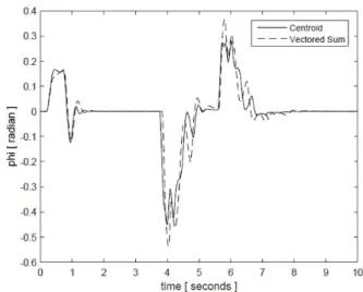
The hovering of a quad-copter is controlled by roll, pitch, and yaw angles. These simulation results are presented in Figures 5-7. In the simulation, we changed the position of a quad-copter to another position at near 4 sec.
As we know them from Figures 5-7, the control performances are almost the same in two cases. Furthermore, the computa-tional time of the vectored sum defuzzification method is faster than that of the centroid method. As a result, the proposed defuzzification method, vectored sum scheme is useful for the design of the fuzzy logic control system.
Figure 5.Simulation results of Hovering FLC (φ).
Figure 6.Simulation results of Hovering FLC (θ).
Conflict of Interest
No potential conflict of interest relevant to this article was reported.
Acknowledgements
This research was supported by the Daegu University Research Grants.
References
[1] J. Kim, M. S. Kang, and S. D. Park, “Dynamic modeling and robust hovering control of a quadrotor VTOL aircraft,” Journal of Institute of Control, Robotics and Systems, vol. 14, no. 12, pp. 1260-1265, 2008. http://dx.doi.org/10.5302/ J.ICROS.2008.14.12.1260
[2] D. H. Choi, “Design and control of a quad-rotor UAV,” M.S. thesis, Korea Advanced Institute of Science and Technology, Daejeon, Korea, 2009.
[3] F. Fakurian, M. B. Menhaj, and A. Mohammadi, “Fuzzy controller design for quadrotor UAVs using minimal con-trol input,” Indian Journal of Scientific Research, vol. 1, no. 2, pp. 157-164, 2014.
[4] M. Ryll, H. H. Bulthoff, and P. R. Giordano, “A novel over-actuated quadrotor unmanned aerial vehicle: modeling, control, and experimental validation,” IEEE Transactions on Control Systems Technology, vol. 23, no. 2, pp. 540-556, 2015. http://dx.doi.org/10.1109/TCST.2014.2330999 [5] G. W. Yang, “Dynamic modelling of quad-rotor UAV,”
Available http://blog.daum.net/pg365/64
[6] G. W. Yang, “Control and simulation of quad-rotor UAV,” Available http://blog.daum.net/pg365/65
[7] A. Bousbaine, M. H. Wu, and G. T. Poyi, “Modelling and simulation of a quad-rotor helicopter,” in Proceedings of
6th IET International Conference on Power Electronics, Machines and Drives, Bristol, UK, pp. 1-6, 2012. http: //dx.doi.org/10.1049/cp.2012.0318
[8] Y. C. Choi and H. S. Ahn, “Nonlinear control of quadrotor for point tracking: actual implementation and experimen-tal tests,” IEEE/ASME Transactions on Mechatronics, vol. 20, no. 3, pp. 1179-1192, 2015. http://dx.doi.org/10.1109/ TMECH.2014.2329945
[9] S. Kang, J. Choi, and T. Jin, “Performance enhancement of the attitude estimation using small quadrotor by vision-based marker tracking,” Journal of Korean Institute of Intelligent Systems, vol. 25, no. 5, pp. 444-450, 2015. http://dx.doi.org/10.5391/JKIIS.2015.25.5.444
[10] H. H. Yoo and B. J. Choi, “Design of simple-structured fuzzy logic systems for segway-type mobile robot,” Inter-national Journal of Fuzzy Logic and Intelligent Systems, vol. 15, no. 4, pp. 232-239, 2015. https://doi.org/10.5391/ IJFIS.2015.15.4.232
Hyun-Ho Yoo received his B.S. from the De-partment of Electronic Engineering, Daegu University, in 2014. Now he is a Master degree student at Daegu University. His re-search interests include robot control and in-telligent systems.
Tel: +82-53-850-4432, Fax: +82-53-850-6619 E-mail: [email protected]
Byung-Jae Choi is a professor at the College of Information, Communication, and Com-puter Engineering, Daegu University. He re-ceived the Ph.D. degree in Electrical Engi-neering from KAIST, Korea. Currently, his main research interests include intelligent control and systems. Tel: +82-53-850-6633, Fax: +82-53-850-6619