Unified design approach for single- and 3-phase input air conditioning systems using SiC devices
Simon Kim*, Swaminathan Balasubramaniasarma^, Kwokwai Ma
#and Daewoong Chung*
*Infineon Technologies Korea, ^Infineon Technologies India, #Infineon Technologies Hong Kong
Abstract
This paper examines the approach, enabled by using SiC power devices, to unify the inverter design for central air conditioning (CAC) system for both single- and 3-phase input, and reduce the PFC inductor size to be PCB-mountable. By using SiC- instead of Si-diode in PFC stage, it is possible to increase the switching frequency from 16kHz to 60kHz to reduce the required PFC inductance from 0.93mH to 0.25mH, thus enable PCB-mounting of inductor. With the next step of using 1200V SiC MOSFET instead of Si-IGBT, the DC link voltage can be boosted from 311Vdc to 550Vdc in PFC stage, allowing the inverter and compressor used in 3-phase input CAC be used for single-phase input as well. Furthermore, using SiC MOSFET in inverter stage can further reduce total loss system total loss to 200.8 W. Simulation and experimental results are presented in the paper.
1. Introduction
Air conditioning system may be classified into room air conditioning system (RAC) and commercial air conditioning system (CAC). Maximum power level of RAC is about 4 kW, and power level of CAC is higher than RAC in general. The circuit of RAC with rated power range under 1kW consists of single-phase rectifier and 3-phase inverter. For rated power range over 1.5 kW, RAC will have additional single boost PFC circuit. Input voltage for RAC is mostly single phase AC (110V/220V), while for CAC the inputs can be either single phase (110V/220V) or 3-phase (380V/440V) at nominal line frequency of 50/60Hz. For CAC with single-phase AC input, the power circuit must include PFC stage [2], and in these applications single PFC and interleaved PFC topologies are popular [2] and the cascaded stage is usually 3-phase inv3]erter. For CAC with phase input, the circuit composes of phase rectifier and 3-phase inverter only. In addition, capacitor-less CAC will have brake chopper circuit to regulate DC link voltage. CAC with rated power over 7kW only use 3-phase input, while at 7kW rated power both single phase input and 3-phase input would be used.
In power electronics applications, compact dimension and system cost reduction are always the design goals to pursue. SiC power devices play an important role to achieve these design goals due to its low power losses, especially substantial reduction of switching loss at high switching frequency. Because of these advantages, SiC power devices have already been used in solar inverter application to achieve the highest efficiency. However, in traditional domains like drive and CAC system, they are still finding their place slowly.
This paper specifically focuses on CAC system, which requires not only efficiency improvement, but also reduction of size, weight and cost. The design approach of 7kW CAC will be reviewed with improved design proposals based on SiC power devices.
2. Review of existing design approaches
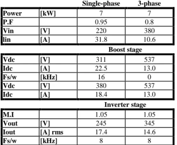
The typical specifications of a 7kW CAC with single-phase input and with 3-phase input are shown in Table 1. The typical circuits of 7kW CAC inverter with 3-phase input and single-phase input are shown in Fig. 1. For phase input, the circuit is composed of 3-phase input rectifier and 3-3-phase inverter, while for single-3-phase input the circuit is composed of interleaved PFC and 3-phase inverter. Power loss simulation with 3 phase input is performed with Vdc = 550V considering input voltage variation and parameter settings shown in Table 2. Inverter stage is operated at switching frequency Fsw=8kHz, which may also be reduced to 4kHz to reduce inverter power loss.
Single-phase 3-phase Power [kW] 7 7 P.F 0.95 0.8 Vin [V] 220 380 lin [A] 31.8 10.6 Boost stage Vdc [V] 311 537 Idc [A] 22.5 13.0 Fs/w [kHz] 16 0 Vdc [V] 380 537 Idc [A] 18.4 13.0 Inverter stage M.I 1.05 1.05 Vout [V] 245 345 Iout [A] rms 17.4 14.6 Fs/w [kHz] 8 8
Table 1. Estimated operating condition of 7kW CAC with single phase input Vin = 220Vac, and 3-phase input Vin = 380Vac
(A)
(B)
Fig. 1 7kW CAC circuit: (A) with 3-phase input and (B) with single phase input with interleaved PFC
Parameter Range
Input Voltage (3 phase input)
380 (nominal),
342 (Low line) ~ 418 (High line) Maximum voltage in
DC link capacitor
537 (Nominal), 484 (Low line) ~ 592 (High line), DC bus capacitor rating should be rated ~ 650V Ripple voltage in
capacitor 10% Average voltage in
DC link capacitor
510 (Nominal),
459 (low line) ~ 561 (High line) DC bus capacitance
[1]
1064 F (Nominal),
1310 F (Low line) ~ 880F (High line) Table 2. Parameter settings for 7kW CAC with 3-phase input
Fig. 2 Power loss simulation with PLECS
In this study, the latest 7th generation IGBT module FP30R12W2T7_B11 [3], which is rated for Tvjop=175℃ during overload, is used. PLECS is used for simulation with datasheet value of FP30R12W2T7_B11 as thermal model data.
205
Table 3 provides the loss simulation results for 7kW CAC with 3-phase input. A simple three phase rectifier is used in this architecture. Loss estimation is done for the inverter with switching frequencies Fsw at 4kHz and 8kHz respectively. From this table, the inverter loss at Fsw = 4kHz has the lower loss around 46 W compared to the loss at Fsw=8kHz. Due to reduction in switching frequency, the inverter loss can be reduced up to 24%. However, inverter waveform at Fsw = 4kHz has inferior THD compared to 8kHz, with higher audible noise.
Part Item Device loss Qty Sub total unit
Rec Diode 6.9 6 41.4 W
PFC Switch 0 W
Diode 0 W
Inv (Fsw Switch 20.4 6 122.4 W
= 8kHz) Diode 4.5 6 27 W
Sum Total loss 190.8 W Part Item Device loss Qty Sub total unit
Rec Diode 6.9 6 41.4 W
PFC Switch 0 W
Diode 0 W
Inv (Fsw Switch 12.7 6 76.2 W
= 4kHz) Diode 4.5 6 27 W
Sum Total loss 144.6 W Table 3. 7kW CAC with 3-phase input Vin = 380Vac at Fsw=8kHz and 4kHz respectively.
For 7kW CAC with single-phase input as shown in Fig. 1(B), power losses in single phase input rectifier, PFC and inverter must be calculated together. In this study, the 30A 600V IGBT module FB30R06W1E3 [4] is used, which consists of single phase input rectifier and 3-phase inverter circuit. 30A 600V discrete IGBT IKW30N60H3 [5] and 30A 600V Rapid Diode IDW30C65D1 [6] are used as IGBT and diode respectively for PFC loss simulation in interleaved topology. PFC power losses is calculated at Fsw=16kHz.
Part Item Device loss Qty Sub total Unit
Rec Diode 14.9 4 59.6 W
PFC (Fsw= Switch 22.4 2 44.8 W
16kHz) Diode 16.6 2 33.2 W
Inv (Fsw= Switch 16 6 96 W
8kHz) Diode 3.8 6 22.8 W
Sum Total loss 256.4 W Part Item Device loss Qty Sub total Unit
Rec Diode 14.9 4 59.6 W
PFC (Fsw= Switch 22.4 2 44.8 W
16kHz) Diode 16.6 2 33.2 W
Inv (Fsw= Switch 13.6 6 81.6 W
4kHz) Diode 3.1 6 18.6 W
Sum Total loss 237.8 W Table 4. 7kW CAC with single phase input Vin = 220Vac at Fsw=8kHz and 4kHz respectively, and PFC at Fsw=16kHz
Refer to Tables 3-4, the total power loss of 7kW CAC with single-phase input with inverter Fsw = 4kHz is higher than that with 3-phase input at Fsw = 8kHz by 47 W. Although both types of 7kW CAC inverter can use the same heatsink, single phase input version have to use two additional heavy inductors with inductance of several mH’s. Such heavy inductors cannot be mount on PCB. Therefore, the design of single phase input version should be improved.
3. PFC design review
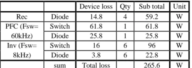
If SiC diode is being used to replace Si diode in the PFC stage, IGBT turn-on loss Eon can be substantially reduced due to extremely low reverse recovery current, and higher frequency operation will thus be possible. In this study, 30A 1200V SiC diode IDW30G120C5B [7] and 50A IGBT IKW50N65WR5 [8] are used in single PFC. Table 5 shows the simulation results with Fsw=60kHz in PFC stage. With nearly 4 times of switching frequency, the total loss is only slightly higher than using Si diode at Fsw =16kHz by 9 W.
Device loss Qty Sub total Unit Rec Diode 14.8 4 59.2 W PFC (Fsw= Switch 61.8 1 61.8 W 60kHz) Diode 25.8 1 25.8 W Inv (Fsw= Switch 16 6 96 W 8kHz) Diode 3.8 6 22.8 W sum Total loss 265.6 W Table 5. 7kW CAC with single phase input Vin = 220Vac & SiC Diode in PFC
Assuming an inductor ripple current of 20%, for 16kHz operation the required PFC inductance is calculated to be 0.93mH. For 60kHz operation, inductance can be reduced to 0.25mH, as shown in Fig. 3. With such reduction of PFC inductance, it becomes possible to mount the inductor on PCB directly.
Inductance at Fsw = 16kHz 0.931 mH (220V, Nominal)-Recommended 0.783 mH (187V, Low line), 1.03 mH (253V, High line)
Fig. 3 Required PFC inductance vs Fsw with Vdc = 380Vdc
4. Boost DC link voltage to unified inverter & compressor
While using SiC diode in PFC stage for CAC with single-phase input bring the advantage of smaller PFC inductor, both the DC link voltage and inverter output voltage of single-phase input CAC are different from that of 3-phase input CAC, and thus requires different types of inverter and compressor.
In general, 600V IGBT and diode are used for PFC stage in CAC with single-phase input. If 1200V SiC MOSFET and SiC diode are used instead, it will be possible to boost the DC link voltage from 311Vdc to 550Vdc with Fsw = 60kHz. At such DC link voltage, CAC with single-phase input can use the same type of inverter and compressor as used with 3-phase input CAC, which will highly simplify manufacturing cost and effort.
To verify this approach, 45mΩ 1200V SiC MOSFET IMW120R045M1 [9] and 30A 1200V SiC diode IDW30G120C5B are used in PFC. Simulation results are shown in Table 5. While DC link voltage is boosted from 311Vdc to 550Vdc, total loss is just increased by 18 W compared to 600 V inverter system with Vdc = 380Vdc and PFC Fsw = 60kHz. Rectifier loss is slightly reduced due to bigger diode chip, while inverter loss is increased by 26 W (from 96 W and 122.4 W) due to 1200V IGBT is being used.
Device loss Qty Sub total Unit
Rec Diode 14.1 4 56.4 W
PFC Switch 54.7 1 54.7 W (Fsw=60kHz) Diode 23.1 1 23.1 W Inv Switch 20.4 6 122.4 W (Fsw=8kHz) Diode 4.5 6 27 W Sum Total loss 283.6 W Table 5. 7kW CAC with single phase input Vin = 220Vac using 1200V SiC Diode and SiC MOSFET in PFC stage, and Vdc = 550Vdc
-With DC link voltage increased from 380Vdc to 550Vdc, duty cycle of the PFC switch will be increased from 0.1815 to 0.4345, and opposite for diode. In general, switching loss will increased with increased duty cycle. However, with the use of SiC MOSFET and SiC Diode, the loss in PFC stage (PFC switch loss + PFC Diode loss) is reduced by around 10 W, at higher DC link voltage of 550Vdc.
The required PFC inductance at Vdc = 550Vdc can be reduced to around 0.3mH at Fsw = 60kHz, from 1.24 mH at Fsw = 16kHz, as shown in Fig. 4. Inductance (with Fsw= 16kHz) 1.24 mH (220V, Nominal) - Recommended 0.975 mH (187V, Low line), 1.51 mH (253V, High line)
Fig. 4 Required PFC inductance vs Fsw withVdc = 550Vdc 5. Using SiC MOSFET in CAC inverter stage
For 7kW CAC using 35A Si-IGBT module & Vdc = 550Vdc as shown in Table 5, the highest power loss comes from the inverter switch at 122 W. If SiC MOSFET module is used instead, this part of power loss can be reduced significantly. To verify this approach, SiC MOSFET module FS45MR12W1M1 [10] with six 45mΩ 1200V SiC MOSFET’s is used for simulation. When the inverter stage is operated at Fsw = 8kHz, power loss of switch is reduced from 122.4 W to 47.4W, and system total loss to 200.8W. When switching frequency is being doubled to Fsw = 16kHz in inverter stage, SiC MOSFET’s power loss is just increased by 21W to 68.4W, as shown in Table 6.
Device loss Qty Sub total Unit Rec Diode 14.1 4 56.4 W
PFC SW 54.7 1 54.7 W
(Fsw= 60kHz) Diode 23.1 1 23.1 W
Inv SW 7.9 6 47.4 W
(Fsw= 8kHz) Diode 3.2 6 19.2 W Sum Total loss 200.8 W Device loss Qty Sub total Unit Rec Diode 14.1 4 56.4 W
PFC SW 54.7 1 54.7 W
(Fsw= 60kHz) Diode 23.1 1 23.1 W
Inv SW 11.4 6 68.4 W
(Fsw=16kHz) Diode 3.4 6 20.4 W Sum Total loss 223 W Table 6. 7kW CAC power loss with SiC MOSFET for inverter part at Vdc = 550Vdc
Further size reduction can be possible by integrating the gate driver and SiC MOSFET module into intelligent power module (IPM) as presented in [11]
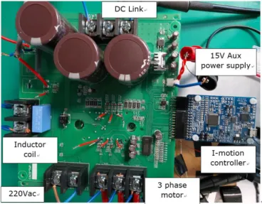
6. Experimental verification by evaluation board
An inverter board with SiC diode IDW30G120C5B, 50A discrete IGBT and 30 A 600 V PIM module (Rectifier + Inverter), has been developed for evaluation as shown in Fig.5.
Fig. 5 Evaluation board: power board and controller board
Gate driver IC’s 1ED44175 and 6ED2230S12T are used for PFC and 3-phase inverter stages respectively. 1ED44173 has ±5% over-current protection accuracy, ± 2.6 A output current and negative current feedback. 6ED2230S12T is an 1200V SilicononIsolator (SOI) level shift gate driver IC and can be operated with -100V negative transient voltage for 700ns. Also, it has ±5 % over-current protection accuracy and can drive 1200V 35A IGBT module. The EVAL-M3-102T controller board with IMC102T-F064 controller is used [12]. This controller can control both single PFC and inverter.
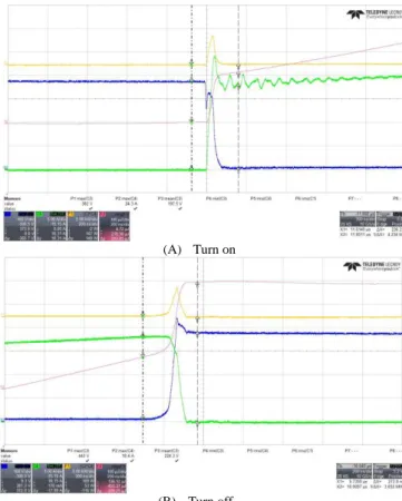
IGBT switching losses Eon and Eoff in PFC stage are measured by double pulses test at Ic = 18.3A. When SiC diode is used instead of Si diode, Eon of Si IGBT is reduced by nearly 55%, from 483.5µJ to 213.85 µJ, as shown in Fig. 6 & 7. When SiC MOSFET instead of Si IGBT is used together with SiC diode, total switching loss (Eon+Eoff) can be reduced from 533.1 µJ to 299.1µJ as shown in Fig. 8, which is a 43.8% loss reduction in PFC stage.
(A) Turn on
(B) Turn off
Fig. 6 IGBT power loss in PFC stage using 50A Si IGBT & 40A Si Diode. Blue: VCE, Green: IC. Eon= 483.5µJ & Eoff = 384.28 µJ
-(A) Turn on
(B) Turn off
Fig. 7 IGBT power loss in PFC stage using 50A Si IGBT & 30A SiC Diode. Blue: VCE, Green: IC. Eon= 213.85µJ & Eoff = 319.25 µJ
(a) Turn on
(b) Turn off
Fig. 8 SiC MOSFET power loss in PFC stage using 45mΩ SiC MOSFET & 30A SiC Diode. Blue: VDS, Green: ID. Eon= 173.73µJ & Eoff = 125.33 µJ
The PFC stage can be operated up to 60kHz, as shown in Fig.9. This board is being tested at maximum 3kW, with Fsw = 24kHz for PFC and 12kHz for inverter, as shown in Fig. 10.
Fig. 9 Wizard GUI for IMC102T-F064 i-motion controller with Fsw = 60kHz [13].
Fig. 10 Test in actual air conditioning system
7. Conclusion
In this paper, the design approach of 7kW CAC is reviewed. 7kW CAC has single phase input and 3-phase input versions. While both 7kW CAC versions can use the same heatsink, the single-phase input version must use two additional heavy inductors with inductance of several mH’s, which cannot be mounted to PCB.
Using discrete 30 A SiC diode and 50A IGBT, it is possible to increase the switching frequency of PFC stage from Fsw=16kHz to 60kHz to reduce the required inductance from 0.93mH to 0.25mH, thus enable PCB-mounting of PFC inductor. Furthermore, by using 1200V SiC MOSFET and SiC diode in PFC stage and operated with Fsw = 60kHz, the DC link voltage can be boosted from 311Vdc to 550Vdc in PFC stage, allowing the same type of inverter and compressor used in 3-phase input CAC be used. Besides, using SiC MOSFET in inverter stage can further reduce total loss system total loss to 200.8 W.
Reference
[1] IEC 61921, “Power capacitors – Low-voltage power factor correction banks”
[2] Thomas Nussbaumer, Klaus Raggl, Johann W. Kolar, “Design Guidelines for Interleaved Single-Phase Boost PFC Circuits”, IEEE Transactions on Industrial Electronics, 2559 – 2573, 14 April 2009.
[3] FP35R12W2T7_B11 datasheet, Infineon Technologies [4] FB30R06W1E3 datasheet, Infineon Technologies [5] IKW30N60H3 datasheet, Infineon Technologies [6] IDW30C65D1 datasheet, Infineon Technologies [7] IDW30G120C5B datasheet, Infineon Technologies [8] IKW50N65WR5 datasheet, Infineon Technologies [9] IMW120R045M1 datasheet, Infineon Technologies [10] FS45MR12W1M1 datasheet, Infineon Technologies
[11] Miran Baek, Minsub Lee, Soohyuk Han, Junbae Lee, Daewoong Chung, “New 1200 V SiC MOSFET Intelligent Power Module”, PCIM Europe 2019, Nuremberg, Germany. [12] EVAL-M3-102T datasheet, Infineon Technologies
[13] iMotion wizard tool, Infineon Technologies