저작자표시-비영리-변경금지 2.0 대한민국 이용자는 아래의 조건을 따르는 경우에 한하여 자유롭게 l 이 저작물을 복제, 배포, 전송, 전시, 공연 및 방송할 수 있습니다. 다음과 같은 조건을 따라야 합니다: l 귀하는, 이 저작물의 재이용이나 배포의 경우, 이 저작물에 적용된 이용허락조건 을 명확하게 나타내어야 합니다. l 저작권자로부터 별도의 허가를 받으면 이러한 조건들은 적용되지 않습니다. 저작권법에 따른 이용자의 권리는 위의 내용에 의하여 영향을 받지 않습니다. 이것은 이용허락규약(Legal Code)을 이해하기 쉽게 요약한 것입니다. Disclaimer 저작자표시. 귀하는 원저작자를 표시하여야 합니다. 비영리. 귀하는 이 저작물을 영리 목적으로 이용할 수 없습니다. 변경금지. 귀하는 이 저작물을 개작, 변형 또는 가공할 수 없습니다.
1
석 . 박사 학위논문 등표지
Roll- to-roll tensi on cont rolle r desig n base d on fuzz y logic for man ufact urin g print ed elect Gan esht hang araj Pon niah 20122
ATHESIS
FOR THE DEGREE OF DOCTOR OF PHILOSOPHY
Roll-to-roll tension controller design based on fuzzy logic for
manufacturing printed electronics
GaneshthangarajPonniah
Department of Mechatronics Engineering
GRADUATESCHOOL
JEJUNATIONALUNIVERSITY
2012. 08
4
To
Tolerant parents
Good teachers
Persistent friends
Nourishing motherland
And god
i
Acknowledgement
I am most grateful to my parents who have from the very beginning indulged my thirst for knowledge besides providing a comfortable atmosphere for learning. Their impeccable sense of morality has always been my guiding light. I am also lucky to have been educated by many talented teachers all the way from my childhood to this day.
My sincerest thanks go to my PhD supervisor and teacher Prof. Kyung Hyun Choi. He has given me the privilege to work on a cutting edge research topic in the best possible atmosphere, both academically and personally. The most important lesson learnt from him is that theory does not necessarily correspond to practice, hence theory and practice should progress hand in hand. Besides this I also learnt how to manage large projects under time constraint. His willingness to understand cultural differences and amend rules appropriately is commendable. I also thank my co-supervisor, Prof. Yang Hoi Doh, who besides supervision on my work has also instructed me in several subjects relevant to my research during course work.
I am also grateful to thesis director, Prof. Ki Rin Kwon, and thesis committee members Prof. Chul-Ung Kang, Prof. Jin Ho Bae and Dr. Jeongdai Jo. Their encouragement and feedback have played a crucial role in improving my thesis. I would also like to thank Prof. Kyung Ho Cho, Prof. Sang Jae Kim, Prof. Dong Won Jung and Prof. Hyun MyungTaek for their extremely fruitful and practical lectures.
I am grateful towards my country which has always supported my education selflessly starting from schooling all the way to my master’s degree. I am equally thankful of the Korean government which provides various scholarships and funds for researchers from abroad to pursue their research in Korea. This work in particular would have been impossible without funds from Korean Ministry for Knowledge Economy. I am equally grateful of the support provided by Korea Institute of Machinery and Materials, for providing with valuable industry knowledge and technical support from time to time.
I extend my thanks to senior members of Indian community such as Dr. Gunasekharan, PurushothamanSurendran, Dr. Anil Kumar, Dr. AbhijithSaha, Dr. Rajneesh Mohan, and Dr.
ii
SrikantSaini, who have helped me cope with the Korean culture and also been immensely helpful in furthering knowledge in fields besides my research area. I am especially thankful to Navaneethan for being a supportive friend as well as a good colleague. Arshad, Kamran, Naeem, Ahsan, Hyun-Woo, Maria, Zubair, Murtuza, Adnan, Jeong-beomKo, Hyung Chan Kim, Karthikeyan, Ananth, Anand, Saravanan, and Thyagarajan are a few people whose support were always there for me. Young Jin Yang was important collaborator in designing equipment. I am thankful to Kyung-Hyun Lee, Jae-he Park and Ji-yeon for always helping me with administrative work. Kyung-Hyun Lee in particular provided me with an insight into the Korean culture.
iii
Contents:
Abstract--- x
1. Roll-to-roll system --- 1
1.1. Introduction to Roll-to-roll system --- 1
1.2. Importance of R2R system in printed electronics--- 2
2. Web tension control system--- 5
2.1. Hardware--- 5
2.1.1. Servo pack--- 5
2.1.2. Load cells--- 9
2.1.3. PXI system--- 11
2.1.4. Rollers and spindles--- 13
2.2. Slot die--- 15 2.3. Offset printing--- 17 2.4. EHD/ESD system--- 19 2.5. Literature survey--- 20 2.5.1. Tension control---21 2.5.2. Printing--- 26
2.6. Web tension controller based on fuzzy logic--- 35
2.6.1. Fuzzy logic-introduction--- 36 2.6.2. Input scaling--- 37 2.6.3. Fuzzification--- 37 2.6.4. Defuzzification--- 37 2.6.5. Output scaling--- 37 2.7. Tension control-dynamics--- 38
2.8. Tension control guidelines--- 38
3. Tension controller design and application--- 39
3.1. Offset printing--- 39
iv
3.1.2. Uniqueness and disturbances caused by offset printer---43
3.1.3. Servo-packs and other equipment---45
3.1.4. Control system design---46
3.2. Reduction of interaction between spans using fuzzy logic--- 56
3.2.1. Introduction---57
3.2.2. Methods and materials--- 61
3.2.3. Causes and consequences of disturbances--- 61
3.2.4. Control system design--- 62
3.3. Active dancer based closed loop tension control--- 73
3.3.1. Introduction--- 74
3.3.2. Methods and materials--- 76
3.3.3. Control system design--- 77
3.4. Slot die coating--- 86
3.4.1. Introduction--- 87
3.4.2. Materials and methods--- 89
3.4.3. Experiment design--- 92
3.4.4. Results and discussion--- 93
4. Fabrication of products on R2R system--- 96
4.1. Offset printed products--- 96
4.2. Slot die coating--- 100
5. Results and discussion--- 100
5.1. Offset printing--- 100
5.2. Reduction of interaction between spans using fuzzy logic--- 100
5.3. Active dancer based closed loop tension control--- 101
5.4. Slot die coating--- 101
6. Conclusions--- 103
6.1. Offset printing--- 103
v
6.3. Active dancer based closed loop tension control--- 104 6.4. Slot die coating--- 104 References--- 106
vi
List of figures:
Figure 1.1 R2R system
Figure 1.2 (a) Conventional electronics manufacture; (b) Printed electronics manufacture Figure 2.1(a). One web span between two driven rolls. T is the tension of the web and subscript gives the span number. V is the linear velocity of web at the specified roller.
Figure 2.1 (b) Control of tension in a span after the master velocity roller. LC is the load cell. Tref is the reference tension of the given span and Vref is the reference velocity of master velocity roll.
Figure 2.1 (c) Tension control of web before the master velocity roller. Figure 2.2 (a) Servo pack MRJ2S70A and; (b) servo motor HC-KFS-73 Figure 2.3 Cantilever type load cell
Figure 2.4(b). Hardware used for interfacing Figure 2.5(a). Nip-rollers used in the R2R system Figure 2.5(b) Expanding spindles
Figure 2.6.(a)Front view of slot die;(b) Isometric view of slot die Figure 2.7 Gravure roll used
Figure 2.8 R2R based EHD system Figure 3.1.1(a) Web handling system.
Figure 3.1.1(b) Schematic representation of web handling system Figure 3.1.1(c) Decentralized control architecture
Figure 3.1.2(a) Offset printer-experimental setup
vii
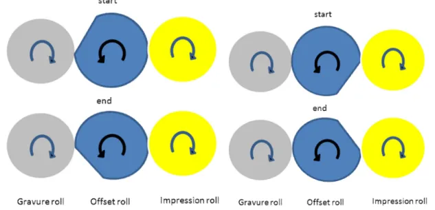
Figure 3.1.3(a) start and end states of Gravure-offset noncontact phase; (b) start and end states of Offset-impression noncontact phase
Figure 3.1.4 system response: nomenclature of the various disturbances at GR=2 Figure 3.1.5 Overall control system with fuzzy GR estimator.
Figure 3.1.6 System response for different values of GR. The cycles under consideration are indicated.(a) GR=2.00075;(b) GR=2.0015;(c) GR=2.00315; (d) GR=2.025;(e) GR=2.025;(f) GR=2.05;(g) GR=2.1.
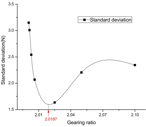
Figure 3.1.7 Standard deviation Vs GR. Minima of standard deviation is marked at GR=2.0187
Figure 3.1.8 (a) fuzzy input set; (b) Fuzzy output set; (c) Fuzzy control surface Figure 3.1.9.Fuzzy estimator-block diagram
Figure 3.1.10 Results when using fuzzy GR estimator
Figure 3.1.11 Finished mesh pattern(top) and single magnified silver pattern with scale(bottom) Figure 3.2.1(a) R2R system
Figure 3.2.1(b) Schematic representation of R2R system Figure 3.2.1(c) Conventional control architecture
Figure 3.2.2 Proposed hybrid controller
Figure 3.2.3 (a) Offset-gravure non-contact phase; (b) Offset-impression non-contact phase Figure 3.2.4 Tension in spans T3 and T4 plotted against time.
Figure 3.2.5 Block diagram of fuzzy controller Figure 3.2.6 Fuzzy sets
viii
Figure 3.2.7 Tension in spans 3 and 4 under different µ ;(a) µ=25,T3=5N, T4=10N;(b)
µ=17.5,T3=5N, T4=10N;(c) µ=10 ,T3=5N, T4=10N; (d) µ=8,T3=5N, T4=10N;(e) µ=5,T3=5N,
T4=10N;(f) µ=8,T3=5N,T4=5N.
Figure 3.2.8. Correlation coefficient vs scaling factor Figure 3.2.9 Final results of the self-tuning controller Figure 3.3.1(a) R2R system
Figure 3.3.1(b) Schematic representation of R2R system
Figure 3.3.1(c) Conventional control architecture without dancer Figure 3.3.2(a) Dancer system
Figure 3.3.2(b) Components of dancer system Figure 3.3.2(c) free body diagram of dancer link Figure 3.3.3 Test rig with standard tension of 5N Figure 3.3.4 Fuzzy controller
Figure 3.3.5 Fuzzy sets; (a) input set (top); (b) output set (bottom). Figure 3.3.6 Step response of position control
Figure 3.3.7 Closed loop tension control using dancer
Figure 3.3.8 Closed loop tension characteristics of the fuzzy dancer control system Figure 3.4.1(a) R2R system
Figure 3.4.1(b) Schematic representation of slot die coating system
Figure 3.4.2(a) Front view of slot die; (b) View of slot die lips and the tip of the die Figure 3.4.3 Photograph of PEDOT: PSS coated on PET substrate using slot die process. Figure 3.4.4 Resistance vs. tension plot.
ix Figure 3.4.5(a) Mean resistance vs. tension.
Figure 3.4.5(b) Standard deviation of resistance vs. tension. Figure 3.4.6 Surface roughness vs. tension
Figure 3.4.7 SEM images of coatings made at different tensions: (a)Tension=5N;
(b)Tension=7.5N; (c)Tension=10N; (d)Tension=12.5N;(e)Tension=15N;(f)Tension=17.5N; (g)Tension=20N; Image processing:(h) SEM image of a sample at 40000x magnification;(i) Frequency histogram of the image(j) Thresholding process, red pixels indicate peak, while black pixels indicate valley;(k) Black and white image after thresholding.
Figure 3.4.8 Peak to valley ratio vs. web tension
Figure 4.1 (a) SEM image of mesh pattern; (b) SEM image of junction of mesh pattern. Figure 4.2 (a) Mesh pattern coated with PEDOT: PSS; (b) Junction of the mesh with coating
x
Abstract
Roll-to-roll (R2R) system has been employed successfully in a variety of industries such as graphical printing, textiles, films, foils and many more converting industries. Printed electronics is a newly emerging technology that is said to revolutionize electronics industry by providing new cheaper alternatives to the conventional electronics. It is believed to be the future of disposable electronics, organic photovoltaic, organic light emitting diodes, RFID, E-paper, and many more yet unexplored potential of flexible electronics. Several of the above mentioned have been achieved on a laboratory scale, but very few have been commercialized successfully. This thesis attempts to explore the potential of R2R system to mass produce printed electronic components. The focus being on application of fuzzy logic to control the tension of the web on which printing takes place. Even with fuzzy logic several different approaches have been tried depending on the printing process. Especially worth noting is the absence of system model while designing the controllers. Rather the existing controllers are replaced with better fuzzy controllers, or are used to augment the existing controllers. Occasionally simple statistical tools have been employed to help develop the intuition that is the core of fuzzy logic. Based on the intuition and a thorough study of the printing process itself, control architectures have been developed for two printing processes, namely offset printing and slot die coating. Further a new model less approach has been used to prevent propagation of tension from one tension span to the next, which is a very commonly observed phenomenon in R2R systems. This will not just help printed electronics but will also be beneficial in disturbance prone converting industries.
1
1. Roll-to-roll system
1.1. Introduction to Roll-to-roll system
R2R system has come a long way since its initial application. R2R system is typically made up of a number of rollers that are held by bearings. The bearings in turn are fixed on the machine frame. The machine frame is ideally made of vibration dampening steel although more flimsy machine frames can be seen in literature. Material processed by the R2R system is known as web. Web may be defined as a material whose width is orders of magnitude larger than its thickness and length being orders of magnitude larger than the width- this definition holds good for paper, textile, films and foils. Although an R2R system may process materials that have width and thickness in the same order of magnitude, such as threads and ropes, in this thesis we deal with only web. The function of R2R system is to unwind material in the form of web, process it, and either cut it (as in newspaper printing), or rewind it. The processing may involve a number of things, like printing (slot die, offset, gravure, electro-hydro-dynamic printing, etc), plasma treatment, static removal, curing etc. Factors that have the most effect on the processing of web are
· Web tension, and
· Lateral and longitudinal registration.
As mentioned above, the web is transported via the R2R system by a number of rolls. These rolls fall into two categories, driven rolls and idle rolls. Besides these at unwind and rewind sections pneumatic expanding mandrels are used to hold and turn reels of the web. The driven rolls are turned by servo motors. Web tension may be denoted in two ways, as longitudinal force exerted by the web as a result of the strain in the web and as longitudinal force per unit width of the web. Both definitions are commonly used in industry as well as academia. Basically the R2R system is designed to move the web from unwind to the rewind section through the processing span, while applying a suitable tension without permanently deforming the web-unless that is part of the process. There are some rules of thumb that are commonly applied while using the R2R system for conventional applications; these have also been cited in scholarly work. But printed electronics is very distinct from the graphical printing industry. The requirements of precision of tension and registration are far greater and the processes themselves are very different from conventional printing industry. An R2R system can assume many forms depending on the
2
purpose for which it is built. The complete R2R system used in this work is shown in figure 1.1, illustrating each individual component or section of the system.
Figure 1.1 R2R system
1.2. Importance of R2R system in printed electronics
Electronics industry has over several decades, perfected techniques to fabricate electronics circuits. These circuits are typically made up of a number of layers of semiconductor materials with specific electronic properties. Fabrication of these layers is a lengthy process known as lithography. Several variants of lithography exists depending upon the precision required. Typical lithography process involves first a coating process such a sputtering upon a silicon wafer, followed by application of photoresist, followed by exposure of the photo-resist to curing beam through a mask, then the unexposed photo-resist is washed away with the aid of an appropriate solution. This is followed by etching to remove unwanted region of the coating.
3
Finally an appropriate solvent is used to remove the remainder of the photoresist. The above steps are illustrated in figure 1.2 (a).This whole process can produce only one layer. And the above description is very conservative as more intermediate steps may be involved depending on the process and material. Since a devices is usually (except may be resistor) nevermade of a single layer the total steps will be very large. The reason this lengthy process is employed is because it is effective in manufacturing reliable and precise electronic circuits ranging from microns to hundreds of nanometer size scale. Comparison of 1.2 (a) and (b) gives a good idea of the difference in the fabrication time and effort between conventional and printed electronics.
4
While it has already been established that conventional silicon based electronics cannot be replaced in the near future by printed electronics, printed electronics will play a crucial role in the fabrication of electronics where the accuracy and size of the circuits are not very important. Especially useful will be the fabrication of printed circuits that have resolution of a few microns and above, and large area printed electronics. These could be manufactured more economically by direct printing method than by conventional means.
R2R based fabrication is the next logical evolutionary path of printed electronics primarily due to its ability to mass produce. Flexible solar cellsand Organic light emitting diodes (OLED) have already been manufactured on the R2R system. Although not yet commercialized, they hold great promise. The flexible solar cell/organic photovoltaic (OPV) and OLED demand will be great in the coming decade. OPV’s have been proven to be less efficient than the conventional solar cells, but it is believed that their cost of production will be considerably reduced by the fact that they can be mass produced on R2R system. OLED is also similarly expected to be in demand and is expected to completely dominate the lighting industry. RFID antenna has been printed in R2R system. The accompanying circuit is too complex to be printed commercially; hence a combination of printed and conventional electronics is currently used in RFID tags. While some of the limitations in the R2R based commercialization of some of these products is due to absence of suitable material in the device, some can be attributed to the R2R process itself. Electronics is expected to be printed on flexible substrate, but electronic devices that thin are flimsy and may not successfully survive the R2R processing. R2R industry has its own guidelines which are not very sympathetic towards printed electronics. In this context it will be wise to develop controllers and tension and velocity control guidelines specifically for manufacturing printed electronics in R2R system. It is also crucial to develop controllers custom tailored for R2R systembased printing and coating techniques.
5
2. Web tension control system 2.1. Hardware
2.1.1. Servo pack
Servo packs are the most crucial part of any R2R system. Each servo pack has two components · A servo motor.
· A servo amplifier.
The purpose of a servo pack is to provide a torque or velocity output at the output shaft of the motor following as precisely as possible the input command given to it, which may be in the form of analog or digital signal. Originally servo packs were designed to follow position control commands. But the automation industry has developed requirements for different specifications of servo packs. The servo packs currently come in a number of configurations, but usually they all aim to control the position, velocity and torque at the output shaft of the servo motor. Nowadays the versatile servo packs are designed to simultaneous control two or more combinations of torque, velocity and speed. One of the most commonly used servo motors in CNC machine spindles, works on positions control mode and is operated by introducing pulse trains. The servo pack reads the pulse train and moves the motor through a specific angle corresponding to each pulse sensed. Another common configuration for the servo mode is the torque velocity combination. This is often used in converting industry. There are two variants of this combination:
· Velocity control with torque limit. · Torque control with velocity limit.
In the first instance the velocity is tightly controlled subject to torque limit. Thus the velocity is followed based on the command velocity by changing the torque to the motor, but if the torque ever exceeds the torque limit command the velocity tracking error is ignored. In the second instance the torque is controlled tightly subject to velocity limit. Both these modes are used in different regions of the R2R system. Every R2R system can be divided into sections called spans. Basically it is the length of web between two consecutive driven rolls occurring on the web as it travels from the roll from which it is unwound(un-wind section) to the roll on which it is rewound(re-wind section). The tension in each span has to be set according to the process being
6
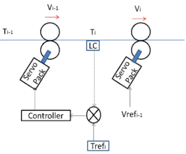
performed in the span such as un-wind, printing, re-wind etc. In any R2R system there will always be a driven roller that controls master velocity of the system. Usually it’s a nip roller. A nip roller may be defined as a driven roll that is hold the web against another roller that applies a pressure so that there is no slip between the web and the nip roller. The master velocity roller is driven by a servo motor that is usually operated in velocity mode with torque limit. Tension in the spans that follow the master velocity roller are controlled by driven rollers on the downstream end of the span, while those spans before the master velocity roller are controlled by driven rollers on the upstream end of the span. The tension controlling rollers are often set on torque control mode with velocity limit. The terminology related to spans is illustrated in figure 2.1.
Figure 2.1(a). One web span between two driven rolls. T is the tension of the web and subscript gives the span number. V is the linear velocity of web at the specified roller.
Figure 2.1 (b). Control of tension in a span after the master velocity roller. LC is the load cell. Tref is the reference tension of the given span and Vref is the reference velocity of master
7
Figure 2.1 (c). Tension control of web before the master velocity roller.
Servo motor may be defined as a motor that is capable of delivering torque while at the same time giving feed back to the servo amplifier. The torque output of the servo motor is dependent upon the current supplied to it. This is determined by the servo amplifier. Feedback from the servo motor can be in many forms. It can be current or voltage output from a tacho-generator for velocity feedback, pulses from an incremental encoder for velocity feedback or digital signal from an absolute encoder or potentiometer for position feedback. Choice of feedback will depend upon the application. But incremental encoders known as quadrature encoders have become quite popular. Pulses produced by the encoder can be converted into velocity, position by the servo amplifier. Based on the command given to the servo amplifier and the feedback it receives, the control system in the servo amplifier determines current to be delivered to the servo motor. The servo motor and servo amplifier used in this work are HC-KFS73 and MR-J2S-70A, respectively as shown in figure 2.2.
8 (a)
(b)
9
Servopacks could be avoided by replacing the servo motor with an ordinary electric motor coupled to a feedback device and the servo amplifier with a power inverter. Servo packs are preferred in industries as well as laboratories due to several advantages. Firstly the servo packs come equipped with built in safety features that prevent damaging situations to both the motor as well as the equipment, such as over current, over velocity, excess vibration to name a few. These may be implemented from scratch for a custom built system but will require low level implantation, and is as such beyond the scope of this work. Commercial servo-packs have advanced to the point where practicing engineers need little knowledge of control engineering to implement complex automation tasks. For a standard motor torque is not a linear function of current but the servo packs handle the linearization and we need only provide an analog signal to the servo pack and torque is a linear function of this signal. One of the widely used servo pack types in converting industry has simultaneous torque and velocity control mode. Wherein, the velocity is controlled subject to a torque limit and vice versa. In feedback control one of the parameters-velocity or torque- is used as the control parameter, while the other is set as a multiple of the initially set parameter. The multiplication factor is usually set as a constant by the practicing engineers based on their experience. As to which parameter among velocity and torque are to be used as control parameter and which as limiting parameter is a topic under debate by practitioners. In this work torque control with velocity limit has been used in all the servo motors in the experimental setup. Which implies that torque varies linearly with respect to input to servo pack which is -8 to +8 volts (-1200to +1200 N-m) and input velocity limit is-10 to +10 volts (-3000rpm to +3000 rpm). Mitsubishi brand servo-amp (MRJ2S70A) and servo motor (HC-KFS-73) were used.
2.1.2. Load cells
Tension in a span is measured with the help load cells. Load cells provide feedback to the tension control system. The load cell is essentially an elastic structure that deforms linearly corresponding to an external load with in prescribed load limit. Deformation in an ideal load cell should be minimal but is unavoidable as the load is measured from the deformation. Deformation
10
of the load cell is measured using a precise strain gauge. A half bridge strain gage present in the load cell is used to measure the strain. Load cell used has capacity to measure loads up to 50 lbs. This equates to approximately 250 N. The load cell is cantilever type and has a mechanical stop to prevent breakage of the device under overload. Also the relation between the strain and load is linear within the rated load. This implies that the resistance output from the strain gauges is also linearly related to load. Hence linear scaling of the resistance measured can be used to calibrate the load cell within the software. The load cell used for this work is shown in fig 2.3.
11
2.1.3. PXI system
PXI is a rugged PC-based platform for measurement and automation systems. It may be called an industrial PC. PXI follows an open industrial standard governed by the PXI Systems Alliance (PXISA). In this work the National Instruments (NI) PXI-1042Q chassis and NI PXI-8110 embedded controller have been used. Physically the PXI system is a chassis that can house a controller and a variety of cards. The controller is the PC part of the PXI system. PXI chassis can accommodate a number of cards in them depending on the model. The cards follow the PXISA standards. These cards interface with the PC. There are a variety of cards available in the market that can convert signals following a plethora of protocols and communicate with the PC, like TCP/IP, PROFIBUS, RS-232, IEEE-1394, motion control etc. Thus allowing a single system to process digital, analog, audio, video and many more types of signals and produce outputs as needed. This construction allows flexibility and at the same time the construction is rugged. PXI standard allows for real-time communication of data with PC.NI also provides a windows based software called LabVIEW. This software interfaces with the PXI cards. Programs can be written using this software that run on the PC. Programming code used in this software is known as G-code. It is a graphical programming language similar to that used in programming Programmable Logic Controllers (PLC’s). Block diagrams that perform different tasks on the acquired data are wired together in specific sequence to perform the required computation on the data and the output is again communicated via the PXI cards.
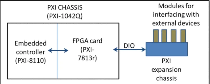
NI provides PXI cards that can communicate with external expansion chassis. These chassis can hold a number of modules. Essentially these expansion chasses digitally communicate with the modules. Modules on the other hand are versatile. Depending upon the type it can be used to produce or receive digital or analog signals. There are also special purpose modules, such as that for load cells, accelerometers etc. This greatly simplifies the task for interfacing. Each module can have different sampling rates, built in filters, signal conditioning units etc. LabVIEW has provision for communicating with each individual terminal on the module. Further there are PXI cards with FPGA chips embedded in them. These can perform some simple computations on the card itself without relaying it to the PC, such computations are usually around three orders of magnitude faster than that done on the PC, and are hence usually
12
used for processing signals from encoder. Schematic representation of data communication within the PXI system and the interface equipment is shown in figure 2.4.
Figure 2.4(a). Communication within PXI system
13
2.1.4. Rollers and spindles
There are a number of rollers and spindles on the R2R system. As explained earlier the R2R system has two types of roller the driven rollers and the idle roller. Further there are driven spindles that hold the rolls and un-wind and re-wind sections. All the different types of rolls and spindles in the given system are shown in figure 2.5.The driven rollers in the R2R system are nip rollers they actually come in pairs, and engage with each other with the web between them. These rollers have a soft surface because the rollers engage with each other and also to improve traction with the web. The material on the surface is usually synesthetic rubber. The core of the roller is made of steel and is supported by bearings. In the nip roller pair only one roller is driven by the servo pack, the other roller is rotated by the driven nip roller. The engagement between the nip rollers is usually done by applying pneumatic pressure. But in this case the assembly of the idle nip roller is heavy enough to allow a satisfactory engagement between the driven and idle nip rollers. Servo motor is not directly coupled to the driven nip roller; rather a flexible coupling is used to account for any misalignment between the roller and motor axis. The nip rollers have a suitably large diameter to allow a sufficiently large velocity of the web. In this case the nip rollers are 80 mm in diameter, which will produce a maximum velocity of 0.4 m/s. Offset printer has a diameter of 160mm which gives a maximum velocity of 0.8m/s, but the smallest diameter driven roller in the R2R system determines the limiting velocity of the system with same servo packs. The diameter of roller is crucial in the design phase because there are speed limits in a servo motor. There is usually a tradeoff involved because as we increase the diameter the velocity increases but so does the inertia of the rollers which usually leads to poor control characteristics. Idle rollers on the other hand are designed to be as small and light as possible to prevent the dynamics of their inertia from affecting the system performance. There again we have another tradeoff. Often in a multi-span R2R system the web has to take a very convoluted path, and during these sharp turns of the web path the web assumes the radius of curvature equal to that of the roller. Since the R2R system is designed to print electronic components very small radii of curvatures can be pernicious to the electronic circuits printed on the PET substrate.
14
15
Figure 2.5(b) Expanding spindles
Spindles in this thesis refer to mandrels that hold the PET substrate rolls. These spindles are driven by servo packs via coupling, and are used in the un-wind and re-wind section of the R2R system. Purpose of using these spindles is to easily fix and remove rolls from the R2R system. Mandrels have expanding grips that engage with core of the rolls. Pneumatic pressure is applied to ensure perfect fit. Often in converting and printing industries the un-winder is not driven but rather a pneumatic brake is coupled to it to maintain a tension on the web in un-wind section. This practice is not suitable because large tensions are not acceptable in printed electronics. Instead a servo motor is coupled to allow better tension control.
As mentioned earlier the Offset printer is also a driven roller, but the dynamics involved are complex and require considerable attention, hence it is dealt with in detail in a separate section devoted to offset printing.
2.2. Slot die
Slot die is one of the simplest coating methods in existence. The slot die used in the R2R system is shown in figure 2.6. It is worth noting that slot die is just a precisely machined ink dispensing unit. Essentially the slot die dispenses ink uniformly on to a very precisely machined die. A complete Slot die system is typically made up of three distinct parts. The first is the slot die body. This is a precisely machined cavity that holds the die. Also there are air venting valves to remove the excess air form the die body. The second part is the die and the third is the ink pump. Slot die is shown in figure 2.6.
16
Figure 2.6.(a)Front view of slot die;(b) Isometric view of slot die
The surface tension causes the ink to flow along the surface of the die. Web is moved at a constant rate at a constant tension underneath the slot die. Due to close proximity of the die lip to the web, the ink flows from the die on to the web, and the stripes of ink left on the web are same as the shape of the die. One important parameter that controls the quality of coating besides web tension and velocity is the gap between the die and the web. This gap is adjusted with the aid of power screws shown in figure 6. One of the reasons this process is preferred in coating over others is that it is a non-contact process wherein the thickness of the coating can be controlled very accurately and the process renders itself to mass production. Besides this process does not affect the R2R system control because the process does not affect the R2R system dynamics.
17
2.3. Offset printing
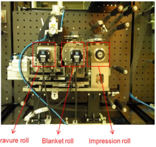
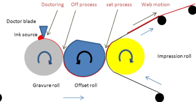
Offset printing is a process of choice when the precision of the patterns and mass production capabilities is a concern and printed electronics requires both these qualities. Offset printing is a contact printing process. Which means the printing device comes in direct contact with the web. Every offset printer has three important components-gravure roll, offset roll and impression roll. There is another similar process that is a little less complex known as the gravure printing, but the offset printing is more precise than the gravure printing. Another related process is the flexographic printing. The commonality between the three processes is that the desired pattern is first engraved onto a hard surface. The hard surface can be plane or cylindrical. Of all the three processes gravure printing is the simplest. In this method the pattern etched on the gravure surface is the mirror image of the desired pattern, because the pattern is directly applied to the substrate (material to which the pattern is to be printed). It is crucial that the substrate be softer than the gravure because pressure is applied to help transfer ink. This method is used often in graphical printing industry to print upon paper and plastic films. Also it has been applied successfully in printing electronic circuits where the precision required is not much. Flexographic involves making protrusions on the printing rolls such that the ink is only on the protrusion. This method is precise but requires very sophisticated ink transfer mechanisms.
18
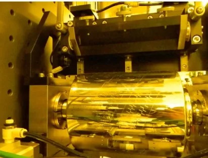
As explained earlier gravure offset printing (also known as offset printing) is one of the most precise printing techniques in existence. In this work the gravure offset printer has been used and is intended to be applied with the R2R system. The gravure offset printing can be explained as follows. The gravure roll is engraved with the pattern to be printed. Originally this process was developed for printing on uneven surfaces; hence the gravure would actually be a plain surface. This was changed to a roller for mass production of prints for graphical printing requirements. The gravure roll used here is shown in figure 2.7 . Gravure rolls are made in a number of ways. Usually a well ground copper roll with a steel core is used as the starting material. On this surface the engraving is made to resemble the desired pattern. Usually the desired pattern is not made as it is, if so then the gravure is known to have intaglio pattern. For fine printing requirements as is required in printed electronics the desired pattern is broken down into smaller sections called cells. The cells are actually pits that hold a predefined amount of ink. This approach is known as gravure printing. The reason that gravure engraving is used is to make sure that the amount of ink transferred to the substrate can be controlled to a greater degree than the intaglio printing. Also the uniformity of the final pattern can be ensured by creating cells. These gravure cells are generally created by three methods:
· Laser engraving.
· Electric discharge machining (EDM). · Diamond stylus engraving.
In laser engraving a laser creates the necessary cells by moving along the pattern area, the cells may be created in single pulse or in a series of pulses. Laser engraving does not guarantee accurate cells structure. Also removal of material from cell does not take place. EDM is a process very similar to the laser engraving but is very efficient in removing the material that is engraved out of the cells. In this process an electric arc is struck between the gravure roll surface and an electrode. A fluid is passed to cool the gravure surface as well as to remove the engraved material. This allows creation of better cells. Since the material from the cells is removed instantaneously protrusions are not formed around the cells as is usually the case with laser engraving. The third popular method of diamond stylus engraving produces the best finish of all the three processes. In this method the cells are formed of diamond tips shaped in the form of the
19
desired cell shape. The diamond stylus is impinged on to the gravure surface. This method still leaves material behind as the stylus merely displaces the material from the cells into the surrounding. Following the engraving process the gravure surface is chrome plated and finally polished to have a mirror finish.
2.4. Electro hydro-dynamic/electro spray deposition (EHD/ESD) system
EHD and ESD are processes for fine patterning and coating respectively. These techniques are currently being developed for application in printed electronic industry. But for mass production of printed electronics it is essential that these be implemented in an R2R system. It is crucial that these methods are implemented on an R2R system.
Basically EHD is the process of applying as strong potential drop between a nozzle containing ink to be patterned and the substrate. The ink in the nozzle is already maintained at a pressure. The electric field causes the ink to flow down to the substrate. The flow can be either in the form of droplets or in the form of a continuous jet depending upon the type of electric field applied-pulses or D.C. One of the key aspects of this technique is that the final pattern can be as small as 1/80 of the nozzle diameter. This allows for very fine patterns. ESD almost the same as EHD only that the distance between the substrate and the the nozzle is much larger and the jet splits into a fine spray.
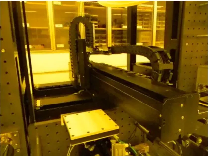
EHD process is regarded as the future of printed electronics. But they come with a tradeoff. EHD process requires that the nozzle be moved along the path of the desired pattern. This presents a bottleneck to the R2R process. While other R2R processes work at the same pace as the R2R system this method is highly dependent upon the pace of the process itself which is extremely slow. The EHD system is shown in figure 2.8. Basically the EHD system can be likened to a CNC machine with 3-axis. The machine moves the nozzle in the X, Y and Z axes. The X and Y axis allows the nozzle to make patterns on the substrate while the Z axis is meant to adjust the gap between the nozzle and substrate so that the process may occur. ESD process also presents a bottleneck in that it may require several passes before a coating of required thickness is achieved. Both these processes slow down the whole R2R system if they are required for creation of an electronics device. For EHD system it is crucial to stop the R2R system completely so that the patterning may be completed. Thus the R2R system has to stop at regular intervals for the
20
patterning and then restarted. R2R system startup and stop are usually not very smooth and is definitely time consuming. Therefore the system cannot run at high speeds.
Figure 2.8. R2R based EHD system
This thesis deals almost exclusively with web tension control under different processing techniques, although lateral and longitudinal registration also is affected by poor tension control. Fuzzy logic has been used as a means to implement the control strategies, to allow swift control system design. A model based controller has also been implemented but the model was built only for augmenting an existing fuzzy controller.
2.5. Literature survey
The literature pertaining to web handling is vast but is spread across several decades. The progress in literature is also relatively slow due to saturated nature of the field. Literature in control of R2R system is even scarcer. Significant advances in drives and electronic controls have taken place only in the last decade. But as and when new processes are introduced to the already vast list of R2R processes the new literature begins to emerge. Printed electronics is a
21
field which needs to merge with the R2R processing techniques in order to mass produce electronics at affordable prices. This has been considered for a while, but is yet to be a fully realized. Advances in embedded computing technologies like FPGA and multicore parallel processing have allowed the use of more computation intensive algorithms such as genetic algorithm(Tran et al., 2011) for control of R2R system.
2.5.1. Tension control
Web tension control has been extensively studied. Since multi-span R2R system is a time varying nonlinear system it is often studied using some nonlinear control theory. Even in nonlinear control theory the problem is often solved by linearizing it. This section of literature review is exclusively dedicated to web tension control. Since web tension control is a very old subject and a lot of literature has been published on the subject in the past few decades, this work focuses on relatively recent work, especially in the past decade. This is because; in the last decade digital industrial computers and microprocessor based drives have come into extensive use in the industry, starting a new era in R2R based industries.
Ku Chin Lin (Lin, 2003)has proposed and implemented a method wherein a single span R2R system is operated without a direct feedback from the load cell. In this method he has used an observer to predict the web tension and use it as feedback for web tension. Although written in 2003 it is obvious from the goal of the paper that tension transducers-load cells- were expensive and possibly not long lasting, this warranted for a feedback free tension control system. Also noteworthy is the fact that implementing such a system would have required a computer that predicts the tension. Dynamic equation of tension has been derived from first principle. This equation is crucial to this thesis as well. Basically it relates the tension of the current span with the tension and velocity of the previous span.
……….(2.1.1) Where,
22
V k =Velocity of the kth span as measured at the controlling roller of the span;
=Rk*ωk
Where, Rk= radius of the controlling roller of the span; ωk= angular velocity of the controlling roller.
L=length of the given span C=spring constant of the web
Another significant contribution of [Lin, 2003]is the modeling of friction and inertia of the rolls. The roll radius is calculated as a function of initial radius and angular displacement. This radius is used to compute the moment of inertia of the rolls. Although [Lin, 2003] has derived the relation between tensions of adjacent spans, it does not use it, because the work has been implemented on a single span system. This creates a problem that can be easily linearized and is as such within the scope of solution within the frequency domain. The controller is in effect a PI controller with gains being modified as the roll radii change. Further the effect of roll eccentricity has been accounted for in the design. The final controller performance has been shown to be at par with the existing closed loop feedback.
A decentralized control system by [Pagilla et al., 2007], has developed for a multi-span R2R system taking into account the system model. The system model takes into account variation of roll diameter, and inertia. The experiments have been done on a large 3-span industry scale web handling system, in which the system is divided into three single-input-single-output (SISO) control systems. Equilibrium conditions have been applied to each individual span and the drive velocities and torques are computed. Finally the results have been proven to be better than the conventional PI controller.
Tension control has been dealt with in a number of ways in the past. [Weixuan Liu and Davison, 2003] have dealt with, using principles that are applied in servo systems. In their work a 2-span R2R system has been used. Besides the control approach the paper is very informative about the performance criteria that are generally followed in web handling. Some of these criteria are that web tension be set at 10-25% web yield strength and kept within 10% of this set point during run time and 25% of this set point at speed set point change. These criteria are off course for general
23
web handling and may not hold good for all applications. A detailed study of these is done in section 3.3. [Weixuan Liu and Davison, 2003] also discusses the several potential methods to design tension controller such as SISO, MIMO and system identification along with their merits and demerits. Among these it is said that SISO is the easiest controller to design, but will lead to poor performance due to neglect of the interactions between the spans. MIMO is said to be effective but requires a very accurate system model which given the scale of the system is difficult to obtain. The controller in [Weixuan Liu and Davison, 2003] finally designed assuming that the system is linear time invariant (LTI).
[Okada and Sakamoto, 1998], [Weixuan Liu and Davison, 2003], was one of the first to apply a control method other than conventional control theories to the control of a web handling system. This work was purely simulated, but the simulation was done on a very realistic model of the system. The model featured most of the elements on a typical web handling system such as unwinder, draw roll, dancer and a rewinder. Also the web is modeled as a visco-elastic element which is hardly seen elsewhere. The most prominent part of the work was that the controller used was based on fuzzy logic. Fuzzy controller itself is simplistic (refer to section 3.1 for fuzzy logic jargon). Fuzzy input sets were triangular while the output is given by fuzzy singletons. Tuning of the controllers is done by modifying the output scaling factors. A fuzzy self-tuner changes the tuning parameter for each decentralized controller based on the performance of the system.[Sakamoto, 1999] discusses another simulation study that measures the interaction that exists between the different spans of a R2R system.
After a long gap in web tension literature another unconventional control approach was introduced by [Chen et al., 2004]. This work introduced the idea of applying Artificial Neural Nets (ANN) to R2R control for the first time. This paper features yet another realistic simulation based control system. The mathematical model has all the parameter variations that happen in the real system. The application of neural network is to account for the uncertainties and the un-modeled errors that exist in the system.
[Tran et al., 2011] and [Choi et al., 2011] have used back stepping control principle to achieve precise web tension control of a 2-span R2R system. Back-stepping may be regarded as the
24
middle path between SISO and MIMO control approaches. In [Tran et al., 2011] have used back-stepping with modified genetic algorithm to obtain the optimal control of web tension, while [Choi et al., 2011] has just used back-stepping controller. It is worth noting that in this control approach the interaction between the different spans is taken into account but it regards the span prior to the controlled span. Further the back-stepping controller is also supported by the conventional control theories as it is designed to satisfy Lyapunov stability criteria. Genetic algorithm is a very efficient optimization technique which prevents any chances of convergence to a local optimal control solution. But due to the computational complexity of the method, in [Tran et al., 2011] it is done in simulation and applied to the real system.
Registration error is the error in the alignment between two consecutive patterns printed one on top of another. [Kang et al., 2010a] and [Yoshida et al., 2008], are the only ones to discuss registration control in recent times. Registration may be regarded as a separate field in printing controls, but is closely associated with tension control and lateral control.
[Imamura et al., 1999] have applied closed loop tension control of a filament winding system using feedback from a load cell. The controllers tested in this work are PID and I-PD. This is in effect a single span system.
[Knittel et al., 2001] have implemented a PID based feedback control of anR2R system. The contribution of this work is test with a semi decentralized gain scheduled control of a multi span R2R system. Nip rolls have been avoided in this work leaving room for web slippage. Also it is stated that a gain scheduling based controller is more effective in limiting the coupling between the tension and velocity control.
Accumulators are used in R2R processing lines that are very ling and have many spans with a variety of processes being done on the web. Under these circumstances it is essential that the process is stopped as infrequently as possible. Because if the R2R system stops it is difficult to restart all the processes and optimize the process parameters. But in most R2R systems the unwind rolls and rewind rolls have to be changed-as unwind roll exhausts and rewind roll is fully wound. The accumulator is a section that is added soon after the unwind section and just before
25
the rewind section. Off course this applies only to low speed operation. Basically the accumulator is a collection of idle rollers, the distance between these idle rollers can be changed with the aid of a prime mover-usually a hydraulic cylinder that allows the idle rollers to change the web length within the accumulator. [Pagilla et al., 2001] have developed a simplified state space model of an accumulator taking into account the dynamics of tension, the accumulator set up and the pressure of the hydraulic cylinder. Further the model is tested in a real accumulator. [Pagilla et al., 2003a] has added to[Pagilla et al., 2001], the dynamics of the driven rollers in entry and exit of the accumulator. Further a closed loop stable controller has been proposed along with an observer for tension control. In [Pagilla et al., 2004] the system proposed in [Pagilla et al., 2003a] has been validated in an actual R2R system.
Dancers are yet another mechanical device used to both control as well as to measure the tension a span. Also during start and stop of the system they perform the crucial task of damping any vibration. Basically it is very similar to an accumulator because it functions by varying the span length. But the dancer system typically cannot release or withdraw as a large a length of web as an accumulator. The dancer is a prime mover driven system that can is used both in an active as well as passive sense. In its passive form, the dancer is an idle roller that is loaded with a constant force that tends to increase the span length by moving. The force for this motion comes from a dead weight, a spring or a pneumatic cylinder. When the tension in the web exceeds the force exerted by the force from the external source the dancer roll moves to reduce web span and vice versa. A transducer attached to the dancer roll can measure the motion and there by act as a tension transducer. In an active dancer system the external applied force can be changed to actually perform closed loop tension control. [Pagilla et al., 2003b], have used an active dancer system to reduce periodic tension disturbances caused by an eccentric roll. Three approaches have been followed to achieve this-PID based, internal model based and a linear quadratic (LRQ) optimal controller. The LRQ controller has been found to be better than the PID controller. R. [Dwivedula et al., 2006], have compared the performance of an active dancer, passive dancer and dancer free system. The results show that the active dancer performed better at reducing the disturbances than passive dancer followed by the dancer free system. G. Ponniah et al [PONNIAH et al.,2012] have used a new approach to controller design for dancer system. This method has been described in detail in section 4.
26
Roll eccentricity can cause fluctuations in tension. This is primarily due to variation of the linear velocity due to eccentricity although the servos can tightly control the angular velocity. Since the velocity and tension are strongly coupled, the tension tends to vary as a result of the eccentricity of rolls. [Shin et al., 2002] have measured the linear and the angular velocity of a roll with unknown eccentricity and have modeled the eccentricity. Finally the known eccentricity has been used to modify the angular velocity of the drive so that the linear velocity is constant.
Web tension is regarded as a very important parameter in determining the quality of products processed on the R2R system. [Lee et al., 2010a] have managed to control the thickness and roughness of patterns made by a gravure printer on a flexible substrate using an R2R system. It is proven that the surface tension of liquid on a substrate changes as tension is applied to it. This has an effect on the pattern as it controls how the ink spreads on the surface of the substrate. [CHOI et al., 2012] have done a similar study on the slot die coating process. The ink used was PEDOT:PSS on PET substrate.
2.5.2. Printing
[Mäntysalo and Mansikkamäki, 2009] designed and manufactured a transmission line and a patch antenna for 2.4 GHz ISM band. One test set was manufactured using conventional etching technique for a reference with a metal thickness of 17 µm. Two other test cases were fabricated using an inkjet-based printing technique that is described in more detail later in this paper. Printed patterns have thicknesses of 2.5 and 0.5 µm. This work evaluates the suitability of printed electronics in high-frequency applications. Insertion loss in the 60 mm-length transmission line was 0.1 dB higher in the case of the printed (thick) line than in that of the etched line. Furthermore, impedance matching bandwidth was almost the same in all antennas, although a small decrease in radiation properties was found.
A gravure offset printing system by [Lee et al., 2010a] composed of a roll-to-roll web-providing apparatus, a cup-type encapsulated doctoring blade, a flat gravure plate, and CCDs for line-width measurement has been devised for printing the electrodes of flat panel display (FPD) devices. This system may be characterized as a small experimental system capable of carrying out
27
printing tests prior to using a huge gravure offset printing system for mass production. The conceptual design of this gravure offset printing system is focused on conducting the reliability accelerating test and on mimicking the huge mass-production printing process required for FPD parts such as plasma display panel electrodes.
The thesis by [Kulachenko, 2006] addresses two topics in mechanics of paper webs in printing press applications. First is the dynamic behavior of the travelling webs. Second is so called “fluting” after heat-set web-fed offset printing. A non-linear finite element formulation has been developed in this study for simulation of travelling webs. The results of the studies shows that for the tension magnitudes used in the printing industry the critical web speed lies far above those used today. Speed limitations are rather caused by ink setting and tension control problems. Fluting was explained as a post-buckling phenomenon due to small scale moisture variations developing during through-air drying.
A gravure offset printing process has been developed by [Pudas et al., 2004a] for Ag-filled polymer conductor ink. Pad printing and roller type printing have been used. Curing and electrical properties have been studied. A roller type of gravure offset printing has been used to evaluate the printing process and pad printing to print on the non-planar substrates. Based on differential scanning calorimetry (DSC) and resistivity measurements during ink curing, it was found that the ink had an optimum curing temperature of 140 ◦C. Square resistance of 300 and 150µm wide lines can be as low as 20 and 28mΩ/sq., respectively, for 7–8.5µm thick line. The minimum line width was 70µm. This minimum line width can be reduced with different ink solvents, but in this case the line thickness suffers and the square resistance increases, respectively.
The development of gravure-offset-printing and low temperature cofired ceramic (LTCC) technologies for the miniaturization of electronic devices and components is described in thesis by [Lahti, 2008]. The development work has been verified by several applications. Several aspects of gravure-offset-printing have to be optimised in order to make it suitable for fine-line printing and these have been addressed in the study with a focus on the printing inks and plates. Gravure-offset-printing inks were developed from commercial thick-film pastes. The effects of
28
different ink characteristics on some properties of conductor lines, such as line width and resistivity, were studied. The dependence of the conductor lines on the quality of the engravings in the printing plates was also studied. The narrowest line widths obtained were about 30 μm with an accuracy of ±5 μm.
The gravure offset printing method was examined for the manufacture of thick-film conductors on alumina, using Ag based inks. In this research by [Pudas et al., 2004b], a roller type gravure offset manufacturing process was developed to give conductor lines and spaces down to 20 µm, together with a low square resistance. Novel hydrocarbon resin based inks have been used and compared to traditional ethyl cellulose based inks normally used in thick-film technology. The inks had a high viscosity compared to graphical inks due to their high solid content, which was necessary to enable a high printed mass. Different printing parameters were studied and printed sample properties were statistically compared. The results show that the cross sectional area of the lines is the best correlating measured property to describe the quality of the printing. 100% of the ink was transferred from the blanket to the substrate after 30 seconds. Prints from ink containing 85 wt.% of silver with optimized parameters resulted in a square resistance of 5 mΩ/sq. for 300 mm wide and 17 µm thick lines produced from a single print. These promising results are important requirements for high throughput electronics manufacture.
The reliability of gravure offset printing and presents a mechanism on how the width of the printed line increases on repeated printings is discussed by [Lee et al., 2010b]. Of the various printing process parameters, such as the resting times between doctoring, off, and set, printing velocity, printing pressure, and so forth, we investigated the effects of printing velocity, printing pressure, and blanket’s thickness on the reliability of gravure offset printing. As the printing velocity increases, the reliability of gravure offset printing also increases. This is because the actual contact time between ink and blanket decreases, resulting in less solvent absorption into the blanket. Printing pressure does not have much influence on reliability. Even though some change was observed, it was within the range of experimental error. Under sufficient printing pressure, this observation implies that the more important factor as regards the absorption model is time rather than pressure. As the thickness of the blanket increases, the reliability also
29
increases. In the case of a thin blanket, in particular, the reliability of gravure offset printing is sensitive to changes in thickness.
The inks used in gravure–offset printing are non-Newtonian fluids with higher viscosities and lower surface tensions than Newtonian fluids. This paper by [Ghadiri et al., 2011] examines the transfer of a non-Newtonian ink between a flat plate and a groove when the plate is moved upward with a constant velocity while the groove is held fixed. Numerical simulations were carried out with the Carreau model to explore the behavior of this non-Newtonian ink in gravure–offset printing. The volume of fluid (VOF) method was implemented to capture the interface during the ink transfer process. The effects of varying the contact angle of the ink on the flat plate and groove walls and geometrical parameters such as the groove angle and the groove depth on the breakup time of the liquid filament that forms between the plate and the groove and the ink transfer ratio were determined. Our results indicate that increasing the groove contact angle and decreasing the flat plate contact angle enhance the ink transfer ratio and the breakup time. However, increasing the groove depth and the groove angle decreases the transfer ratio and the breakup time. By optimizing these parameters, it is possible to achieve an ink transfer from the groove to the flat plate of approximately 92%. Moreover, the initial width and the vertical velocity of the neck of the ink filament have significant influences on the ink transfer ratio and the breakup time.
Polymer solar cells are reviewed by [Krebs, 2009a] in the context of the processing techniques leading to complete devices. A distinction is made between the film-forming techniques that are used currently such as spin coating, doctor blading and casting and the, from a processing point of view, more desirable film- forming techniques such as slot-die coating, gravure coating, knife-over-edge coating, off-set coating, spray coating and printing techniques such as ink jet printing, pad printing and screen printing. The former are used almost exclusively and are not suited for high-volume production whereas the latter are highly suited, but little explored in the context of polymer solar cells. A further distinction is made between printing and coating when a film is formed. The entire process leading to polymer solar cells is broken down into the individual steps and the available techniques and materials for each step are described with focus on the particular advantages and disadvantages associated with each case.
30
Since D flip-flop is one of the indispensable building blocks in integrated circuit (IC) design, providing a successful way to print D flip-flop on plastic foils will be the first step to reach fully printed flexible IC. Here, the network structure of single-walled carbon nanotubes (SWNTs) as an active layer has been employed to print the driver and load thin-film transistors (TFTs) of the D flip-flop by [Noh et al., 2011b]. The same physical dimensions of driver and load TFTs were first developed to fully gravure print the D flip-flop because of the advantage of tunable electrical properties of network density of SWNTs. Therefore, the circuit design and printing becomes simpler and more convenient than using general design rules. Furthermore, the SWNT network structure in the active layer can also minimize the fluctuation of threshold voltages (Vth) of SWNT-TFTs because of the use of the same physical dimensions in TFTs. The resulting gravure-printed D flip-flop shows a clock-to-output delay of 23 ms for 20-Hz clock signal. This is the first reported D flip-flop performance using all gravure-printing method yet achieved. All-printed half adders will be the first step to the way of printing an arithmetic logic unit which will be further expanded to printing microprocessors directly onto flexible plastic foils by [Noh et al., 2011a]. In this letter, the half-adder circuit has been constructed using an all gravure printing process on poly (ethylene terephtalate) foils. To successfully operate the printed half adder, we first simulate the half adder using the parameters extracted from gravure-printed single-walled carbon nanotube (SWNT)-based thin-film transistors (TFTs) to provide a tolerable range of fluctuations of electrical parameters of the gravure-printed SWNT-based TFTs. Based on the close comparison between simulation results and attained electrical parameters of printed TFTs, controlling waviness of printed drain–source electrodes has been found to be a key factor for successfully executing the function of a printed half adder on the plastic foils.
A roto-gravure printing technique has been developed for conductive lines on paper and plastic films by [Pudas et al., 2005]. Rotary-screen-printing was used to make comparative prints. The inks contained metal particles in an organic medium and were cured in temperatures of 70–120 ◦C, limited by the substrate durability. The following conductor line properties were characterized for different substrates: resistance, yield as a function of line width, coil inductance, folding endurance, adhesion, printed antenna properties and maximum current density. A printed