A solar photovoltaic system with ideal efficiency
close to the theoretical limit
Yuan Zhao,1,2 Ming-Yu Sheng,1,3 Wei-Xi Zhou,1 Yan Shen,1 Er-Tao Hu,1 Jian-Bo Chen,1 Min Xu,1 Yu-Xiang Zheng,1 Young-Pak Lee,4 David W. Lynch,5 and Liang-Yao Chen1,*
1Department of Optical science & Engineering, Fudan University, Shanghai, 200433 China 2Department of Optics and Electricity, Shanghai Second Polytechnic University Shanghai, 201209 China
3Department of Electronic Information, Shanghai Business School, Shanghai, 200235 China 4Department of Physics, Hanyang University, Seoul, South Korea
5Department of Physics, Iowa State University, Ames, Iowa, 50011, USA
Abstract: In order to overcome some physical limits, a solar system
consisting of five single-junction photocells with four optical filters is studied. The four filters divide the solar spectrum into five spectral regions. Each single-junction photocell with the highest photovoltaic efficiency in a narrower spectral region is chosen to optimally fit into the bandwidth of that spectral region. Under the condition of solar radiation ranging from 2.4 SUN to 3.8 SUN (AM1.5G), the measured peak efficiency under 2.8 SUN radiation reaches about 35.6%, corresponding to an ideal efficiency of about 42.7%, achieved for the photocell system with a perfect diode structure. Based on the detailed-balance model, the calculated theoretical efficiency limit for the system consisting of 5 single-junction photocells can be about 52.9% under 2.8 SUN (AM1.5G) radiation, implying that the ratio of the highest photovoltaic conversion efficiency for the ideal photodiode structure to the theoretical efficiency limit can reach about 80.7%. The results of this work will provide a way to further enhance the photovoltaic conversion efficiency for solar cell systems in future applications.
©2011 Optical Society of America
OCIS codes: (040.5350) Photovoltaic; (230.5170) Photodiodes.
References and links
1. R. R. King, D. C. Law, K. M. Edmondson, C. M. Fetzer, G. S. Kinsey, H. Yoon, R. A. Sherif, and N. H. Karam, “40% efficient metamorphic GaInP/GaInAs/Ge multijunction solar cells,” Appl. Phys. Lett. 90(18), 183516 (2007).
2. J. F. Geisz, D. J. Friedman, J. S. Ward, A. Duda, W. J. Olavarria, T. E. Moriarty, J. T. Kiehl, M. J. Romero, A. G. Norman, and K. M. Jones, “40.8% efficient inverted triple-junction solar cell with two
independentlymetamorphic junctions,” Appl. Phys. Lett. 93(12), 123505 (2008).
3. W. Guter, J. Schöne, S. P. Philipps, M. Steiner, G. Siefer, A. Wekkeli, E. Welser, E. Oliva, A. W. Bett, and F. Dimroth, “Current-matched triple-junction solar cell reaching 41.1% conversion efficiency under concentrated sunlight,” Appl. Phys. Lett. 94(22), 223504 (2009).
4. S. Kurtz and J. Geisz, “Multijunction solar cells for conversion of concentrated sunlight to electricity,” Opt. Express 18(S1), A73–A78 (2010).
5. W. Shockley and H. J. Queisser, “Detailed balance limit of efficiency of p-n junction solar cells,” J. Appl. Phys.
32(3), 510–519 (1961).
6. A. D. Vos, “Detailed balance limit of the efficiency of tandem solar cells,” J. Phys. D. Appl. Phys. 13(5), 839– 846 (1980).
7. C. H. Henry, “Limiting efficiencies of ideal single and multiple energy gap terrestrial solar cells,” J. Appl. Phys.
51(8), 4494–4500 (1980).
8. G. L. Araújo and A. Marti, “Absolute limiting efficiencies for photovoltaic energy conversion,” Sol. Energy Mater. Sol. Cells 33(2), 213–240 (1994).
9. A. Martí and G. L. Araujo, “Limiting efficiencies for photovoltaic energy conversion in multigap systems,” Sol. Energy Mater. Sol. Cells 43(2), 203–222 (1996).
10. A. S. Brown and M. A. Green, “Limiting efficiency for current-constrained two-terminal tandem cell stacks,” Prog. Photovolt. Res. Appl. 10(5), 299–307 (2002).
11. A. Luque and A. Marti, “Increasing the efficiency of ideal solar cells by photon induced transitions at intermediate levels,” Phys. Rev. Lett. 78(26), 5014–5017 (1997).
12. I. Tobías and A. Luque, “Ideal efficiency of monolithic, series-connected multijunction solar cells,” Prog. Photovolt. Res. Appl. 10, 323–329 (2002).
13. S. Kurtz, D. Myers, W. E. McMahon, J. Geisz, and M. Steiner, “A comparison of theoretical efficiencies of multi-junction concentrator solar cells,” Prog. Photovolt. Res. Appl. 16(6), 537–546 (2008).
14. E. D. Jackson, “Areas for improvement of the semiconductor solar energy converter,” in Transactions of the Conference on the Use of Solar Energy (University of Arizona Press, 1955), p. 122.
15. R. L. Moon, L. W. James, H. A. Vander Plas, T. O. Yep, G. A. Antypas, and Y. Chai, “Multigap solar cell requirements and the performance of AlGaAs and Si cells in concentrated sunlight,” in 13th Photovoltaic Specialists Conference (IEEE, 1978), pp. 859–867.
16. A. Barnett, D. Kirkpatrick, C. Honsberg, D. Moore, M. Wanlass, K. Emery, R. Schwartz, D. Carlson, S. Bowden, D. Aiken, A. Gray, S. Kurtz, L. Kazmerski, M. Steiner, J. Gray, T. Davenport, R. Buelow, L. Takacs, N. Shatz, J. Bortz, O. Jani, K. Goossen, F. Kiamilev, A. Doolittle, I. Ferguson, B. Unger, G. Schmidt, E. Christensen, and D. Salzman, “Very high efficiency solar cell modules,” Prog. Photovolt. Res. Appl. 17(1), 75– 83 (2009).
17. M. A. Green and A. Ho-Baillie, “Forty three percent composite split-spectrum concentrator solar cell efficiency,” Prog. Photovolt. Res. Appl. 18(1), 42–47 (2010).
18. R. R. Willey, “Achieving narrow bandpass filters which meet the requirements for DWDM,” Thin Solid Films
398–399, 1–9 (2001).
19. R. Ramaswami and K. N. Sivarajan, Optical Networks: A Practical Perspective (Morgan Kaufmann, 1999). 20. L. Y. Chen and D. W. Lynch, “Scanning ellipsometer by rotating polarizer and analyzer,” Appl. Opt. 26(24),
5221–5228 (1987).
21. D. S. H. Chan and J. C. H. Phang, “Analytical methods for the extraction of solar-cell single- and double-diode model parameters from I-V characteristics,” IEEE Trans. Electron. Devices 34(2), 286–293 (1987).
1. Introduction
Great effort has been made recently to improve the photovoltaic efficiency of solar cells [1– 4]. The intrinsic characteristics of a single device will limit its photovoltaic response in attempts to achieve high efficiency of photovoltaic conversion in the broad solar-spectrum range [5–13]. The key to overcoming such a physical limitation is to develop a system consisting of a set of solar cells in which the photovoltaic conversion of each cell matches the sub-spectrum of the solar radiation with high conversion efficiency in its sub-region. At present, the most promising approach is to increase the number of P-N junctions by selecting suitable materials [1–3]. In practical device processing to fabricate an integrated tandem multi-junction structure, however, the number of junctions often has been restricted to be less than or equal to three [1–3] due to the critical barrier of lattice mismatch of the materials composed of IV- and III-V-group semiconductors with different lattice constants and energy band structures. For a typical semiconductor with an energy band gap Eg, there will be either
no photon absorption when the photon energy E < Eg., or high energy loss due to the
generation of electron-hole pairs when E > Eg [7]. Therefore, effective photovoltaic
conversion with higher efficiency can occur only in a very narrow photon energy region close to Eg, implying that there is significant room to develop a method in which the number of P-N
junctions with different energy gaps Eg can be larger than three by using the proper device
configuration and technique to achieve the highest photovoltaic conversion efficiency over the entire solar spectrum range. Henry, in his theoretical work, predicted that maximum efficiencies of 37, 50, 56, and 72% can be achieved for cells with 1, 2, 3 and 36 energy gaps, respectively, under the condition of a concentration of 1000 suns [7]. Luque and Marti carried out a calculation predicting that a maximum efficiency of about 63.1% can be achieved, assuming an ideal solar cell with an intermediate-energy band within the principal band gap structure [11], although difficulties, such as the complexity of the device structure and fabrication process and a very high heat dissipation density of the light concentrated on the single integrated cell, will reduce the efficiency in real applications with problems to be solved in the future.
Another useful approach was proposed to use passive optical devices without energy loss to split the solar spectrum into multiple sub-spectrum regions, each matching the energy band structure of the material with higher photovoltaic conversion efficiency in the sub-region [14, 15]. Very high conversion efficiency has been reported recently by using a configuration in which single and multiple junctions of solar cells were used, separated by a dichroic prism which reflects light above 1.4 eV and passes light below 1.4 eV with the element arrangement
of (GaInP/GaAs tandem cell)/ (dichroic prism)/ (Si single junction cell)/(GaInAsP/GaInAs tandem cell) [16,17].
In the present work we study a method in which the main solar radiation in the 300-1800 nm wavelength range is split into 5 sub-spectral regions by using 4 passive dielectric band-pass film filters, matching them optimally to the photovoltaic response of 5 individual photocells with only one P-N junction working in each region. Results with detailed data reduction and analysis show that the method demonstrated in this work, assembling a set of photocells, each with higher photovoltaic response matching a sub-spectrum of the solar spectrum, can achieve higher efficiency. Advanced wavelength-division-multiplexing (WDM) bandpass-filter technology [18,19], which was well developed in the optical communication field in the last decade, can be effectively transferred and applied to the solar energy field. The method reported here provides a way with significant advantage and indicates that more proper materials with suitable band structures can be selected to achieve high photovoltaic conversion efficiency in a narrow solar spectrum region which can be finely tuned by using conventional dielectric band-pass filters with sharp spectral edges to completely avoid optical interference and lattice mismatch effects presented in the usual tandem solar cell. The optical and electric properties of each individual cell containing only one P-N junction to play the role of photovoltaic conversion can be greatly improved. The device structure design and fabrication process can be optimized to enhance the power output by minimizing the internal resistance and other side effects, as well as to reduce the heat dissipation density by dispersing the highly concentrated solar radiation into a set of spectrally-isolated cells.
2. Theoretical models
There are mainly two kinds of theoretical models to predict the efficiency limits of a set of solar cells with different energy gaps assembled in sequence. One is the thermodynamic model, which deals with the intrinsic photovoltaic conversion process of the cell. The other is called the balance model, which is more widely used to refine the conversion process with some assumptions related to the properties of the solar cell [5–13]. The detailed balance model seems to be more suitable to study and determine the efficiency limit of a cell system in which N single-junction solar cells working at room temperature (Tc = 27°C) are spectrally
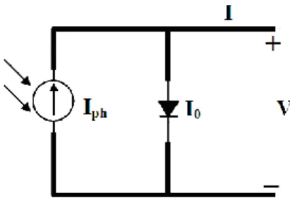
isolated from each other by using spectrum-splitting technology. The equivalent circuit diagram of an ideal single-junction solar cell is shown in Fig. 1. The I-V characteristic of the ith ideal solar cell can be expressed as [5,6]
i 0 ( ) [exp( ) 1], i i i i ph C qV I V I I kT (1)
where Ii and Vi are the external current and voltage of the ith solar cell, respectively, q is electron charge and k is Boltzmann’s constant. Ii
ph and Ii0 are the photon-generated current
and the reverse-saturated current for the ith solar cell, respectively.
Fig. 1. Equivalent circuit diagram of an ideal single-junction solar cell.
The electron current of the solar cell is generated by absorbing the photons entering the cell. Photons with energy equal to or greater than the band gap Eg are absorbed. Disregarding
photon-generated carriers are collected to produce the power output. The reverse-saturated current arises from the radiative recombination of electron-hole pairs. Assuming that the solar cell is a perfect blackbody in absorbing the radiation and each photon produces only one electron-hole pair in the recombination processes, Iiph and I
i
0 can be given by [6]
i i
ph ( ph 0), 0 0,
I q F F I qF (2)
where Fph and F0 are the number of photons absorbed and radiated per second and can be
written as 1 0 E / 0 ( ) , 2 ( ) , n n g i i ph ph h F A
N d F A
N d (3)where A is the effective area of the solar cell, Eg is the bandgap for solar cell, Niph (λ) and
N0
i(ν) are the absorbed and radiated photon numbers per unit area and per second at
wavelengths between λn and λn + 1 corresponding to the nth sub-spectral window, respectively,
and can be written as
2 0 2 2 ( ) , ( , ) , exp( / ) 1 i e i ph C C C E N N T hc c h kT (4)
where Ce is the energy concentration ratio for the incident solar energy E under 1 sun
radiation, c is the velocity of light, ν is the photon frequency and h is Planck’s constant. In terms of the I-V characteristic of the ith ideal solar cell, therefore, Eq. (1) can be written as
1 2 2 / 4 ( ) exp( ) . exp( ) 1 n n g i i i e E h C C C E qA qV I V qA d d hc c kT h kT
(5)The output power Pi of the ith ideal solar cell is .
i i i
P I V (6)
The voltage Vim and current Iim at the maximum power output condition can be obtained
from the condition
0. i i P V (7)
The voltage Vim at maximum power output obeys the following equation:
1 2 3 3 2 / 3 1 [1 ]exp( ) 1 4 [ 2y 2 ] n n g C i i e m m y y y C C C y mE kT m C E d qV qV h c kT kT k T y e e e m
(8)and the maximum power output i i i
m m m P I V can be expressed as 1 3 3 i 2 m 2 3 3 y / 1 4 1 P n exp( ) [ 2y 2 ] . g C n i i e C i m y y y m m mE kT m C C E qAk T qV qAV d V y e e e hc c h kT m
(9) The derivation of Eqs. (8) and (9) is in Appendix A.Thus, the efficiency limit of photovoltaic conversion for assembled solar-cell system can be described as 1 model 100%, N i m i in P P (10)
where Pin is the total solar radiation power incident on the solar cell surfaces and can be given
as
0
in e
P A
C Ed (11)3. Experiment and results
In the experiment, a system containing 5 single-junction cells, two lenses and four filters was configured as shown in Fig. 2. The light beam, simulating a solar spectrum, is transmitted through the first lens and focused onto the first photocell. The filter, which has a spectral window to transmit and reflect light in the short and long wavelength range, respectively, is placed at an angle of 45° in the front of the first photocell. The light which is reflected by the first filter goes to the second set of filters and photocells in sequence. After two reflections by the filters in the optical path, the second lens is used to focus the divergent light onto the
Fig. 2. Schematic diagram of the optical path with five photocells and four filters used in the spectrum-splitting solar photovoltaic conversion system.
Fig. 3. To match the spectral response of each photocell, four optical film filters have spectral transmission windows of 300-480nm, 400-630 nm, 600-730 nm and 700-870 nm, respectively, as measured by spectroscopic ellipsometry, and are used to divide the solar spectrum into five sub-spectral regions of (I) 300-480 nm, (II) 480-630 nm, (III) 630-730 nm, (IV) 730-870 nm, and (V) 870-1800 nm, respectively.
remaining sets of filters and solar cells. As shown in Fig. 3, the four filters have spectral transmission windows of 300-480 nm, 400-630 nm, 600-730 nm and 700-870 nm, respectively, as measured by spectroscopic ellipsometry [20], and are used to divide the solar spectrum into five sub-spectral regions. There is some degree of spectral overlap between two filters in sequence, resulting in five sub-spectral windows produced by the four filters: (I) 300-480 nm, (II) 480-630 nm, (III) 630-730 nm, (IV) 730-870 nm, and (V) 870-1800 nm, respectively. As shown in Fig. 2, therefore, five photocells with high photovoltaic conversion efficiency peaked at about 470 nm (GaAsP, Hamamatsu G5645), 600 nm(GaAsP, Hamamatsu G1117), 700 nm (GaAsP, Hamamatsu G1737), 850 nm (GaAs, made by the 13th institute of electronics department of China) and 1500 nm (InGaAs, Hamamatsu G8370), respectively, are used to fit optimally in sequence into the I-V sub-spectral regions.
In this study, we use a spectrally-calibrated 1000-W Xe arc lamp as the source in the solar simulator. The spectral mismatch of the solar simulator is less than 10% compared to the standard AM1.5G solar spectrum. The instability of the solar simulator is less than 1% as measured by a standard Oriel silicon cell, satisfying the condition of the standard AM1.5G solar spectrum. The I-V curve for each photocell was measured by Keithley-2400 Source Meter at temperature of 27°C [21] with the results and parameters shown in Fig. 4 and Table 1, respectively.
Fig. 4. The I-V curves of five single-junction photocells are measured under the 2.8SUN solar irradiation intensity condition.
Table 1. Parameters extracted from the I-V curves of 5 five single-junction photocells measured under the 2.8SUN solar irradiation intensity condition
Cell Material Sub- spectral region (nm) Effective area size (mm2) Short-circuit current density Jsc (mA/cm2) Open- circuit voltage Voc (V) Fill Factor (%) Measured efficiency (%) G5645 GaAsP 300-480 0.58 13.29 1.39 54.4 3.6 G1117 GaAsP 480-630 29.3 27.54 1.37 74.6 10.1 G1737 GaAsP 630-730 29.3 33.04 1.20 62.0 8.8 GaAs GaAs 730-870 3.24 36.42 0.89 59.3 6.9 G8370 InGaAs 870-1800 7.0 65.71 0.40 65.8 6.2
In the experiment, the radiation intensity of the solar simulator is varied in the range from 2.4 SUN to 3.8 SUN (AM1.5G). Then the total efficiency ηexp of photovoltaic conversion for
five solar cells can be measured and analyzed in terms of the I-V curve measured for each cell as
5 1 exp 100%, i i m m i in I V P (12)
where Iim and Vim are the output current and voltage of the single solar cell measured under
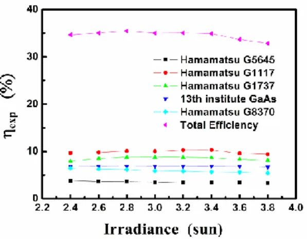
conditions of maximum output power, respectively. When the radiation intensity reaches 2.8 SUN, the highest photovoltaic conversion efficiency of about 35.6% is obtained from the results shown in Fig. 5.
Fig. 5. The measured photovoltaic conversion efficiency changes with the solar irradiation intensity.
In practical applications in which the photocell is irradiated by light from the solar simulator, a certain part of the energy will be lost and converted into thermal power Psh and Ps
in the internal shunt resistance Rsh and series resistance Rs, respectively, as shown in Fig. 6.
Because of the power Pdio consumed by the photodiode in the photovoltaic conversion
process, the final output power under load, Pout, will be smaller than the ideal output power for
which Psh = Ps =0.
Fig. 6. Schematic diagram to show that the output power will be reduced by the internal shunt and series resistances as the powers Psh and Ps, respectively in the practical application of a
solar cell.
Therefore, the output power of the ith single-junction solar cell can be described as
( ).
i i i i i out in dio s sh
P P P P P (13)
For an ideal solar cell as shown in Fig. 1, the power consumed by the internal shunt and series resistances should be zero, i.e. the internal shunt and series resistances should reach toward infinity and zero, respectively, in the solar-cell design and manufacturing process to reach the maximal output power of the solar cell with the highest photovoltaic conversion efficiency in application. The output power Piideal of the ideal single-junction solar cell can be
,
i i i i ideal out s sh
P P P P (14)
where the Pout, Ps and Psh are
2 2
, ( ) , ( ) / .
i i i i i i i i i i i
out s s sh s sh
P I V P I R P V I R R (15)
The lumped series and shunt resistance Rs and Rsh, and the reverse-saturated current for
the solar cell I0 obey the following equations, given in Appendix B: 0 0 0 0 0 1 1 exp( ) exp( ) , exp( ) exp( ) sc s sh sh T T oc T s s T sc oc sc s T T I I R R R V V V V R R I V I I V I R V V (16)
where Rish0 = -(dV/dI)V = 0, Ris0 = -(dV/dI)I = 0 are the shunt and series resistances for the ith
solar cell at short- and open-circuit conditions, respectively, and Ris and R i
sh are the internal
series and shunt resistances of the ith solar cell and can be analyzed in terms of the measured I-V curve [21], and by using Eq. (16), as detailed in Appendix B. For an ideal solar cell, the lumped series and shunt resistance Rs and Rsh will be required to equal 0 and respectively.
Assuming all five single-junction solar cells in the photovoltaic conversion system have the ideal device structure in which Ris = 0 and Rish = , the ideal efficiency ηideal of the
five-cell system can be described as
5 1 , 100% i ideal i ideal in P P (17)
where Piideal can be analyzed by using Eqs. (14)-(16) under optimal conditions. We find that
for solar radiation power in the range of 2.4-3.8 SUN, the spectrally-divided photovoltaic conversion system designed in this work can have a peak conversion efficiency of about 42.7% for a radiation intensity of 2.8 SUN, with the results shown in Fig. 7 and Table 2.
Fig. 7. Photovoltaic conversion efficiency of the spectrally divided system designed in this work to have an optimal efficiency of 42.7% obtained under ideal condition in which Ri
s = 0
and Rish = .
In terms of the detailed-balance model [5–13], the theoretical efficiency limit of the solar cell under 2.8 SUN (solar simulator spectrum) for the spectrally divided solar cell system
given in this work is calculated to reach to about 52.9%, implying that the ratio of the highest photovoltaic conversion efficiency (42.7%) for the solar system with the ideal photodiode structure to the theoretical efficiency limit can reach about 80.7%.
There is room to improve the method and to enhance the photovoltaic conversion efficiency as follows:
(1) There is an optical loss which will reduce the intensity of light incident onto the photocell due to a few percent of transmission loss by the film filters as seen in Fig. 3 and Table 1 and the multiple reflections at the internal and external interfaces of the photocells. This part of the optical loss can be minimized by improving the filter and diode designs and the manufacturing process of the system.
(2) The photovoltaic loss due to the recombination of electron-hole carriers will occur in the photovoltaic conversion process of the solar cell, decreasing the photo-excited photovoltaic current due to defects in the device material and structure. The defects can result in the recombination of electron-hole carriers before conversion into photovoltaic current, reducing the conversion efficiency. This part of the loss can be reduced or overcome by improving the device processing technique.
(3) A certain fraction of the power will be lost and consumed on the internal series and shunt resistances, as seen in Fig. 6. Due to the intrinsic restriction of the photodiode structure, the way to reduce the internal resistance effect in a complicated multi-junction-cell structure is limited. The internal resistance, which will convert a part of solar energy into the heat, can be significantly reduced by improving the device design with suitable processing technique, since there is only one single-junction diode used in the isolated sub-spectral region of the solar radiation spectrum.
(4) The highest photovoltaic conversion efficiency (60%) usually occurs only in a narrow region near the direct-energy-band gap of the semiconducting material. For most of the multi-junction solar cell structures, it is still quite difficult to achieve a perfect match between the sub-spectral region of the solar spectrum and optical response region of the solar cell due to the physical limits of the intrinsic optical properties of the semiconductor material and the device structure. By using the method given in this work, however, a proper individual solar cell with higher quantum efficiency can be optimally designed with an optical filter to fit the appropriate sub-spectral region of the solar spectrum, resulting in an overall enhancement of the photovoltaic conversion efficiency. With a multi-junction (>5) solar-cell system with each cell’s response matching perfectly its sub-spectral region of the solar spectrum this higher efficiency can be achieved.
Table 2. Measured photovoltaic conversion efficiencies of five photocells in the sub-spectral regions with comparisons to the ideal efficiency under the perfect photo diode
structure condition and the efficiency limit calculated by the detailed balance model
Cell Material Sub-spectral region (nm) Solar energy distri-bution (%) Measured efficiency (ηexp, %) Ideal Efficiency (ηideal, %) Trans-mission of filter (%) Ideal efficiency counting filter loss (η*ideal,%) Efficiency based on detailed balance model (ηmodel,%) G5645 GaAsP 300-480 18.9 3.6 5.7 84.3 6.8 10.7 G1117 GaAsP 480-630 18.5 10.1 11.2 98.3 11.4 11.6 G1737 GaAsP 630-730 16.4 8.8 10.3 94.1 10.9 11.0 GaAs GaAs 730-870 12.3 6.9 7.9 95.2 8.3 8.3 G8370 InGaAs 870-1800 28.1 6.2 7.7 7.7 11.3 5 cells 35.6 42.7 45.1 52.9
(5) In a highly concentrating solar system, the heat dissipation density of a tandem cell with its multi-junction diode structure will be very high to limit the photovoltaic conversion efficiency in practical applications. By using the spectrum-splitting method with multiple single-junction diodes used in the solar system, the total heat dissipation can be uniformly distributed in each individual photocell to reduce significantly the heat density loaded on the device. This will help to reduce the cost of the solar system under ultra-high light-concentration condition and will improve the performance of the system.
4. Conclusion
In this work, we designed and constructed a solar photovoltaic conversion system consisting of 5 single-junction photocells. Four optical filters were used to divide the solar spectrum into five sub-spectral regions. The single-junction photocell with the highest photovoltaic conversion efficiency in each suitable narrower spectral region was chosen to fit optimally into the bandwidth of each sub-spectral region. Under solar radiation ranging from 2.4 SUN to 3.8 SUN (AM1.5G), the measured peak efficiency for 2.8 SUN radiation reaches about 35.6%, corresponding to an ideal efficiency of about 42.7%, achieved for the photocell system with a perfect diode structure. In terms of the detailed-balance model, the calculated theoretical efficiency limit for the solar system consisting of 5 single-junction photocells can reach about 52.9% under 2.8 SUN (AM1.5G) radiation conditions. Therefore, the ratio of the highest photovoltaic conversion efficiency for the solar cell system with the ideal photodiode structure to the theoretical efficiency limit can reach about 80.7%. The results given in this work will provide a path to further enhance the photovoltaic conversion efficiency of solar systems in future applications.
Appendix A
The derivation of the maximum power output Pim for the ith solar cell.
The I-V characteristic of the ith ideal solar cell can be expressed as
1 2 i 2 / 4 I ( ) exp( ) . exp( ) 1 n n g i i e E h C C C E qA qV V qA d d h hc c kT kT
(A1)Using the integral formula
2 2 x 3 1 1 [ 2y 2 ] , e 1 y y y y ma a m x dx y e e e m
(A2)the I-V characteristic of the ith ideal solar cell can be expressed as
1 3 3 i 2 y / 2 3 3 1 4 1 I ( ) n exp( ) [ 2y 2 ] . g C n i i e C y y y mE kT m C C E qk T qV V qA d A y e e e hc c h kT m
(A3) The output power of the ith ideal solar cell is written as1 3 3 2 / 2 3 3 1 4 1 exp( ) [ 2y 2 ] . n g C n i i i e C i y y y y mE kT m C C E qk T qV P qV A d V A y e e e hc c h kT m
(A4) The maximum power output can be calculated from1 3 3 2 / 2 3 3 1 4 1 1 exp( ) [ 2y 2 ] 0 n g C n i i i y y y e C y mE kT i m C C C E k T P q qV qV Aq d A y e e e hc kT kT V c h m
(A5) to obtain the voltage Vim and current Ii
m at maximum power output P i
Appendix B
Under solar radiation, the I-V characteristic of a practical solar cell shown in Fig.6 is described as 0 I [exp( s) 1] s. ph T sh V IR V IR I I V R (B1)
where Iph is the photo current of the solar cell, I0 is the reverse saturated current, Rs and Rsh
are the lumped series and shunt resistance, respectively, VT is equal to kTc/q. Under
short-circuit conditions,V=0 and I=Isc,
0[exp( ) 1] . sc s sc s sc ph T sh I R I R I I I V R (B2)
Under open-circuit conditions with I=0 and V=Voc,
0 0 [exp( oc) 1] oc . ph T sh V V I I V R (B3) Then 0[exp( ) exp( )] (1 ) 0. oc sc s oc s sc T T sh sh V I R V R I I V V R R (B4)
Since Rs << Rsh, Voc/Rsh << Ish, Eq. (B4) can be reduced to
0 , exp( ) exp( ) sc oc sc s T T I I V I R V V (B5) and thus, 0 0 I exp( oc) exp( s) oc s. T T sh V V IR V V IR I I V V R (B6)
Differentiating Eq. (B1) with respect to I,
0 1 ( )[ exp( s) ] 1. s T T sh I V IR dV R dI V V R (B7)
Under short-circuit conditions with V = 0, I = Isc,, Rsh0 (dV dI/ )I Isc, and Rs << Rsh0, Eq. (B7) can be reduced to
0 0 1 1 exp( sc s). sh sh T T I I R R R V V (B8)
Under open circuit conditions, I = 0, V = Voc, and Rs0 (dV dI/ )V Voc , and
0
[I exp(Voc VT)]VT 1Rsh, Eq. (B7) can be reduced to
0 0 exp( oc). T s s T V V R R I V (B9) Acknowledgments
This work is supported by the National Science Foundation (NSF) project under contract number 60938004 and by the STCSM project of China (Grant No. 08DJ1400302) and the Shanghai Education Commission Fund (#10YZ213).