Seismic Analysis for Bullet Resistant Doors
Woo-Seok Choia, Suhn Choia, Jong-In Kima, and Keun-Bae Parkaa Korea Atomic Energy Research Institute, Mechanical Engineering Div., [email protected]
1. Introduction
Design and functional qualifications for missile resistant doors, bullet resistant doors and windows are to demonstrate that the structural integrity of those equipments when subjected to the required loadings in addition to the main components, piping in nuclear steam supply system. Those loadings are from design basis events in addition to the normal operation loads such as dead weight, missile, seismic, hydrodynamic loadings and etc. The purpose of this paper is to evaluate the structural integrity of the bullet resistant doors under the seismic load.
2. Analysis
In this section, the specification for analysis and the analysis methodology are summarized. Modal analysis is to be done first to verify ZPA loads can be applied.
2.1 Assumption
1) The bullet resistant door is considered rigid since its fundamental natural frequency (=41 Hz) does not fall in the frequency range below the high frequency asymptote (ZPA) of RRS.
2) For the rigid equipment supported by a rigid structure, the equipment motion is the same as the floor motion without amplification. The horizontal and vertical dynamic accelerations are taken as the zero period acceleration (ZPA) from the tables, for the elevation at which the equipment is located, as provided in the specification.
3) The acceleration values obtained are used to perform a static analysis.
2.2 Specification
1) Subject Equipment: Bullet Resistant Door 2) EL: 7,600 mm of the CB(Containment Building) 3) Width of Active Door (mm): 920
4) Height of Active Door (mm): 2147 5) Width of Inactive Door (mm): 920 6) Height of Inactive Door (mm): 2147
7) Style: Single Swing and Inactive door fixed at two corners by pins
8) Operation: Manual Operation 9) Material
- Door: Minimum 44.5mm in thickness with 1.5mm ASTM A666 Type 316 stainless steel faced plates and steel top and bottom flush closures.
- Frame: Minimum 2.3mm in thickness fabricated from stainless steel meeting ASTM A666 type 316
10) Thickness: 2t-inside plate, outside plate, 5t-middle plate and 2t-channel
11) Quality Class: “S” [reference 1-3] 12) Seismic Dynamic: Seismic Category I.
13) Functional Requirements: The bullet resistant door shall not be penetrated by a 0.30 caliber high powered rifle bullet. It shall be manually operated hinged door and opened and closed by key from outside and thumb turn from inside.
14) Seismic Data: Table 1.
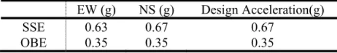
Table 1. Seismic data
EW (g) NS (g) Design Acceleration(g)
SSE 0.63 0.67 0.67
OBE 0.35 0.35 0.35
2.3 Modeling and Analysis Execution
The modeling and the analysis of bullet resistant door is conducted using commercial software ANSYS 9.0[reference 4]. The characteristics of finite element model, the boundary condition, and the loading condition are summarized as below;
1) Element type: Shell63 2) Number of elements: 7688 3) Boundary condition
- All the connection areas to hinge are fixed.
- Locking pins of the inactive door have DOF(Degree Of Freedom), such as UX, UZ, ROTX, ROTZ fixed.
- Edge areas where inactive doors and active doors meet each other have Coupling DOF such as UZ. - Locking devices have Coupling DOF such as UY,
UZ, ROTY, ROTZ. 4) Loading Condition
- Horizontal design acceleration of SSE (=0.67 g in z-direction) is applied.
All the geometric boundary conditions are schematized in Fig. 1. The finite element model of bullet resistant door with the boundary condition is shown in Fig. 2. The mating parts of the reinforced frames and the door are modeled by sharing the coincident nodes so that the stiffness of mating part should be increased. To make it easy to apply the boundary condition, the number of nodes constituting the finite element model is arranged by certain rule. The static analysis is applied to the above door modeling under the specified acceleration condition.
Transactions of the Korean Nuclear Society Autumn Meeting Busan, Korea, October 27-28, 2005
Figure 1. Diagram for boundary condition
Figure 2. FE model of bullet resistant door with boundary condition and loading condition
3. Results
3.1 Displacement, Stress, and Reaction Results
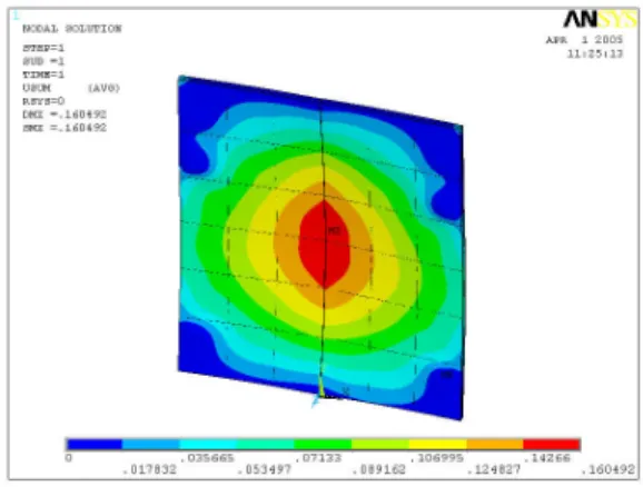
The displacement contour, the stress contour, and the reaction on hinge locations are calculated and shown in Fig. 3, Fig. 4, and Table 2. The maximum displacement occurs in the middle of the door and the maximum stress in the hinge location. The reaction results in Table 2 shall be used for sub assemblies of each hinge in detailed design and evaluation.
Figure 3. Displacement of bullet resistant door (mm)
Figure 4. Effective stress of bullet resistant door (N/mm2)
Table 2. Reaction force and moment at the concerned location
NODE FX FY FZ MX MY MZ L.H.(AD) 18.44 -1415. 286.8 5.343 -1.238 0.0009 M.H.(AD) -143.3 973.0 421.0 -5.453 -2.218 -0.002 H.H.(AD) 124.9 470.6 78.26 -3.225 2.067 -0.0008 L.H.(ID) -123.7 -1433. 284.6 5.454 1.299 -0.0008 M.H.(ID) 56.75 962.0 432.5 -5.576 2.447 0.002 H.H.(ID) -340.0 442.5 75.73 -3.307 -2.027 0.001 L.P.(AD) 120.8 660.0 3.175 -0.005 L.P.(ID) 286.1 621.3 -2.973 0.012 Total Sum 0.00 -0.01 2860. -6.561 0.330 0.008
L.H.: Lowest Hinge, M.H.: Middle Hinge, H.H.: Highest Hinge, L.P.: Locking Pin, AD: Active Door, ID: Inactive Door,
3.2 Criteria and Evaluation
The maximum stress and the maximum displacement are shown in Table 3. The maximum stress is 6% and 12% of the stress intensity for OBE and SSE respectively.
Table 3. Maximum stress and maximum displacement of bullet resistant door
Operating Condition Max. Stress (MPa) Max. Displacement (mm) Stress Intensity OBE* 8.655 0.08 138** SSE 16.568 0.16 138**
* OBE results are calculated from SSE by 0.35/0.67.
** MDF A 240 Type 316 is substituted for ASTM A666 type 316.
ACKNOWLEGHMENT
The project has been carried out under the Nuclear R&D program by MOST
REFERENCES
[1] 10CFR 50, Appendix B.
[2] ASME NQA-1, 1989 Edition, Quality Assurance Program Requirements for Nuclear Facilities.
[3] ASME NQA-2, 1989 Edition, Quality Assurance Requirements for Nuclear Facility Applications.