P1-50 / Y.-K. Lee
IMID 2009 DIGEST •
Surface Discharge Characteristics of New Flat Fluorescent Lamp
Enhanced by MgO Nano-Crystals
Yang-Kyu Lee, Seung-Taek Heo, You-Kook Lee, and Dong-Gu Lee
1 Department of Information and Nano Materials EngineeringKumoh National Institute of Technology, Gumi, Gyungbuk 730-701, Korea Tel: +82-54-478-7739, 1E-mail: [email protected]
Keywords : Flat Fluorescent Lamp(FFL), Back Light Unit (BLU), MgO Nano-crystals
Abstract
It has been recently reported that nano-sized MgO single crystal powders emit ultraviolet by stimulation of electrons under vacuum condition. Therefore, in this study, nano-crystalline MgO powders were applied to a xenon plasma flat fluorescent lamp for LCD backlight to improve emission efficiency of the lamp by help of extra ultraviolet from nano-MgO. For comparison with nano-crystalline MgO powders, MgO nano-thin film was applied directly on phosphors inside a lamp panel through e-beam evaporation The luminance and efficiency of FFL with an addition of MgO nano-crystal powders on phosphors were improved by around 20%. Application of MgO thin film to phosphors worsened the emission characteristics of FFLs, even rather than FFL without MgO. The reason came from insufficient stimulation of phosphors by UV, crystallinity of MgO, and low secondary electron coefficient
1. Introduction
A xenon plasma flat fluorescent lamp (FFL) is advantageous to LCD backlight because of excellent emission uniformity compared to the line emission source of the conventional cold cathode fluorescent lamp (CCFL) [1] or the point emission source of light emitting diode. In addition, the xenon lamp does not contain mercury gas, which is environmentally hazardous [2,3]. In spite of these advantages, there is a barrier for the imminent commercialization to LCD backlight. Since the luminous efficiency of a xenon lamp is quite low compared to CCFL due to its low UV emission, it consumes more power and emits more heat.
It has been recently reported [4] that nano-sized MgO single crystals in range of a few hundred nanometer emits UV under vacuum by stimulation of electrons. MgO materials also have large secondary
electron yield, leading to more possibly UV emission from xenon plasma and have low sputter yield, leading to protective layer.
In this study, nano-sized MgO single crystal powders were applied over phosphors inside a lamp panel as shown in Fig. 1(a) to improve the luminous efficiency of xenon lamp by help of extra UV emission from MgO single crystals. For comparison of the panel with MgO single crystal powders, another panel was fabricated with nano-sized coating of MgO over phosphors by e-beam evaporation as shown in Fig. 1(b). Comparative results will be presented through emission characteristics of xenon lamps.
2. Experimental
PD-200 (Asahi glass) was used as a panel glass because it dose not deform even at firing temperature. Silver paste (Taiyo Ink) was used as an electrode material for good conductivity. To protect the electrode from ion bombardment, electrodes were covered with a dielectric material (Ildong Chemical). White phosphor used in this study is composed of
33% red (Y2O3:Eu), 33% green (LaPO4:Ce,Tb), and
34% blue (BaMgAl10O17:Eu) phosphors. Printing,
sealing, and gas control of panels were proceeded using screen printer (Bando Industrial), dispenser (Musashi Engineering), and sealing system (Avaco), respectively. For assembling FFL panel, silver electrodes, a white back dielectric layer (whiteback), and a phosphor layer were screen-printed on the rear glass and fired at 550, 450, and 570℃, respectively in sequence. On front glass, another phosphor layer was printed and fired. Both front and rear glasses were sealed at 450℃ and then pumped out under the
P1-50 / Y.-K. Lee
• IMID 2009 DIGEST
pressure of 10-3 torr at 150℃ for 60 min to completely remove organic residues. Xe gas was injected after
vacuuming 10-6 torr for efficient plasma discharge.
MgO nano-crystals (~200nm dia) were dispersed in methanol solution by sonication for several minutes and were sprayed over phosphors. The amount of the sprayed MgO powders varied from 0.05 g to 0.20 g on 8.5 cm x 7.5 cm emission area. The coverage area of the sprayed MgO powders was measured by an image analyzer as shown in Table 1. On another sample, MgO thin film (200nm thick) was deposited on phosphors by e-beam evaporation. The luminance characteristics of the two types of FFL were compared and characterized using a spectra-radiometer (Minolta, Cs-1000A) and a square pulse power supply (Ftlab, PDS-4000).
(a)
(b)
Fig. 1. Schematic diagram of xenon FFLs with (a) MgO nano-crystals and (b) MgO thin film.
3. Results and discussion
With increasing xenon gas pressure inside panels, the luminance and efficiency of FFLs were improved as shown in Fig. 2. When plasma was generated by electrons excited from an applied voltage, the luminance and efficiency are affected by gas pressure. As gas pressure increased, the collision between xenon atoms and electrons becomes remarkably frequent, leading to more emission of ultraviolet and stimulation of phosphors.
Table 1. MgO coverage area on 8.5 cm x 7.5 cm emission area.
MgO Spray Amount
MgO Coverage Area (%) 0.50 g 36 0.10 g 41 0.15 g 55 0.20 g 73
Gas Pressure ( torr)
0 20 40 60 80 100 L u mina nce ( cd/m 2 ) 0 2000 4000 6000 8000
Without MgO nano powder MgO layer coverage 36% MgO layer coverage 40% MgO layer coverage 55% MgO layer coverage 73%
(a)
Gas Pressure (torr)
0 20 40 60 80 100 E ffi ci enc y (l m/ W ) 0.0 0.5 1.0 1.5 2.0 2.5 3.0 3.5
Without MgO nano powder MgO layer coverage 36% MgO layer coverage 40% MgO layer coverage 55% MgO layer coverage 73%
(b)
Fig. 2. (a) The luminance and (b) efficiency of FFL with Xe gas pressure for different MgO nano-crystal coverage area (sustain voltage: 1.4 kV, frequency: 25 kHz, duty: 25%, dielectric layer: 150
P1-50 / Y.-K. Lee
IMID 2009 DIGEST •
MgO layer coverage (%)
0 20 40 60 80 Lum inanc e (c d/ m 2 ) 4000 4500 5000 5500 6000 6500 7000
Fig. 3. The luminance of FFL with MgO nano-crystals coverage area.
From Fig. 2 and Fig. 3, the luminance and efficiency of FFL increased up to MgO coverage of 40 %, and then abruptly decreased over 40% coverage. The more MgO nano-crystals on phosphors, the more emission of ultraviolet, but if MgO powers cover too many areas of phosphors, the stimulation of phosphors is more insufficient due to its shadow effect.
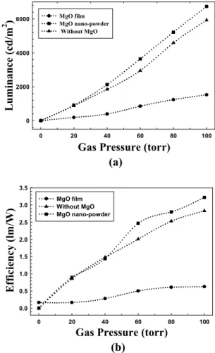
Figure 4 shows the luminance and efficiency of FFLs with MgO nano-crystals (40% coverage) and thin film. The luminance and efficiency for adding MgO nano-crystals were improved by around 20% rather than for no MgO crystals. MgO nano-crystal effect was notable over gas pressure of 40 torr. In contrast, for FFLs with MgO coating on phosphors, the emission characteristics were even worse than FFLs without MgO. Because the top surface area of phosphors on rear glass was wholly coated by the evaporated MgO film (i.e. large coverage area), the stimulation of phosphors by UV is somewhat insufficient. The crystallinity of MgO thin film is also quite crucial in emission characteristics.
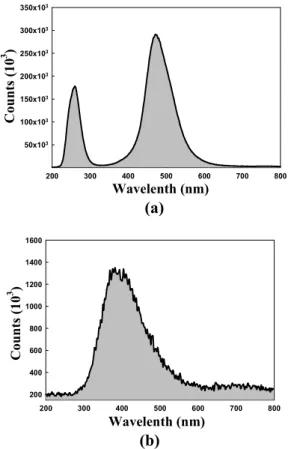
Figure 5 is cathode luminescence (CL) data of MgO nano-crystals and MgO thin films. MgO nano-crystal emitted ultraviolet in range of 200 nm to 300 nm. However, MgO thin film had no UV peak in CL data was not emitted ultraviolet. This phenomenon was interpreted through following expression.
g
E
hc
=
λ
where Eg is band gap energy of MgO (7.8 eV = 12.48
x 10-19 J), h is plank constant (6.63 x 10⁻³⁴ J·s), c is
velocity of light (3.8 x 10⁸ m·s). Therefore, if MgO
crystals have no defects (i.e. perfect crystals), it can
emit UV of a wavelength of 159 nm theoretically. As the defects in MgO crystals increase such as vacancy and dislocations, the emission wavelength becomes longer than 159 nm.
In XRD data as shown in Fig. 6, the crystallinity of MgO nano-crystal was superior to MgO thin film. This result matched well with CL results.
Figure 7 shows secondary electron coefficient (γ) of
MgO nano-crystal and thin film. The γ of MgO thin
film is lower than the γ of MgO nano-crystal, which
results are also related to its crystallinity.
Gas Pressure (torr)
0 20 40 60 80 100 L u minance (cd/m 2 ) 0 2000 4000 6000 MgO film MgO nano-powder Without MgO
(a)
Gas Pressure (torr)
0 20 40 60 80 100 E ffici ency (l m/W) 0.0 0.5 1.0 1.5 2.0 2.5 3.0 3.5 MgO film Without MgO MgO nano-powder (b)
Fig. 4. (a) The luminance and (b) efficiency of FFL with MgO nano-crystals (40% coverage) and thin film (sustain voltage:1.4 kV, frequency:25 kHz, duty: 25%, dielectric layer: 150 µm, and distance
P1-50 / Y.-K. Lee • IMID 2009 DIGEST Wavelenth (nm) 200 300 400 500 600 700 800 C ounts (10 3 ) 50x103 100x103 150x103 200x103 250x103 300x103 350x103
(a) Wavelenth (nm) 200 300 400 500 600 700 800 Counts (10 3 ) 200 400 600 800 1000 1200 1400 1600 (b)
Fig. 5. Cathode luminance data of (a) MgO nano-crystal and (b) MgO thin film.
Two Theta (degree)
50 60 70 80 Intens it y (Counts) 0 1000 2000 3000 4000 5000 (a)
Two Theta (deg)
50 60 70 80 90 In te nsi ty ( cou nt s) 0 20 40 60 80 100 120 (b)
Fig. 6. XRD data of (a) MgO nano-crystal and (b) MgO thin film
Applied Voltage (V) 120 140 160 180 Secon dary el ec tr on em issi on coef fi ci ent 0.02 0.04 0.06 0.08 0.10 0.12 MgO film MgO nano-powder
Fig. 7. Secondary electron emission coefficient of MgO nano-crystal and thin film.
4. Summary
The luminance and efficiency of FFL with an addition of MgO nano-crystal powders on phosphors were improved by around 20%. The MgO nano-crystal coverage of 40% over phosphors was found to give the best emission characteristics of FFL. Application of MgO thin film to phosphors worsened the emission characteristics of FFLs, even rather than FFL without MgO. The reason came from insufficient stimulation of phosphors by UV, MgO crystallinity, and low secondary electron coefficient.
Acknowledgement
The authors would like to acknowledge the financial supports by Research Fund, Kumoh National Institute of Technology.
5. References
[1] S. M. Hong and K. Y. Kim, J. of Inform. Displays,
5, pp56-62(2004).
[2] Y. Kim, IMID Technical Digest, pp25-29(2006).
[3] L. Schlig, L. Johnson, and W. King, SID
Technical Digest, pp53-57(2000).