냉동기에 의해 냉각되는 복사열차폐 최적설계
최연석
†․
Hongming Tang
*․
김동락
*․
양형석
*․
이병섭
*Design Optimization of Thermal Radiation Shield Cooled by Cryocooler
Y.S.Choi, H.Tang, D.L.Kim, H.S.Yang and B.S.Lee
Key Words: Cryogenic system(극저온시스템), Thermal radiation shield(복사열차폐), Cryostat(저온
용기), Cryocooler(냉동기), Superconducting magnet(초전도자석), Optimization(최적화)
Abstract
The design of thermal radiation shield cooled by a cryocooler is presented. This study is motivated mainly by our recent development of prototype superconducting magnet system for the Cyclotron K120. The superconducting magnet system is composed of the magnet cryostat, transfer line and supply cryostat. In order to minimize thermal radiation load, the superconducting coil form in the magnet cryostat is enclosed by the thermal radiation shield which is thermally connected to the first-stage cold head of a two-stage cryocooler in the supply cryostat. Since the supply cryostat is located far from the magnet cryostat large temperature gradient along the thermal shield is unavoidable. In this paper, the thermal radiation shield is optimized to minimize temperature gradient with taking into account the cryogenic load, system structure and electrical load. The effect of heat source from thermal conduction through mechanical supports on the temperature distribution of thermal radiation shield is also discussed.
†
한국기초과학지원연구원, 물성과학연구부 E-mail : [email protected] TEL : (042)865-3913 FAX : (042)865-3610*
한국기초과학지원연구원, 물성과학연구부1. 서 론
초전도자석을 이용하여 고자기장을 발생시키는 다양한 연구장비는 생물, 화학, 물리 뿐만아니라 재료분야의 분석에 많이 사용되고 있다. 의료분 야에서는 초전도자석을 이용하는 MRI가 이미 상 용화 되었고, 최근에는 초전도자석을 이용한 사 이클로트론이 전자석에 비해 가속에너지 대비 소 형화가 가능하므로 많은 관심을 받고 있다(1) . 한국원자력의학원에서는 의료용 차세대 사이클 로트론 K120을 개발하는 프로그램을 시작하였다 (2) . 한국기초과학지원연구원은 이 프로그램에서 3.5 테슬라 초전도자석 시스템 개발 업무를 담당 하고 있다. 초전도자석을 극저온으로 유지하기 위하여 상온으로부터 침입하는 복사열전달양을 최소화시키기 위하여 복사열차폐를 설치하는데, 최근에는 액체질소를 사용하는 대신에 2단 냉동 기의 1단 냉동부를 복사열차폐에 연결하여 사용 하고 있다. 하지만 공간 및 자기장 제약 때문에 냉동기는 초전도자석으로부터 멀리 떨어져 있어 야 하며, 따라서 복사열차폐에는 피할 수 없는 온도구배가 발생한다. 본 연구에서는 고자기장용 초전도자석 시스템 에서 냉동기에 의해 냉각되는 복사열차폐의 최적 설계 방법을 소개 한다. 최적 설계방법을 현재 진행중인 초전도 사이클로트론 시스템에 직접 적 용하여 설계의 타당성을 검증해 보고자 한다.2. 극저온 냉각시스템
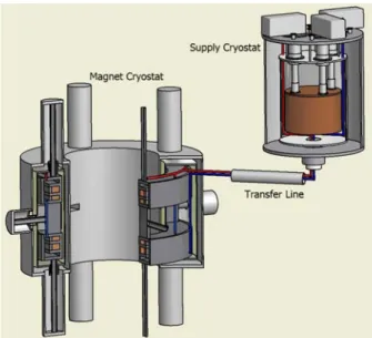
대한기계학회 2008년도 추계학술대회 논문집 2171Fig. 1 Superconducting magnet system for
Cyclotron K120
그림1에서 보는 바와 같이 사이클로트론용 초 전도자석 시스템은 자석 저온용기(Magnet Cryostat), 연결부위(Transfer Line) 그리고 냉각 저 온용기(Supply Cryostat)로 구성되어 있다. 자석 저 온용기안에는 두 셋트의 초전도코일이 용기의 중 앙에 위치하고 있고, 8개의 수직지지대 및 4개의 수평지지대에 의해 지지되고 있다. 초전도코일 냉각을 위한 채널이 초전도코일 폼 외부에 설치 되고 액체헬륨은 채널내부를 통과하면서 초전도 코일을 냉각한다. 2단 냉동기는 냉각 저온용기의 상부에 설치되며, 초전도코일로부터 회수된 헬륨 을 재응축 한다. 재응축된 액체헬륨은 초전도코 일을 냉각시키기 위해 자석 저온용기로 다시 공 급된다. 따라서 냉각시스템은 밀폐시스템이다. 순 환하는 헬륨은 초전도코일에서 발생하는 열을 흡 수하고 체적력내에서 열적으로 유도된 밀도차에 의해 발생하는 부력의 결과 그 열을 냉각 저온용 기에 있는 냉동기에 전달한다(3-5) . 복사열차폐는 초전도코일 및 순환하는 액체헬륨을 극저온으로 유지하기 위하여 에워싸고 있으며, 냉각 저온용 기에 위치한 2단 냉동기의 1단 냉동부에 연결되 어 있다.
3. 복사열차폐 설계
3.1 해석 모델 그림2는 사이클로트론용 복사열차폐 해석 모델Fig. 2 Model of thermal radiation shield
Fig. 3 Thermal conductivity of various copper and
aluminum alloy 이다. 냉각 저온용기내 복사열차폐 상부가 냉동 기와 연결되어 있으므로, 이 부분이 흡열원(Heat sink) 이고, 상온의 저온용기로부터 복사열차폐로 일정한 복사열전달이 진행된다(6) . 복사열차 폐를 기계적으로 지지하기 위한 지지대를 통하여 상온으로부터 전도열전달이 진행되며, 따라서 지 지대와의 연결부가 발열원(Heat source) 이 된다. 복사열차폐는 기계적, 열적 측면을 고려하면 여러 재질을 이용하여 만들 수 있으나, 본 연구 에서는 가장 일반적으로 사용하는 구리 및 알루 미늄 합금을 고려하기로 한다. 그림3은 구리 및 알루미늄 합금의 열전도도를 온도의 함수로 그린 그림이다. 2172
Fig. 4 Representative temperature distribution along
the thermal radiation shield
Material T1 T2 T3 T4 Al 1100 45 47.18 57.92 59.56 Al 3003 45 52.09 81.22 85.21 Al 6061 45 58.96 103.46 109.04
Table 1 Temperature distribution in thermal
radiation shield (t=5 mm, Q=1W/m2, unit:K)
Thickness T1 T2 T3 T4 2 mm 45 50.55 80.8 85.97 4 mm 45 47.74 61.4 63.57 6 mm 45 46.82 55.64 56.98
Table 2 Temperature distribution in thermal
radiation shield (Al 1100, Q=1W/m2, unit: K)
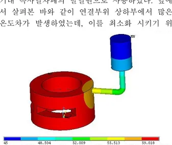
3.2 온도분포 상용프로그램인 ANSYS를 이용하여 복사열차 폐의 온도분포를 계산하였다. 본 설계에서 가능 한 변수는 열차폐의 두께 및 재질, 상온으로부터 복사열전달양, 그리고 지지대를 통하여 침입하는 전도열전달양 이다. 그림4는 복사열차폐의 재질 이 Al1100 이고 두께가 5 mm 일 때 복사열차폐 의 대표적인 온도분포 이다. 2단 냉동기의 1단 냉동부의 온도를 45 K 로 가정할 때 냉동부로부 터 가장 먼 곳의 온도가 가장 높으며, 그 값은 76.9 K 로 약 21.9 K 의 온도차가 발생함을 알 수 있다. 복사열차폐의 두께가 5 mm, 단위면적당 복사 열전달양이 1.0 W/m2 일 때 각각의 재질에 따른 온도분포를 표1에 정리해 보았다. 표1에서 T1,T2,T3 그리고 T4는 각각 냉동부의 온도, 연결 부위 상단의 온도, 연결부위 하단의 온도 그리고 자석 저온용기내 복사열차폐의 가장 먼곳의 온도 를 의미한다. Al 1100의 경우가 Al 3003 와 Al 6061 에 비해 온도차가 작음을 알 수 있으며, 연 결부위 상하부 사이의 온도차(T3-T2)가 상대적으 로 다른부위의 온도차보다 크다는 것을 알 수 있 다. 복사열차폐의 재질이 Al 1100 이고, 단위면적 당 복사열전달양이 1.0 W/m2 일 때 복사열차폐의 두께를 변화시켰을때의 온도분포를 표2에 정리하 였다. 복사열차폐의 두께가 증가함에 따라 온도 구배가 감소함을 알 수 있다. 하지만 두께가 증 가함에 따라 온도구배 감소폭은 점점 줄어드는 것을 알 수 있고, 두꺼운 재질의 가공성을 함께 고려해야 한다. 3.3 최적설계 복사열차폐의 두께, 재질 및 단위면적당 복사 열전달양을 변화시키면서 복사열차폐에서 발생하 는 온도구배를 구해 보았다. 30장의 MLI를 사용 하였을 경우 단위면적당 복사열전달양은 1.0 W/m2 이고, 가공성 및 소재의 용이성 등을 고려 하여 재질은 Al 1100, 두께는 5 mm로 결정하였 다. 지지대를 통한 전도열전달양은 한 개의 지지 대에 0.45 W 의 열침입이 발생하며 자석 저온용 기내 복사열차폐의 발열원으로 사용하였다. 앞에 서 살펴본 바와 같이 연결부위 상하부에서 많은 온도차가 발생하였는데, 이를 최소화 시키기 위
Fig. 5 Temperature distribution when the thermal
radiation shield is optimized
하여 그림3에서 보는 바와 같이 알루미늄보다 열 전도도가 높은 구리를 연결부위에 사용하여 온도 차를 최소화 하였다. 최적설계된 복사열차폐의 해석결과를 그림5에 그렸다. 냉동기 냉동부와 가 장먼곳의 온도차(T4-T1)은 약 15.8 K 이고, 이는 복사열차폐 온도설계값 60 K 이하를 만족시킨다. 초전도코일을 통전될 경우 발생하는 와전류 (Eddy current)를 최소화시키기 위하여 복사열차폐 를 중심축과 평행하게 두 개의 부분으로 나누었 다.
4. 결 론
사이클로트론용 초전도자석을 극저온으로 유지 시키기 위하여 저온용기내에 설치할 복사열차폐 를 설계하였다. 냉동기에 의하여 냉각되기 때문 에 복사열차폐에서 발생하는 온도구배를 최소화 시키기 위하여 상대적으로 가벼운 Al 1100을 사 용하였고, 구리 (RRR=100)를 연결부위에 사용하 여 복사열차폐가 약 60 K 이하를 유지하도록 설 계하였다. 초전도자석 시스템내에서 발생하는 와 전류를 최소화시키기 위하여 복사열차폐를 두 부 분으로 나누었다. 본 연구의 설계결과를 이용하 여 사이클로토론용 초전도자석 시스템을 제작할 예정이다.후 기
This work is supported by the KBSI grant T28051.
참고문헌
(1) Klein, H., Baumgarten, C., Geisler, A., Heese, J., Hobl, A., Krischel, D., Schillo, M., Schmidt, S., Timmer J., 2005, "New superconducting cyclotron driven scanning proton therapy systems," Nuclear Instruments and Methods in Physics Research B, Vol. 241, pp. 721-726.
(2) Choi, Y.S., Kim, D.L., Yang, H.S., Lee, B.S., 2008, "Study on the heat transfer in the closed-loop of liquid helium," presented in ICEC22-ICMC2008, Paper No. TH-C2-B10
(3) Maiani. M., de Kruijf, W.J.M., Ambrosini, W.,
2003, "An analytical model for the determination of stability boundaries in a natural circulation single-phase thermosyphon loop," Heat and Fluid Flow, Vol. 24, pp. 853-865.
(4) Misale, M., Garibaldi, P., Passos, J.C., Ghisi de Bitencourt, G., 2007, "Experiments in a single-phase natural circulation mini-loop," Experimental Thermal and Fluid Science, Vol. 31, pp. 1111-1120.
(5) Vijayan, P.K., 2002, "Experimental observations on the general trends of the steady state and stability behaviour of single-phase natural circulation loops," Nuclear Engineering and Design, Vol. 215, pp. 139-152.
(6) Incropera, F.P. and DeWitt, D.P., Fundamentals of Heat and Mass Transfer, John Wiley & Sons, 1996.