ICCAS2005 June 2-5, KINTEX, Gyeonggi-Do, Korea
Extension of Range Migration Algorithm for Airborne SAR Data Processing
Hee-Sub Shin, Won-Gyu Song, Jun-Won Son, Yong-Hwan Jung, and Jong-Tae LimDept. of EECS and Radiowave Detection Research Center, KAIST. Daejeon, Korea Tel: +82-42-869-3441; Fax: +82-42-869-3410
Email: [email protected], w [email protected], [email protected], [email protected], [email protected] Abstract: Several algorithms have been developed for the data processing of spotlight synthetic aperture radar (SAR). In particular, the range migration algorithm (RMA) does not assume that illuminating wavefronts are planar. Also, a high resolution image can be obtained by the RMA. This paper introduces an extension of the original RMA to enable a more efficient airborne SAR data processing. We consider more general motion and scene than the original RMA. The presented formulation is analyzed by using the principle of the stationary phase. Finally, the extended algorithm is tested with numerical simulations using the pulsed spotlight SAR.
Keywords: Spotlight Synthetic Aperture Radar, Range Migration Algorithm
1. Introduction
A SAR is a powerful remote sensing technique that allows the generation of microwave images of the earth’s surface, independently of weather condition and sun illumination. In particular, the spotlight SAR is able to obtain a high geomet-ric azimuth resolution by steering the radar antenna beam during the raw data acquisition interval, to always illumi-nate the same area on the ground. This azimuth steering allows the sensor to obtain a longer synthetic array without increasing the real antenna azimuth size.
Several algorithms have been developed for the reconstruc-tion of spotlight SAR raw data. Each has its own advantages and shortcomings. Carrara et al. [1] give a comprehensive review of the polar format algorithm (PFA), chirp scaling al-gorithm (CSA) and range migration alal-gorithm (RMA). The RMA is sometimes called the ω-k algorithm [2]. First, the PFA is well known for processing spotlight SAR data. This algorithm involves the assumption that the spherical wave-fronts of the radar pulses can be approximated by planar wavefronts around the scene center. While these approx-imations are often quite good for small target scenes im-aged by airborne platforms, for larger scenes, the approxi-mations lead to errors in parts of the scene far away from the scene center. The Extended Chirp Scaling (ECS) algo-rithm is proven to be very powerful in the algoalgo-rithm’s ease of implementation but does not provide the exact solution in the focusing procedure due to approximations made in chirp scaling processing. As a result of this, the introduced phase errors are limiting the maximum achievable along track reso-lution [4]. The RMA can reconstruct exactly the reflectivity function of targets. Also, this algorithm has the advantages that range cell migration (RCM) can be compensated for all targets within the scene and that it can handle high squint angles and wide apertures accurately [1]-[3]. However, since the RMA assume that the SAR sensor traverses a straight-line flight path parallel to the azimuth axis, there are limi-tations in performing a real motion of airborne SAR. This research was supported by the Agency for Defense Development, Ko-rea, through the Radiowave Detection Research Center at Korea Advanced Institute of Science & Technology.
In this paper, we propose an extension of the original RMA to enable a more efficient method of raw data processing. Moreover, in order to test processing algorithms, we design a raw signal simulator. In the simulator, the SAR raw sig-nal is computed via a superposition integral in which the reflectivity map is weighted by the pulsed SAR system.
2. Signal Model
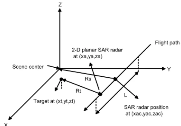
The geometry model in Figure 1 provides the basis for a simple SAR signal model to analyze the RMA. The SAR sensor travels an area during a synthetic aperture length L. The radar has a 2-D planar aperture. Also, the radar trans-mits and receives pulses at a fixed pulse repetition interval to maintain uniform spatial sampling along the flight path. Also, we assume that small deviation in the range direction exists and the airborne SAR is equipped with exact global positioning system (GPS). X Z Y Flight path L Target at (xt,yt,zt)
SAR radar position at (xac,yac,zac) 2-D planar SAR radar
at (xa,ya,za)
Rs Rt Scene center
Figure 1: Imaging geometry model
The X axis of this system is parallel to the azimuth direction. The fixed slant range distance between the center position of the flight path, i.e. (xac, yac, zac) and the scene center is Rs.
Point target analysis assumes that there is a single point tar-get within the imaged scene at coordinates (xt, yt, zt). The
distance Rt between the radar and this target varies as a
function of the SAR sensor position.
We introduce the extended RMA for a SAR system
ing a linear FM (chirp) waveform. In the geometry model of Figure 1, the SAR system transmits pulses at position (xa, ya, za) along the flight path. If there is a point target
located at (xt, yt, zt) with reflectivity function ρ(xt, yt, zt),
then the received signal is sr(n, t) = ρ(xt, yt, zt)ej2πfc(t−
2Rt
c )ejπγ(ˆt−2Rtc )2 (1) The quantity fcrepresents the center transmit frequency, c
is the speed of microwave, γ is the chirp rate and the symbol ˆ
t is defined by ˆt = t − nT , where n is discrete pulse number
and T is the period between successive pulse transmissions. Also, Rtis the range between the radar and the point target,
i.e.,
Rt=
p
(xa− xt)2+ (ya− yt)2+ (za− zt)2 (2)
We use the following reference signal with the constant ref-erence range Rs
sref(n, t) = ej2πfc(t−
2Rs
c )ejπγ(ˆt−2Rsc )2 (3) If we demodulate the received signal (1) using the reference signal (3), the resulting signal is
s(xa, ya, za, ˆt) = ρ(xt, yt, zt)ejΦ(xa,ya,za,ˆt) (4)
with Φ(xa, ya, za, ˆt) = −4πγc (fγc+ˆt−2Rcs)(Rt−Rs)+4πγc2 (Rt−
Rs)2 Also, since the residual video phase term can be
re-moved by the preprocessing of range deskew, we obtain the following phase
Φ(xa, ya, za, kr) = −kr(Rt− Rs) (5)
where kr = 4πγc (fγc + ˆt − 2Rcs). For simplicity, we assume
the backscattered amplitude and phase characteristic of the point target do not vary with frequency and other effect.
3. Main Results
3.1. Overview of Extended RMA
This section provides a simple overview of the extended RMA and illustrates its basic operation. The block diagram in Figure 2 provides the basis for image reconstruction pro-cessing via the extended RMA. After the conjugate opera-tion, we perform the 2-D Fourier transform with respect to xa and za for the collected SAR signal. Thereafter, we use
the matched filter to correct all range curvature of targets. Also, after Stolt interpolation, we reconstruct the complex image via 3-D inverse FFT with upsampling to avoid alias-ing due to compression.
3.2. 2-D Fourier Transform Analysis From (4) and (5), we obtain
s(xa, ya, za, kr) = ρ(xt, yt, zt)e−jkr(Rt−Rs) (6)
Also, from the conjugate operation of (6), we obtain the following equation s1(xa, ya, za, kr) = ρ(xt, yt, zt)ejkr(Rt−Rs) (7) Two dimensional Fourier Transform Matched filter Exp(krRs-ya srqt(kr^2-kx^2-kz^2)) Stolt interpolation ky=srqt (kr^2-kx^2-kz^2) Three dimensional Inverse FFT with upsampling
Reflectivity image Preprocessing Collected SAR signal
s1(xa,kr,za) s(xa,kr,za) S1(kx,kr,kz) S2(kx,kr,kz) S2(kx,ky,kz) rho(xt.yt.zt) Extended RMA Complex conjugate operation
Figure 2: Block diagram of extended RMA
The 2-D Fourier transform of (7) with respect to xa and za
yields
S1(kx, kr, kz) = Z Z
s1(·)e−(jkxxa+jkzza)dx
adza (8)
To evaluate (8), using the method of stationary phase [5], we determine the stationary points of its phase. The phase function ϕ corresponds to
ϕ(xa, ya, za, kr) = krRt− kxxa− kzza (9)
where Rt= p
(xa− xt)2+ (ya− yt)2+ (za− zt)2.
Substituting Rt into (9) and equating the first derivative to
zero gives ∂ϕ(xa, ya, za, kr) ∂xa (x0, z0) = kr(x0− xt) Rt0 − kx= 0 (10) ∂ϕ(xa, ya, za, kr) ∂za (x0, z0) = kr(z0− zt) Rt0 − kz= 0 (11) where Rt0= p (x0− xt)2+ (ya− yt)2+ (z0− zt)2.
Solving (10) and (11) for x0 and z0respectively, yields
x0 = p kx(ya− yt) kr2− kx2− kz2 + xt (12) z0 = p kz(ya− yt) kr2− kx2− kz2 + zt (13)
as the stationary points. The phase of S1(kx, kr, kz) is
Φrma(kx, kr, kz) = krRt− kxxa− kzza− krRs (14) 858
Substituting the value x0 and z0 for xa and za in (14), we obtain Φrma(·) = −kxxt− kzzt− krRs +(ya− yt) p kr2− kx2− kz2 (15)
after some manipulation.
Also, we assume that the amplitude factor is suppressed in the reflectivity function. Thus, we obtain the following signal S1(kx, kr, kz) = ρ(xt, yt, zt)ejΦrma (16)
3.3. Matched Filtering Analysis
The second step is a phase compensation to the 2-D trans-formed signal. The matched filter is defined as follows
Φmf(kx, kr, kz) = −ya p
kr2− kx2− kz2+ krRs (17)
This matched filtering operation corrects the range curva-ture of all targets at the same range as scene center. 3.4. Stolt Interpolation Analysis
A change of variables, known as the Stolt interpolation is defined as follows
ky=
p
kr2− kx2− kz2 (18)
After application of the Stolt interpolation, the signal be-comes
S2(kx, ky, kz) = S1(kx, kr, kz) × eΦmf(kx,kr,kz)
= ρ(xt, yt, zt)e−j(kxxt+kyyt+kzzt) (19)
Thus, if we consider a scene with a distributed target, we can obtain the following desired signal
Srma(·) = Z Z Z
ρ(·)e−j(kxxt+kyyt+kzzt)dx
tdytdzt (20)
Thus, from (20), if we perform compression via a three-dimensional inverse FFT, we can reconstruct the scene im-age.
4. Simulation Results
We tested the extended RMA with simulated data and com-pared the results with the original RMA. The basic simula-tion parameters are as follows:
• Center frequency (fc) : 1010Hz • Synthetic aperture length (L) : 100m • Bandwidth (B) : 133.5 × 10⁶Hz
• Pulse repetition frequency (P RF ) : 1000Hz • Platform velocity (v) : 400m/s
• Pulse width (TP) : 10−6sec • Chirp rate (γ) : B/Tp
• Speed of light (c) : 2.99792458 × 10⁸m/s
• Complex sampling frequency (Fs) : 185.0 × 10⁶Hz
As shown in Figure 3, for simplicity, there are five point targets with the same reflectivity magnitudes and zt = 0 in
the scene. Also, zac is a constant value 2000m. Also, due
to high atmospheric turbulence, we assume that there are
2m deviation in the range direction from the position xa=
L/2 (case 1) and 1 ∼ 3m deviations in the same direction from the position xa = L/4, L/2 and 3L/4 (case 2). We
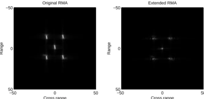
show some simulation results to verify the feasibility of our algorithm. As shown in Figs. 4−5, the extended RMA yields a better response as compared to the original RMA. Also, the targets can be mixed in the original RMA. However, as further works, we need to study the sidelobe reduction of the extended RMA. Reflectivity Map Range Cross range −50 0 50 −50 0 50 Original RMA Range Cross range −50 0 50 −50 0 50
Figure 3: Platform motion with constant ya
Extended RMA Range Cross range −50 0 50 −50 0 50 Original RMA Range Cross range −50 0 50 −50 0 50
Figure 4: Platform motion with variable ya(case 1)
Extended RMA Range Cross range −50 0 50 −50 0 50 Original RMA Range Cross range −50 0 50 −50 0 50
Figure 5: Platform motion with variable ya(case 2)
5. Conclusions
In this paper, the 2-D original RMA with a straight-line mo-tion of platform was extended. That is, we introduced the 3-D SAR reconstruction algorithm with more general flight path. Also, some additional terms were formulated by the method of stationary phase. Using the pulsed SAR simula-tor, we showed advantages of the extended RMA. Also, we will study the sidelobe reduction problem and motion error of other directions.
References
[1] W. G. Carrara, R. S. Goodman, and R. M. Majew-ski, Spotlight Synthetic Aperture Radar Signal Process-ing Algorithms, Artech House, 1995.
[2] C. Prati, A. Guarnieri, and F. Rocca, “Spotlight mode SAR focusing with the ω-k technique,” Proc. IGARSS, Espoo, Finland, pp. 631-634, June 1991.
[3] A. Reigber, A. Potsis, E. Alivizatos, N. Uzunoglu, and A. Moreira, “Wavenumber domain SAR focusing with integrated motion compensation,” Proc. IGARSS, 2003. [4] A. Moreira, J. Mittermayer, and R. Scheiber, “Ex-tended chirp scaling algorithm for air- and spaceborne SAR data processing in stripmap and ScanSAR imaging modes,” IEEE Transactions on Geoscience and Remote Sensing, Vol. 34, No. 5, pp. 1123-1136, Sep. 1996. [5] Born, M., and E. Wolf, Principles of optics :
elec-tromagnetic theory of propagation, interference and diffraction of light, Cambridge University Press, 1999.