전산해석을 이용한 착상이 핀튜브 열교환기 성능에 미치는
영향에 관한 연구
김성줄
†· 최호진
*· 하만영
*· 방선욱
**A study on the performance of the finned tube heat exchanger affected by the frosting
using CFD tool
Sung-Jool Kim, Hojin Choi, Man-Yeong Ha and Seon-Wook Bang
Key Words : Airside inlet temperature(공기측 입구온도), Airside inlet velocity(공기측 입구속도), Finned tube heat exchanger(핀튜브 열교환기), Fin pitch(핀피치), Fin thickness(핀두께), Frost thickness(서리두께)
Abstract
We conducted a study by computational simulation about the effects of frost thickness on the pressure drop and heat transfer characteristics as whole heat exchanger configuration changes. In order to perform the analysis for validation, we assumed that frost properties have constant values and the frost layers that are formed on the fin and tube surfaces are uniform. In order to find the constant thermal conductivity of frost layer, a variety of frost thermal conductivities are performed in our work and compared with the results by Lee et al. [4] and Yang et al. [5] proposed many experimental data about the 2-rows and 2-columns finned tube heat exchanger. The numerical results agreed well with the experimental data when frost conductivity is 0.07W/mK. After the validation had performed, we applied this procedure to the finned tube heat exchanger of domestic refrigeration and investigated the thermo-hydraulic characteristic of the heat exchanger affected by frost thickness according to the inlet velocities and temperatures of air considering the configuration change such as fin pitch.
기호설명 Dt : 튜브 지름 (mm) Df : 핀 두께 (mm) Dfr : 서리두께 (mm) P : 압력 (Pa) Pf : 핀피치(mm) Kfr : 서리 열전도도 (W/mK) Q : 열전달율 (W)
1. 서 론
최근 유가의 급등과 지구 온난화와 같은 환경적인 요인에 의해 냉동공조기의 효율에 관한 관심이 급증하고 있으며, 특히 열교환기의 효율 향상에 많은 투자가 이루어지고 있다. 가정용 냉장고 또는 에어컨 등에 주로 사용되는 핀-튜브 열교환기의 성능은 핀 형상, 핀과 튜브 피치, 튜브 열 수와 같은 설계 변수와 속도, 온도, 습도와 같은 다양한 유동 조건에 의해 영향을 받는다. 특히 열교환기가 빙점 이하 온도에서 작동하는 증발기에서는 열교환기 성능이 서리층에†
회원, 논문발표자의 소속 E-mail : [email protected] TEL : (051)510-3090 FAX : (051)515-3101*
부산대학교 기계공학부**
LG 전자 냉장고 연구실 대한기계학회 2008년도 추계학술대회 논문집의해서 큰 영향을 받는다. 열교환기 튜브 및 핀 표면에 형성된 서리층은 열교환기의 열저항과 압력강하를 증가시켜 열교환기 전체 성능을 감소시키는 역할을 하기 떄문에, 증발기에서 착상된 서리층을 고려한 연구는 매우 중요하다. 이러한 중요성 때문에 예전부터 착상조건을 고려한 다양한 열교환기에 대해 많은 연구가 수치적 혹은 실험적으로 수행되어 왔다.[1-12] 그러나 열교환기 성능 해석과 관련된 많은 연구 중에서 전산해석을 이용한 핀튜브 열교환기 성능에 관한 연구[13-16]는 극히 드물다. Jang[13] 등은 다양한 튜브 열을 가지는 평판 핀-튜브 열교환기의 열전달과 유동에 대해 전산 및 실험 해석을 수행했다. Romero-Mendez[14] 등은 1 열 핀-튜브 열교환기에서 핀 간격의 영향에 관해 연구를 수행하였다. Leu[15] 등은 3 차원 난류 해석에 의한 전산 해석을 수행하였다. 그러나 Huang[16] 등을 제외하고는 착상조건을 고려한 핀-튜브 열교환기의 성능에 대해 전산해석을 수행한 논문은 거의 없다. Huang[16] 등은 4 열 핀-튜브 열교환기에서 서리 두께 효과를 고려하여 일정한 공기 체적과 변하는 공기 체적 조건에서 열적 특성에 대한 전산해석을 수행하였다. 그들은 단일 채널 유동 면적의 절반이 서리에 의해 막히기 전에 제상이 이루어져야만 한다고 주장하였다. 하지만 Huang 등은 열교환기의 일정 부분의 해석을 수행하였으며, 열교환기의 전체 형상 해석은 고려하지 않았다. 따라서 본 논문에서는 전체 열교환기 형상을 고려하여, 서리 두께가 열교환기 성능변화에 미치는 영향에 대하여 연구하였다. 본 연구에서는 열교환기 전체 형상에 대하여 전산해석하여 서리층 착상을 고려한 핀-튜브 열교환기 열전달 성능 감소 및 압력강하 특성을 연구함으로써, 핀-튜브 열교환기의 착상에 의한 성능 변화를 예측하는 것을 목표로 한다.
2. 수치기법
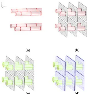
Fig. 1 에서 보여지는 핀-튜브 열교환기는 주로 양문형 냉장고에 사용되는 증발기중의 하나로 튜브는 엇갈림 배열로 되어있으며 튜브 직경과 (a) (b) (c) Fig. 1 Drawing for a finned tube heat exchanger (a) Left view, (b) Front view, (c) Used mesh튜브 종방향 피치는 각각 8mm 와 30mm 로 길이가 폭에 비해 상대적으로 큰 특성을 가진다. 착상된 열교환기의 전체 형상에 대하여 수치적으로 온도장 및 유동장을 해석하기 위해 본 연구에서 사용한 가정은 다음과 같다.[16] 1. 유동은 일정 물성치를 가지는 비압축성 유동이며 부력은 무시한다. 2, 서리층이 매우 천천히 성장하기 때문에 준정상상태 과정을 가정한다. 3. 핀과 튜브 표면에 형성되는 서리층들은 균일하며 준정상상태에서 일정한 두께를 가진다. 4. 서리층 내부에 열전달은 오직 열전도에 의해서만 일어나며 질량 전달은 무시한다. 본 연구에서는 착상된 복잡한 형상의 핀-튜브 열교환기의 유동장과 온도장을 해석하기 위하여 유한체적법에 기초한 상용 CFD 패키지인 Fluent 6.3 을 사용하였다. 소산항은 중앙차분법을, 대류항은 상류차분법을 사용하여 이산화하였으며, 열교환기 내의 핀 및 튜브 후류 영역의 난류를 고려하기 위하여 표준
k
−
ε
난류 방정식을 사용하였다. 열교환기 전체 크기에 비해 핀피치와 서리두께가 너무 작기 때문에 효율적으로 격자를 생성시키기 어렵다.
(a) (b)
(c) (d)
Fig. 2 The shape of meshed generated (a) in the tube, (b) in the fin, (c) in the frost layers of tube, (d) in the frost layers of fin
Fig. 2 는 튜브와 핀, 서리층에 생성된 격자 형태를 나타낸 그림으로, 형상의 복잡성 때문에 그림과 같이 본 연구에서는 unstructured 격자를 사용하였다. 모델링과 해석을 수행할 때 symmetric 경계조건을 사용하여 전체 열교환기의 절반을 고려하여 모델링 하였다. 본 연구에서 사용된 열교환기내 격자 수는 80 만~120 만개 사이로 격자 수는 서리층 두께에 의존한다. 서리층 두께가 열교환기 성능에 미치는 영향을 계산하기 위하여 본 연구에서는 서리층 두께를 0.0(무착상), 0.8, 1.6, 2.4mm 로 고려하였다. 본 연구에서 사용된 경계조건은 다음과 같다. 입구에서 속도와 온도는 일정하며, 사용된 수치는 일반 가정용 냉동실의 일반적인 속도인 1.0, 1.5, 2.0m/s, 온도는 252, 257, 262K 이다. 핀과 튜브, 서리층의 표면과 튜브 표면에서는 no-slip 경계조건을 사용하였으며, 튜브 표면 온도는 242K 로 고정하였다. 그 외 사용된 공기, 서리, 핀의 물성치는 표 1 과 같다.
Table 1 The material properties of air, fin and frost used in the present computation
Properties Fin Frost Air Density(kg/m3) 2719 200 1.27 Specific heat 871 1980 1006.4 Thermal conductivity (W/m·K) 202.4 0.07 0.0242 Dynamic viscosity - - 1.7×10 -5 같은 형상)에 대해 계산을 수행하고 실험결과와 비교하였다.표 2 에서 0.02, 0.07, 0.13 W/m·K 의 세 가지의 열전도도에 대하여 계산한 결과들을 서리두께에 대한 공기출구온도를 이용하여 실험결 과[4,5]와 비교하였다. (a) (b) Fig. 3 The Physical model of the Frosted finned tube heat
exchanger, (a) left view, (b) front view
표 2 에서 서리의 열전도도가 0.07 W/m·K 일 때 전산 결과가 실험 결과[5,6]와 6.3% 이내에서 결과가 잘 부합되는 것을 볼 수 있다. 따라서 본 연구에서는 이미 표 1 에서 나타낸 것처럼 서리층 열전도도 0.07 W/m·K 을 사용하였다. 표 3 은 본 전산해석의 격자 의존성에 관한 결과로서 Fig.1 에서 나타난 방향에 대하여 격자 크기를 조절하였을 때의 계산된 열전달율을 대상으로 비교하였다. 격자 크기가 x 축과 y-z 면 세 방향 모두 감소할 때 열전달율의 상대오차가 감소한다.
3. 결과 및 토론
본 계산의 유효성 검증과 서리의 열전도율을 결 정하기 위하여 Fig. 3 의 형상(Lee[4] 등과 Yang[5] 등에 의한 실험에 사용된 열교환기와Table 2 The Comparison of the present computation result for the outlet temperature of air as a function of the frost layer thickness with the experimental data using thermal conductivities
Air outlet temperature ( C), Relative error with Experiment (%) Frost thicknes s (mm) Exp. by [5] 0.02 fr k = kfr=0.07 kfr=0.13 0 - 2.21 2.21 2.21 0.8 2.87 3.81 ( 32.5%) 2.91 ( 1.3%) 2.68 ( 6.7%) 1.6 3.49 4.52 ( 29.6%) 3.27 ( 6.3%) 2.84 ( 18.6%) 2.4 3.57 4.95 ( 38.7%) 3.54 ( 0.9%) 2.97 ( 16.6%)
Table 3 Grid independence test
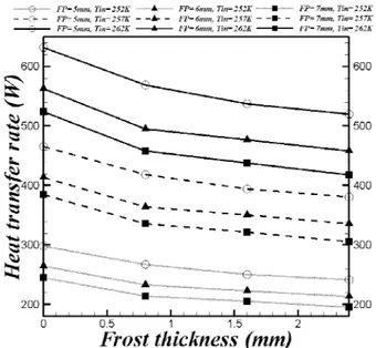
X-axis Spacing Size (mm) 2 1.5 1.1 0.9 0.8 0.7 Heat Transfer rate(W) 98.6 110.2 122.1 128.1 128.1 133.7 Relative Error (%) 10.51 9.76 4.70 2.47 1.77 YZ-Face Spacing Size (mm) 4 3.5 3 2.5 2 1.8 Heat Transfer rate(W) 128.6 129.4 133.7 134.6 136.0 138.1 Relative Error (%) 1.31 1.16 1.12 1.07 0.99 본 연구에서는 계산 비용을 고려하여 x 축에 0.7mm, y-z 면에 3mm 의 격자 간격을 사용했으며, 이 때의 열전달율의 오차범위는 2 % 이내이다. 결과적으로 위의 격자를 이용하여 Fig. 1(a)에서 보여지는 핀-튜브 열교환기의 격자 분포를 얻을 수 있다. Fig. 4 는 입구 속도가 2m/s 이고 튜브 온도가 243 K 일 때 입구온도와 핀 피치가 변화할 때, 서리층 두께에 대한 열교환기의 열전달율을 나타낸 그림이다. 서리층 두께가 증가하면, 서리층 두께 증가에 의해 야기된 전체 열저항이 증가하여 결과적으로 열전달율은 감소한다. 공기 입구 온도가 증가하면 공기와 튜브사이에 온도차가 증가하기 때문에 열전달율은 증가한다. 핀피치가 증가하면, 열전달 표면적의 감소로 인하여 열교환기의 전체 열전달율은 감소한다.
Fig. 4 The heat transfer rate of a finned tube heat exchanger as a function of the thickness of the frost layer for different inlet Temperature of 252, 257, 262K and different fin pitches of 5, 6 and 7mm when inlet temperature is 261K 입구 속도와 서리층 두께에 많이 의존한다. 서리층 두께가 증가하면 감소하는 유동단면과 더불어 공기 유동 속도는 증가하며 결과적으로 핀과 튜브에서 증가하는 대류 열전달 계수와 더불어 Rconv 은 감소한다. 이러한 결합된 Rcond 과 Rconv 의 효과는 서리층에 의한 열교환기 열전달율 변화를 결정한다. 공기 속도가 상대적으로 낮은 0.1m/s 에서 서리에 의한 열전달율은 변하지 않는다. 열교환기 입구 속도가 증가하면 Rconv 은 감소하며 Rcond 에 비해 상대적으로 작은 크기를 가진다.
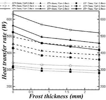
Fig. 5 The heat transfer rate of a finned tube heat exchanger as a function of the thickness of the frost layer for different inlet velocity of 1.0, 1.5 and 2.0m/s and different fin pitches of 5, 6 and 7mm when inlet temperature is 261K
Fig. 6 Pressure drops of a finned tube heat exchanger as a function of the inlet velocity for different frost thickness of 0.0, 0.8, 1.6 and 2.4mm and different fin pitch of 5, 6 and 7mm the heat exchanger
Rconv 은 같은 단면적을 가지는 경우 입구 속도 및 서리층 사이의 속도의 함수(또는 대류열전달 계수)로 나타낼 수 있으며, 입구 속도가 클수록 속도의 증가에 의한 Rconv 감소폭은 작아진다. 이러한 이유로 인해 Fig.5 와 같이 입구속도가 증가하면, 서리두께에 의한 열전달율 감소폭은 더욱 커진다. 열교환기의 압력강하는 입구속도와 입구 면적과 핀과 핀 사이의 면적 비인 차단비에 큰 영향을 받는다. Fig. 6 은 1.0, 1.5, 2.0m/s 의 다른 입구 속도에 대하여 서리층의 두께의 함수로써 열교환기의 압력강하를 나타낸 그림이다. 먼저 Fig. 6 에서 서리두께가 증가함에 따라 압력강하가 크게 증가하는 것을 관찰할 수 있다. 또한 피치에 따른 압력강하 차이도 크게 나는 것을 볼 수 있다. 이는 열교환기의 압력강하량이 속도 제곱에 비례하는 효과 때문이다. 피치간의 압력강하 차이는 초기 차단비 차이로 인해 발생하며 이와 결합하여 서리층 두께가 증가할 때 차단비는 더욱 커지므로 압력강하량은 더욱 증가한다.
4. 결론
본 연구는 착상 조건하에서 열교환기 형상 변화 에 따른 열전달 성능 변화와 서리두께에 따른 성 능 변화에 대해 초점을 맞추었다. 동일한 계산 영 역에서 서리두께를 고려하여 핀 피치의 영향과 서 리 두께의 영향에 대해 계산을 수행하였다. 본 연 구에서 일반적으로 알려진 바와 같이 핀피치가 증 가함에 따라 전열면적과 차단비의 감소로 인해 열 전달율 및 압력강하량은 작아진다. 또한 서리층이 충분히 두꺼울 때 서리층의 증가는 항상 압력강하 를 증가시키고 열전달율을 감소시킨다.후기
이 논문은 2007 년도 정부(교육과학기술부)의 재원으로 국제과학기술협력재단의 지원을 받아 수 행된 연구임 (No. K20702000013-07E0200-01310).This work was supported by the Korea
Foundation for International Cooperation of Science & Technology(KICOS) through a grant provided by the Korean Ministry of Education, Science & Technology(MEST) in 2007 (No. K20702000013-07E0200-01310).
참고문헌
(1) Tso, C. P., Cheng, Y. C. and Lai, A. C. K., 2006, “An improved model for predicting performance of finned tube heat exchanger under frosting condition, with frost thickness variation along fin,” Appl. Thermal Eng. Vol. 26, pp. 111-120.
(2) Xia, Y. and Jacobi, A. M., 2005, “Air-side data interpretation and performance analysis for heat exchangers with simultaneous heat and mass transfer,”
Int. J. Heat Mass Transfer Vol. 47, pp. 5089-5102.
(3) Lee, K. S., Jhee, S. and Yang, D. K., 2003, “Prediction of the frost formation on a cold flat surface,” Int. J. Heat Mass Transfer Vol. 46, pp. 3789-3796.
(4) Lee, K. S. and Park, H. Y., 1993, “Study on the frost formation of fin-tube evaporator”, LG Electronics Corp., 1st mid-term report
(5) Yang, D. K., Lee, K. S., and Song, S., 2006, “Modeling for predicting frosting behavior of a fin-tube heat exchanger,” Int. J. Heat Mass Transfer Vol. 49, pp. 1472-1479.
(6) Yun, R., Kim, Y. and Min, M., 2002, “Modeling of frost growth and frost properties with airflow over a flat plate,” Int. J. Refrig. Vol. 25, pp. 362-371.
(7) Chen, H., Thomas, L. and Besant, R. W., 2003, “Fan supplied heat exchanger fin performance under frosting conditions,” Int. J. Refrig. Vol. 26, pp. 140-149.
(8) Wu, X. M. and Webb, R. L., 2001, “Investigation of the possibility of frost release from a cold surface,” Exp. Thermal & Fluid Sci. Vol. 24, pp.151-159.
(9) Yang, D. K. and Lee, K. S., 2004, “Dimensionless correlations of frost properties on a cold plate,” Int. J.
Refrig. Vol. 27, pp. 89-96.
(10) Yang, D. K. and Lee, K.S., 2005, “Modeling of frosting behavior on a cold plate,” Int. J. Refrig. Vol. 28, pp. 396-402.
(11) Xiz, Y., Zhong, Y., Hrnjak, P. S. and Jacobi, A. M., 2006, “Frost, defrost, and refrost and its impact on the air-side thermal-hydraulic performance of louvered-fin, flat-tube heat exchangers,” Int. J. Refrig. Vol. 29, pp. 1066-1079.
(12) Ozkan, D. B. and Ozil, E., 2006, “Experimental study on the effect of frost parameters on domestic
refrigerator finned tube evaporator coils,” Appl.
Thermal Eng. Vol. 26, pp. 2490-2493.
(13) Jang, J. Y. and Wu, M. C., 1996, “Numerical and experimental studies of three-dimensional plate-fin and tube heat exchangers,” Int. J. Heat Mass Transfer Vol. 39, pp. 3057-3066.
(14) Mendez, R. R. and Sen, M., Yang, K. T. and McClain, R., 2000, “Effect of fin spacing on convection in a plate fin and tube heat exchanger,” Int. J. Heat
Mass Transfer Vol. 43, pp. 39-51.
(15) Leu, J. S., Wu, Y. H. and Jang, J.Y., 2004, “Heat transfer and fluid flow analysis in plate-fin and tube heat exchangers with a pair of block shape vortex generators,” Int. J. Heat Mass Transfer Vol. 47, pp. 4327-4338.
(16) Huang, J. M., Hsieh, W. C., Ke, X. J. and Wang, C. C. 2008, “The effects of frost thickness on the heat transfer of finned tube heat exchanger subject to the combined influence of fan types,” Appl. Thermal Eng. Vol. 28, pp. 728-737.