A New Approach to Adaptive Damping Control
for Statistic VAR Compensators Based on Fuzzy Logic
Alireza Sedaghati
Faculty of Electrical Engineering and Robotics, Shahrood University of Technology
(E-mail: [email protected] )
Abstract:This paper presents an approach for designing a fuzzy logic-based adaptive SVC damping In controller for damping low frequency power oscillations. Power systems are often subject to low Frequency electro-mechanical oscillations resulting from electrical disturbances. Generally, power system stabilizers are designed to provide damping against this kind of oscillations. Another means to achieve damping is to design supplementary damping controllers that are equipped with SVC. Various approaches are available for designing such controllers, many of which are based on the concepts of damping torque and others which treat the damping controller design as a generic control problem and apply various control theories on it. In our proposed approach, linear optimal controllers are designed and then a fuzzy logic tuning mechanism is constructed to generate a single control signal. The controller uses the system operating condition and a fuzzy logic signal tuner to blend the control signals generated by two linear controllers, which are designed using an optimal control method. First, we design damping controllers for the two extreme conditions; the control action for intermediate conditions is determined by the fuzzy logic tuner. The more the operating condition belongs to one of the two fuzzy sets, the stronger the contribution of the control signal from that set in the output signal. Simulation studies done on a one-machine infinite-bus and a four-machine two-area test system, show that the proposed fuzzy adaptive damping SVC controller effectively enhances the damping of low frequency oscillations.
Keywords: Low frequency oscillation; Damping controller; SVC; Fuzzy logic; Self tuning
1. INTRODUCTION
Power systems are often subject to low frequency electro-mechanical oscillations resulting from electrical disturbances. Generally, power system stabilizers are designed to provide damping against this kind of oscillations. Another means to achieve damping is to design supplementary damping controllers that are equipped with SVC. Various approaches are available for designing such controllers, many of which are based on the concepts of damping torque [1_/6] and others which treat the damping controller design as a generic control problem and apply various control theories on it [7_/10]. Linear controllers, being relatively simple to design, are widely used for such applications. However, controllers designed for a certain operating point may not act as effectively at other operating points.
In our proposed approach, linear optimal controllers and fuzzy logic are used jointly to provide (1) easiness in controllers are designed and then a fuzzy logic tuning mechanism is constructed to generate a single control signal. The underlying idea is that any operating condition partially belongs to two fuzzy sets: a ‘heavy’ and a ‘light’ operating condition set. First, we design damping controllers for the two extreme conditions; the control action for intermediate conditions is determined by the fuzzy logic tuner; the more the operating condition belongs to one of the two fuzzy sets, the stronger the contribution of the control signal from that set in the output signal.
As the first step in the design procedure, a series of evenly spaced operating conditions are selected. The two extremes are considered to fully belong to heavy and light condition sets, respectively, for which linear optimal controllers are designed. At any intermediate operating point, the output of the controller is a weighted sum of the outputs of these two controllers with the membership grades being the respective weighting coefficients. For the controller to approach the desired characteristics as close as possible, an algorithm based on a least squares error criterion is used to determine the best membership grades at all pre-chosen intermediate points. Using linear interpolation, two membership curves are
obtained. When used in real time, the two controllers work simultaneously and independently providing two damping signals. Fuzzy reasoning is then applied to determine how the two signals are to be mixed to generate one output signal for the operating condition at that time. As a result, an adaptive damping controller is acquired.
A detailed description of the proposed design procedure is given in Section 2. Simulation results are given for a single-machine-infinite-bus system and a 4-machine 13-bus system to demonstrate the effectiveness of
the proposed method.
2. PROPOSED CONTROLLER
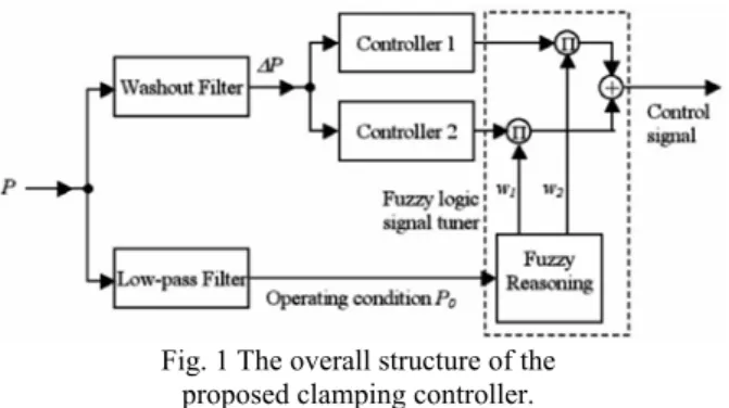
2.1 The structure of the controllerThe proposed damping controller consists of two linear controllers and a fuzzy logic-based signal tuner. These two controllers are designed for extreme operating conditions; therefore, they generate damping signals working best under those extreme conditions. It is generally reasonable to assume that a proper combination of them would work best for the conditions between these extreme ones. How far away the current condition is from each extreme case (or in fuzzy language, how much it belongs to one of the two fuzzy condition sets) determines how much the respective damping signal is weighted in the output. The fuzzy tuner combines the two individual signals in such a way that the signal fits the operating condition optimally. Fig. 1 illustrates the structure of the stabilizer, where the input P∆ is the transient component of the transmitted power through the bus where the SVC is located and the operating conditionP0is the steady-state component of that power. The steady-state and transient components are obtained by applying low-pass and high-pass filters, respectively, to the measured power signal in real time.
Generally the two linear controllers can be designed using different linear control theories. In this paper, a complex frequency domain-based optimal controller is adopted as discussed in a later subsection of the paper. The fuzzy logic tuner takes as its input the steady state value of the transmitted
power through the bus where the SVC is located and generates one output. For this input variable two fuzzy sets and accordingly two membership functions are defined. Two rules are defined as follows:
Fig. 1 The overall structure of the proposed clamping controller.
Rule (i): IF the operating condition is Ei; THEN the output signal is Si.
Here Eidenotes one of the defined fuzzy sets and Sidenotes the corresponding damping signal.
A Takagi-Sugeno fuzzy model is adopted [14], where Siis crisp and the defuzzification is simply a weighted summation expressed as follows:
(1)
i
w is the truth value (weight) of the ith rule, which is obtained by comparing the input variable against the membership function curve. Based on Eq. (1), the overall transfer function of the proposed controller is:
(2)
where Hi(s) is the transfer function of the ith linear controller (called basis functions hereafter).
From Eq. (2) we can see that the performance of the controller depends on the linear controllers Hi(s)and the membership functions. These two issues will be discussed in the following subsections.
2.2 Linear controller design
Consider a regulator problem as shown in Fig. 2. The output y of the plant G(s)is to be maintained as close as possible to the reference value r and the design goal of the controller
) (s
H is to minimize the integral square error:
(3)
Fig. 2 A regulator system.
Applying two-sided Laplace transformation and Parseval’s theorem, Eq. (3) is equivalent to
(4) Using Wiener-Hopf factorization [11], the optimal controller )H(s is found to be in the following form, assuming no right-hand side zeros are contained in the plant transfer function )G(s :
(5)
or if G(s)contains a right-hand side zero,
(6)
In the above equations G′(s)is identical to G(s)except that the right-hand zero is removed and h is a constant. In classical theory, the value of h depends on an energy constraint on the control signal; a zero value of h indicates that no energy constraint is imposed at all. In practice the value of
his not only a function of required energy, but also (and often more importantly) it is a function of side effects incurred by very high gain. In addition, the gain is subject to saturation in the signal path. With these factors considered, the value of
his often determined by simulation studies or other means. In our application, the reference signal is always zero, and the output of the plant y is P∆ (as shown in Fig. 3), which is expected to stay around zero. The way to determine the magnitude gains of the controller is by simulation. It was found that the integrator factor 1/s yields too high DC gain, which can cause unacceptable performance. Therefore, the expression of the controller was slightly modified to
(7)
where T is a large time constant.
Fig. 3 Modified system.
Due to its simplicity and effectiveness, a Prony method [12]
was used to obtain approximate low-order system models for )
(s
G .
2.3. Fuzzy logic signal tuner design and optimization
As discussed previously, membership functions affect the behavior of the proposed controller significantly and optimal controller performance can be achieved only with optimized membership functions. In our design, a simple linear quadratic optimization algorithm with a small step size [13] is used to determine the membership curves point by point. Interpolation is used to obtain the membership values for intermediate points.
Suppose P lies within a range from 0 P to min P . By using max the procedure introduced in the preceding subsection, we design a series of linear optimal controllers HDK(s) for
different operating conditions between Pminand Pmax as follows:
(8) where there are (m+1) operating points. The two basis functions are
(9) And
(10) For each integer k within the interval (0, m), we derive
k
w1, and w2,kin a procedure introduced in Ref. [13] so that )
(s
HDK can be approached optimally by the linear combination of the two basis functions:
(11)
The resultant w1,k and w2,k points form the membership curves for the fuzzy signal tuner; using linear interpolation between these points, the membership curves are obtained. When used on-line, the fuzzy signal tuner simply checks the value of P0 against the membership curves to decide the appropriate weights and then blends them as illustrated in
Fig. 1.
3. SIMULATION RESULTS
To test the performance of the proposed controller, simulation studies were performed on a one-machine infinite-bus system and a two-area 4-machine 13-infinite-bus system. Three-phase short-circuits were applied on the systems under different operating conditions. Faults occurred at the ends of transmission lines and then cleared after 0.05 s.
3.1. One-machine-infinite-bus system
The data for the one-machine infinite-bus system used is given in Ref. [13]. In this system, a bus is created in the middle of two parallel transmission lines to which an SVC is connected. The maximum transmittable power Pmax for this system is 4 p.u. (limited by stability) and we select
} 4 , 3 , 2 , 1 { ∈ k P .
After linear transfer functions for the plant G(s)are identified, the basis functions are obtained using Eq. (7) as follows:
(12)
(13)
The respective membership functions for the above basis functions are obtained as shown in Fig. 4. The time constant of the washout filter (Fig. 1) was set at 10 s. The overall transfer function of the controller is:
(14)
Fig. 4 Membership function curves.
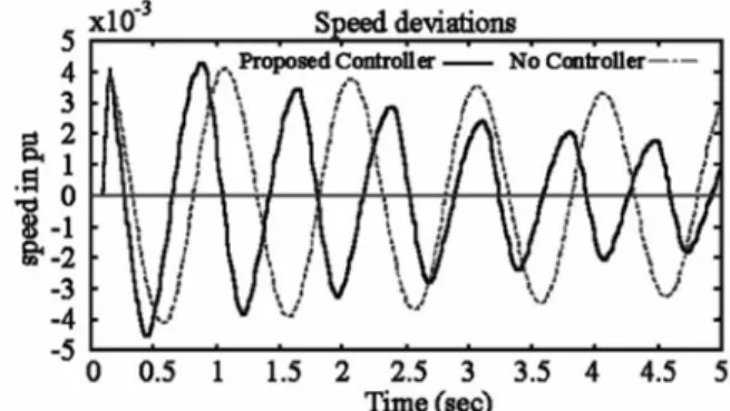
Fig. 5 Generator responses at operating point (P0=1.5 p.u.).
Fig. 6. Generator responses at operating point (P0=2.5 p.u.). With the proposed controller applied, Figs. 5 and 6 show the generator speed deviation as a function of time, for a light operating condition (P=/1.5 p.u.) and a heavier operating condition (P=/2.5 p.u.), respectively. For comparison, the generator responses are also shown when no controller is applied. It is clear that the proposed controller is effective under both operating conditions. However, it contributes more damping under the light condition. This is because when the transmitted power approaches the limit, it is harder to damp swings. From a viewpoint of optimal control theory,
) (s
G here exhibits a zero on the right-hand side of the s-plane which approaches the origin when the transmitted power grows. The closer the zero is to the origin, the larger is the corresponding time constant, and the larger (worse) is the achievable performance index [11].
3.2. A 4-machine-13-bus system
A two-area 4-machine, 13-bus system [10] (shown in
Fig. 7) was used to test the effectiveness of the proposed SVC controller in multi-machine systems. For this case, Pmax is 5.0p.u. and we select Pk∈{1,2,3,4,5}./
In a similar way, as explained above, the basis functions are obtained as follows:
(15)
(16) The respective membership functions for the above basis functions are obtained as shown in Fig. 8.
The time constant of the washout filter was set at 20 s. The transfer function of the controller is:
(17)
Figs. 9 and 11 show the speed deviations of all the generators as functions of time, for a light operating
Fig. 7 A two-area-four-bus system.
Fig. 8 Membership function curves.
condition (P =2.2 p.u.) and a heavy operating condition 0
(P =4.5 p.u.) respectively, both with the proposed SVC 0
controller acting. Notice that there is no infinite bus in the system and the speed deviations shown in the figures are relative to the center of inertia of these machines. For comparison, generator responses with no controller applied are also shown in Figs. 10 and 12 for light and heavy conditions, respectively. It is clear from these figures, that the proposed controller shows effective damping against power oscillations; it prevents the machines from going unstable, which would
otherwise occur if no supplementary damping controllers are present.
Fig. 9 Generator responses at operating point (P =2.2 p.u.) 0 with the controller.
Fig. 10 Generator responses at operating point (P =2.2 p.u.) 0 without the controller.
Fig. 11 Generator responses at op erating point (P =4.5 0 p.u.) with the controller.
4. CONCLUSION
The design of a fuzzy logic-based adaptive SVC damping controller for multi-machine power systems was presented in this paper. The controller uses the system operating condition and a Takagi-Sugeno type fuzzy logic signal tuner to blend the control signals generated by two linear controllers, which are designed using an optimal control method. Simulation results show that the proposed fuzzy adaptive damping SVC controller effectively enhances the damping of low frequency oscillations.
REFERENCES
[1] K.P. Padiyar, et al., Damping torque analysis of static Var system controllers, IEEE Transactions on Power Systems 6 (1991) 458_/ 465.
[2] E.V. Larsen, et al., Concepts for design of FACTS controllers to damp power swings, IEEE Transactions on Power Systems 10 (1995) 948_/956.
[3] P. Pourbeik, M. Gibbard, Damping and synchronizing torques induced on generators by FACTS stabilizers in multimachine power systems, IEEE Transactions on Power Systems 11 (1996) 1920_/1925.
[4] H.F. Wang, F.J. Swift, A unified model for the analysis of FACTS devices in damping power system oscillation. Part I: Single-machine infinite-bus power systems, IEEE Transactions on Power Delivery 12 (1997) 941_/946.
[5] H.F. Wang, F.J. Swift, M. Li, A unified model for the analysis of facts devices in damping power system oscillation. Part II: Multimachine power systems, IEEE Transactions on Power Delivery 13 (1998) 1355_/1362.
[6] H.F. Wang, F.J. Swift, Multiple stabilizer setting in multimachine power systems by the phase compensation method, Electrical Power and Energy Systems 20 (1998) 241_/246.
[7] E.Z. Zhou, Application of static Var compensators to increase power system damping, IEEE Transactions on Power Systems 8 (1993) 655_/661.
[8] J.R. Smith, Robust Var unit control strategies for damping of power system oscillations, Ph.D. dissertation, ECE Dept., Montana State University, Bozeman, 1988.
[9] T. Hiyama, W. Hubbi, T. Ortmeyer, Fuzzy logic control scheme with variable gain for static Var compensator to enhance power system stability, IEEE Transactions on Power Systems 14 (1999) 186_/191.
[10] G. Rogers, Power System Oscillations, Kluwer Academic, New York, 2000.
[11] D.A. Pierre, Optimization Theory with Applications, Wiley and Sons, New York, 1969.
[12] D. Trudnowski, J. Smith, T. Short, D. Pierre, An application of Prony methods in PSS design for multimachine systems, IEEE Transactions on Power Systems 6 (1) (1991) 118_/126.
[13] J. Lu, H. Nehrir, D. Pierre, A fuzzy logic-based adaptive power system stabilizer for multi-machine systems, Electric Power Systems Research Journal 60 (2001) 115_/121. [14] T. Takagi, M. Sugeno, Fuzzy identification of systems and its application to modeling and control, IEEE Trans-SMC 15 (1985).