J. Korea Society of Die & Mold Engineering, Vol.15 No.1, 2021 ISSN 2092-9692 . AI X-ray . X , AI X-ray . X X . X Cathode 1, : E-mail: [email protected] Filament ,
X-ray tube . Filament
, Anode Target X . 1% X 99% . Anode Cooling time , X X , X , X-ray tube . Lee X , X-ray tube 1), Anode
X-ray tube
1·
2·
1, 2A study on the analysis of heat flow in X-ray tube
Dong-Min Yun
1· Byung-Suk Seo
2· Yong-Han Jeon
Department of Fire Protection Engineering, Sangji University1, Department of Information Security, Sangji University2
(Received March 02, 2021 / Revised March 26, 2021 / Accepted March 31, 2021)
Abstract: As the aging ages, the disease also increases, and the development of AI technology and X-ray equipment used to treat patients' diseases is also progressing a lot. X-ray tube converts only 1% of electron energy into X-ray and 99% into thermal energy. Therefore, when the cooling time of the anode and the X-ray tube are frequently used in large hospitals, the amount of X-ray emission increases due to temperature rise, the image quality deteriorates due to the difference in X-ray dose, and the lifespan of the overheated X-ray tube may be shortened. Therefore, in this study, temperature rise and cooling time of 60kW, 75kW, and 90kW of X-ray tube anode input power were studied. In the X-ray Tube One shot 0.1s, the section where the temperature rises fastest is 0.03s from 0s, and it is judged that the temperature has risen by more than 50%. The section in which the temperature drop changes most rapidly at 20 seconds of cooling time for the X-ray tube is 0.1 seconds to 0.2 seconds, and it is judged that a high temperature drop of about 65% or more has occurred. After 20 seconds of cooling time from 0 seconds to 0.1 seconds of the X-ray tube, the temperature is expected to rise by more than 3.7% from the beginning. In particular, since 90kW can be damaged by thermal shock at high temperatures, it is necessary to increase the surface area of the anode or to require an efficient cooling system.
·
. Back
3), Lee MR fluid
polishing 4).
, X-ray tube Anode
. Anode . Lee 5). X-ray X-ray tube .
STAR-CCM+ X-ray tube Anode
( ) Anode
, Cooling time .
X-ray tube Anode
X-ray tube Rotor, Shaft, Bracket
, , Simcenter
STAR-CCM+ . X-ray tube Anode
Anode . :
∙ : time V : volume a : area vector : density : velocity :
⊗∙
∙
∙ : pressure : viscous stress tensor
∙
∙
∙
∙
: total energy : total enthalpy : heat flux
X-ray tube Anode Target
. Fig. 1 X-ray tube , Glass bulb
. X-ray tube Cathode
Cathode Filament
Anode Electronic beam . Electronic beam , X Anode Target . , 1% X . Anode Rotor Anode . Fig. 2
. X-ray tube Anode
.
Anode Insulation
oil .
Cathode Anode Target X
1% Target
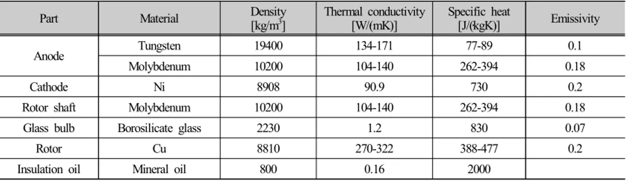
5W/m2K, 25℃ , Density, Thermal
conductivity, Specific heat Emissivity Table 1 .
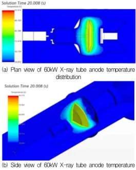
Fig. 3 One shot 0.1s Cooling time 20s , Fig.
4 60kW X-ray tube Anode (
) One shot 0.1s Cooling time 20s
. Anode
target One-shot 59.2℃ 377.9℃ Cooling
time 377.9℃ 72℃ . One shot 0.1s 0s 0.03s 55.6% 0.03s 0.06s 22.7%, 0.06s 0.1s 21.7% . 0s 0.03s . Cooling time 20s 0.1s 0.2s 66.6% , 3.0s 89.64%, 12s 95.61%, 20s 95.98% . 12s Cooling , One-shot 0s 20s 4.02% . 0s 59.2℃ One shot 0.1s ~ Cooling time 20s 72℃ 12.8℃ .
Part Material Density[kg/m3] Thermal conductivity[W/(m〮K)] Specific heat[J/(kg〮K)] Emissivity
Anode Tungsten 19400 134-171 77-89 0.1
Molybdenum 10200 104-140 262-394 0.18
Cathode Ni 8908 90.9 730 0.2
Rotor shaft Molybdenum 10200 104-140 262-394 0.18
Glass bulb Borosilicate glass 2230 1.2 830 0.07
Rotor Cu 8810 270-322 388-477 0.2
Fig. 5 One shot 0.1s Cooling time 20s , Fig.
6 75kW X-ray tube Anode (
) One shot 0.1s Cooling time 20s
. Anode target One-shot 67.3℃ 465.6℃ Cooling time 465.6℃ 82.23℃ . One shot 0.1s 0s 0.03s 55.7% 0.03s 0.06s 22.6%, . 0s 0.03s . Cooling time 20s 0.1s 0.2s 66.7% , 3.0s 90.09%, 12s 95.89%, 20s 96.25% . 12s Cooling , One-shot 0s 20s 3.75% . 0s 67.3℃ One shot 0.1s ~ Cooling time 20s 82.23℃ 14.93℃ .
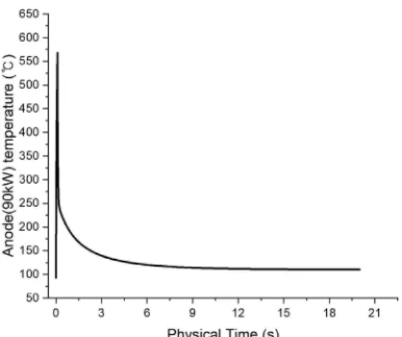
Fig. 7 One shot 0.1s Cooling time 20s , Fig.
8 75kW X-ray tube Anode (
) One shot 0.1s Cooling time 20s
. Anode
target One-shot 93℃ 567℃ Cooling
time 567℃ 110.21℃ . One shot 0.1s 0s 0.03s 54.9% 0.03s 0.06s 23.4%, 0.06s 0.1s 21.7% . 0s 0.03s . Cooling time 20s 0.1s 0.2s 67.68% , 3.0s 90.17%, 12s 96.01%, 20s 96.15% . 12s Cooling , One-shot 0s 20s 3.85% . 0s 93℃ One shot 0.1s ~ Cooling time 20s 110.21℃ 17.21℃ .
X-ray tube Anode
( ) 60kW, 75kW, 90kW
Simcenter STAR-CCM+ . 1) Simcenter STAR-CCM+
X-ray Tube Anode .
2) X-ray tube One shot 0.1s
0s 0.03s ,
50% .
3) X-ray tube Cooling time 20s
0.1s 0.2s
, 65%
.
4) X-ray tube 0s One shot 0.1s Cooling
time 20s 3.7% . 5) . 90kW X-ray tube One shot 0.1s 567℃ Anode Cooling system .
(P0014699) .
1) Lee, S.M. “Thermal Characteristics of Rotating Anode X-ray Tube with Emissivity in Aging”, Process for Digital Radiography, Applied Science and Convergence Technology, Vol. 24, pp. 125-131, 2015. 2) Lee, S.M. “Compact Anode Design with the Heat
Capacity Performance in Rotating Anode X-ray Tube for Digital Radiography”, Applied Science and Convergence Technology, Vol. 24, pp. 136-141, 2015. 3) Wi, E.W., Ko, M.S., Kim, S.C., Lee, S.H., Back,
S.H. “A study on structural stability of Backgrinding equipment using finite element anglysis”, J. Korea Society of Die & Mold Engineering, Vol. 14, No. 4, 2020.
4) Sin, B.C., Lim, D.W., Lee, J.W. “A study on material removal characteristics of MR fluid jet polishing system through flow analysis”, J. Korea Society of Die & Mold Engineering, Vol. 13, No. 3, 2019.
5) Lee, J,Y., Lee, S.P., Kim, S.W., Bae, D.S., Lee, J.K. “Characteristics of Ultrasonic Wave on Thermal Shock Damage of Tungsten”, Joumal of the Korean Society for Power System Engineering, Vol. 22, No. 4, pp. 5-10, 2018. 2021 8 : < > 2011 8 : ( ) 2012 4 2020 2 : 2020 3 : < > , , 2008 8 : ( ) 2009 4 : < >