A CFD Analysis of the Coolant Flow Characteristics in the HANARO
Gee Y. Han, Heonil Kim, Byung J. JunKorea Atomic Energy Research Institute, 150, Dukjin-dong, Yuseong-gu, Daejeon, 305-353, Korea, [email protected]
1. Introduction
Recently, a three-dimensional CFD (computational fluid dynamics) model was developed to analyze the coolant flow behaviors and a numerical investigation of the thermal-hydraulic conditions in the HANARO, an upward flowing light water cooled, heavy water moderated, open-tank-in-pool type research reactor. The CFD model properly performed the steady state simulation of the coolant flow field by using a commercial CFD code, CFX-5. The velocity field of the HANARO under normal operating conditions is presented in this paper. Results from the CFD analysis are found in general to be suitable and the CFD model is judged to be proper to achieve the intended goal of this study.
2. Computational Model and Results
2.1 HANARO Coolant Flow System
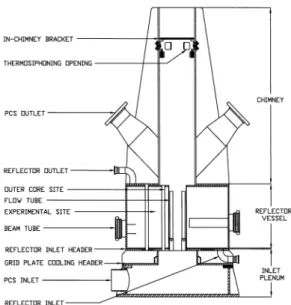
The reactor structure assembly is submerged in the reactor pool. The reactor structure assembly consists of five major components which are the inlet plenum, the lower grid plate, the flow tubes, the chimney, and the reflector tank at the bottom [1]. Figure 1 illustrates the main features of the HANARO reactor structure assembly. The inlet plenum supports the weight of the other reactor structure components and uniformly distributes cold inlet coolant to each flow channel. The lower grid plate holds the fuel assemblies and the in-core experimental facilities. The reflector tank containing a heavy water surrounds the reactor core and accommodates various horizontal and vertical experimental holes. In the outlet chimney in a hexagonal form, the heated core up-flow is mixed with the cold down-coming bypass flow and sucked out through a pair of angled outlet nozzles.
The compact reactor core contains 19 hexagonal and 12 cylindrical fuel assemblies. Each fuel assembly is separated and installed in a matching flow tube. A total of 31 removable flow tubes are arranged in a honeycomb lattice form in the inner core. The 8 fixed flow tubes embedded in the reflector tank are available for an additional fuel loading, which is called the outer core.
The primary cooling system circulates demineralized water to the reactor inlet plenum. The water from the inlet plenum then flows vertically up through the reactor fuel channels removing the heat produced by the fission in the
fuel. It exits from the core into the chimney, rises vertically to the two primary coolant pump suction pipe nozzles. There is one on each side of the chimney wall just above the core outlet. In the chimney the core coolant merges with the bypass flow coming down through the chimney opening from the reactor pool. About 10% of the total primary coolant, called the bypass flow, is directed to the bottom of the reactor pool instead of to the reactor inlet plenum. This water rises from the bottom of the pool around the outside of the reactor core structure, keeping the bottom of the reactor pool cooled.
Figure 1. Vertical cross sectional view of the HANARO reactor structure assembly.
2.2 CFD Model
For the CFD model, the flow regions are generated as two calculation domains with a real size. One is an IC region with the inlet plenum, lower grid plate and chimney, and the other is a FT region with the flow tubes. Because the heavy water circulates in the reflector tank as a different loop, the reflector tank model is excluded from this work. The total number of the elements is 2,300,000. With regards to the boundary conditions, the inlet plenum is defined as an INLET type patch with the inlet mass flow rate of 703 kg/s and each side of the outlet nozzles is
Transactions of the Korean Nuclear Society Autumn Meeting Busan, Korea, October 27-28, 2005
defined as an OUTLET type patch with the mass flow rate of 390 kg/s uniformly. The top of the chimney is defined as an OPENING type patch with a constant pressure condition. The wall of the inactive part of the chimney is defined as a WALL type patch with smooth and no slip conditions. The flow rate of the bypass flow (77 kg/s) was adjusted using boundary conditions. Numerical and physical parameters are set for the model.
For the CFD analysis of a turbulent flow, the standard k-ε model is used in this study. The convergence criteria are the mass residual reduction of 10-5. The physical timescale is 0.05sec. The maximum number of the steady state computation iterations is 200. In this simulation, the working fluid is water at 1atm. The physical properties are set as uniform and constant. The steady state computation using CFX-5 [2] is performed on a PC.
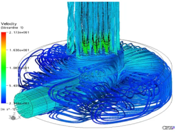
Figure 2. Velocity streamline of the inlet plenum.
Figure 3. Velocity plane at the top of the flow tubes.
The coolant from the inlet pipe penetrates deeply into the inlet plenum, separates along the sidewall and then moves upward forming a large vortex towards the core as shown in Figure 2. The large vortex can be a possible cause of wear in the structural materials of the fuel assemblies. Figure 3 illustrates the flow velocity at the top
of the flow tubes. A relative large velocity up-flow compared to other regions of the flow tubes is induced at the bottom of the flow tubes since the pool water from the inlet plenum is passed through each fuel channel rapidly due to the narrow flow gaps. The flow in the chimney is rather complicated as indicated in Figure 4. The upward core flow and downward chimney flow meet inside the chimney and then they are sucked out through the two outlet nozzles attached to the two sides of the chimney. Also, all the upward jet flow is suppressed inside the chimney.
Figure 4. Velocity streamline of the outlet nozzles and chimney.
3. Conclusions
In this study, the CFD analysis model using CFX-5 is established and used to perform the flow field in the HANARO. Results from the CFD analysis are suitable for evaluating the velocity fields and the flow patterns [3,4].
Acknowledgement
This study has been performed under the national R&D program supported by Korea Ministry of Science and Technology.
REFERENCES
[1] Korea Atomic Energy Research Institute, “HANARO: Safety Analysis Report”, KAERI/TR-710/96, 1996.
[2] AEA Technology, “CFX-5: User’s Manual”, Version 5.6, United Kingdom, 2003.
[3] Gee Y. Han, et al., “A Study on the HANARO Flow Fields”, 2004 Korean Nuclear Society Autumn Meeting, October 2004. [4] Heonil Kim and Gee Y. Han, “Flow Characteristics of the HANARO Reactor Pool”, IGORR-9, Australia, 2003.