Cold Test of 2 MW Transmitter for KSTAR ICH
J. G. Kwak, S. J. Wang, J. S. Yoon, Y. D. Bae and B. G. HongKorea Atomic Energy Research Institute [email protected]
1. Introduction
ICH(Ion Cyclotron Heating) is one of main heating systems at KSTAR(Korea Superconducting Tokamak for Advanced Research) and it has been known that it plays a role in the workhorse at plasma heating and current drive at tokamak. It heats the plasma at arbitrary radius depending on the toroidal magnetic field by varying rf frequency and drives the plasma current on axis or off-axis using FWCD(Fast Wave Current Drive)or MCCD(Mode Conversion Current Drive) methods.
The starting point for ICH system is the rf power source. It has been developed for many years as the application of airborne broadcasting and military purpose. Typically rf power level of one unit transmitter is 2 MW due to the restriction by the tube of the final amplifier stage. So this proven technology of the transmitter makes ICH consider as the big advantages compared with other wave heating methods at tokamak such as ECW(Electron Cyclotron Wave) and LHW(Lower Hybrid Wave).
In this work, the cold test for IPA and DA stages for KSTAR ICH transmitter is shown and the present status and detail results of the power test will be shown.
2. General description of rf power source
There have been developed many transmitters for applications of magnetically confined nuclear fusion. One of those is FMIT (Fusion Material Irradiation Test) transmitter which was developed about 20 yeas ago. The original design of FMIT is the fixed frequency and design of FMIT to another frequency was conceived by Mr. R. Clark.[1] Figure 1 shows the cross-section of the output cavity and the tuning elements. The inverted cup-shaped cylinder, T5 provides a substantial reduction in cavity length when it is operated down 30 MHz. The second one is Thomcast(nowadays its company name is changed as Thales) transmitter which has the wide frequency range from 30 to 120 MHz for 2 MW power.[2] However, their pulse length is limited within 10 sec. German company, Herfurth manufactured 2 MW transmitter for JET(Joint European Tokamak) but this company was disappeared. Recently, NIFS(National Institute of Fusion Science) developed the transmitter for ICH of LHD(Large Helical Device) and they succeeded to produce 1.6 MW for 5000 sec.[3]
Many transmitters take the form of the coaxial wave-guide structure originated from FM or VHF band transmitter and there is a little variation in the cavity design depending on the manufacturer. Nowadays, it is well known that the problem to produce 2 MW continuously is due to the dissipation limit of screen grid for tetrode tube not the cavity design. Typically there are two available candidates for the tetrode. One is Einmac 4CM2500KG and another is Thales TH628A diacrode.
There are several special features of ICH amplifier compared with broadcasting transmitter. One is their ability to work into changing antenna load. Because plasma condition varies very much such as ELM(Edge Localized Mode) case at tokamak, it affect the antenna impedance rapidly so that it is necessary not to exceed the dissipation limit of screen grid current of the tetrode at high reflected rf power. In addition, for tuning and conditioning of feeders and antennas, low power and pulse mode operation are needed.
Fig.1. Output cavity of FPA for FMIT.
3. rf source for KSTAR ICH Transactions of the Korean Nuclear Society Autumn Meeting
2 MW transmitter for KSTAR ICH has the frequency range from 30 to 60 MHz and 2 MW power is produced for the pulse length of 300 sec with the duty cycle of 15%. The pulse length can be controlled
with the rising time less than 100 μ sec by modulating low rf power level signal. The tetrode of final stage is Einmac 4CM2500KG tube. KAERI has developed the transmitter for KSTAR ICH system up to 300 kW. Finally it was determined that the first transmitter for KSTAR ICH is made by CEC(Continental Electronics Company) who is the manufacturer of FMIT transmitter. That contract was done at 2003 between KAERI and CEC and it will finish the final commissioning until 2006.
It is consists of three amplifier chains, intermediate amplifier(IPA), driver amplifier(DA) and final power amplifier(FPA). Its output power is 5, 100, 2000 kW respectively. It has the very similar structure with D-IIID’s FMIT transmitter except pulse length of rf power. The high voltage DC power supply for the plate is the conventional DC rectifier where AC voltage is step up by the transformer. The Crowbar unit using the ignitron is equipped for the interlock.
4. Cold test result
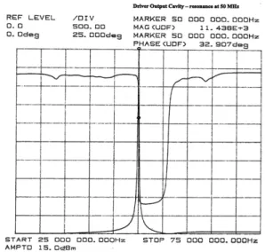
The cold probe test of IPA was done to investigate the rf characteristics of input and output cavity. Figure 2 shows S11 for output cavity of DA stage at 60 MHz. The test frequencies are 30, 33, 37, 50 and 60 MHz. It shows no parasitic oscillations and tuning can be done from 30 to 60 MHz.
Fig. 2. S11 of output cavity for DA stage at 60 MHz.
5. Summary and future works
The cold test for 2 MW transmitter is done for 30, 33, 37, 50 and 60 MHz. Present status and more detail results of power test will be shown in the conference.
REFERENCES
[1] N. Greenough et al., 17th IEEE/NPSS symposium fusion
engineering, vol. 1, p.452, 1997.
[2] J. Wyss et al., Course and workshop on applications on rf waves to tokamak plasmas, Italy, vol. 2, p.882, 1985.
[3] R. Kumazawa et al., Proc. 18th Symposium on Fusion Technology, vol.1, p. 617, 1996.