Superficial Dosimetry for Helical Tomotherapy
Song Yih Kim, M.D., Sei Hwan You, M.D., Taesoo Song, Ph.D., Yong Nam Kim, Ph.D., Ki Chang Keum, M.D., Jae Ho Cho, M.D., Chang Geol Lee, M.D. and Jinsil Seong, M.D.
Department of Radiation Oncology, Yonsei University College of Medicine, Seoul, Korea
Purpose: To investigate the feasibility of helical tomotherapy on a wide curved area of the skin, and its accuracy in calculating the absorbed dose in the superficial region.
Materials and Methods: Two types of treatment plans were made with the cylinder-shaped ‘cheese phantom’. In the first trial, 2 Gy was prescribed to a 1-cm depth from the surface. For the other trial, 2 Gy was prescribed to a 1-cm depth from the external side of the surface by 5 mm. The inner part of the phantom was completely blocked. To measure the surface dose and the depth dose profile, an EDR2 film was inserted into the phantom, while 6 TLD chips were attached to the surface.
Results: The film indicated that the surface dose of the former case was 118.7 cGy and the latter case was 130.9 cGy. The TLD chips indicated that the surface dose was higher than these, but it was due to the finite thickness of the TLD chips. In the former case, 95% of the prescribed dose was obtained at a 2.1 mm depth, while the prescribed does was at 2.2 mm in the latter case. The maximum dose was about 110% of the prescribed dose. As the depth became deeper, the dose decreased rapidly. Accordingly, at a 2-cm depth, the dose was 20 % of the prescribed dose.
Conclusion: Helical tomotherapy could be a useful application in the treatment of a wide area of the skin with curvature. However, for depths up to 2 mm, the planning system overestimated the superficial dose. For shallower targets, the use of a compensator such as a bolus is required.
Key Words: Helical tomotherapy, Tangential beam, Skin dose, Surface dose, Cheese phantom
Submitted February 23, 2009, accepted June 9, 2009
Reprint requests to Ki Chang Keum, Department of Radiation Oncology, Yonsei University College of Medicine, 134 Shinchon- dong, Seodaemoon-gu, Seoul 120-752, Korea
Tel: 02)2228-8095, Fax: 02)312-9033 E-mail: [email protected]
This study was supported by KFDA under Grant No. 06112-306. Introduction
Build-up phenomenon rather renders the treatment of super-ficial region difficult. In this case, an electron beam of which surface dose is higher and the penetration power to the deep region is less in comparison with a photon beam is used. However, for the case with a wide and curved treatment area, unavoidably more than one isocenter and more than one electron field should be used. In electron beam, the dose scattered to the lateral direction is relatively abundant, and thus the generation of high dose regions or low dose regions in the junction area is more serious in comparison with a
photon beam. If the body shape of patient is close to a cylindrical shape, electron arc therapy could be performed. But more non-cylindrical is the body shape to be treated, the dose homogeneity becomes lower.
On the other hand, photon beam therapy has been improved rapidly by the use of multileaf collimator (MLC). Intensity modulated radiation therapy (IMRT) becomes feasible by applying the MLC sequence, and recently, upon the intro-duction of helical tomotherapy (Tomotherapy, Inc., Madison, WI, USA), IMRT for the treatment of a wide range such as total body or total marrow becomes feasible.1) Such photon beam has the characteristic that if the direction of the incident beam were not normal but tangential to the surface area, the maximum dose appears in a more shallow depth. Because of such phenomenon, it has been reported that in the case of patients undergoing the head and neck radiation therapy, treated with IMRT technique that delivers the beam from several directions, higher doses were deposited on the skin than in the treatment with two opposite lateral directions.2)
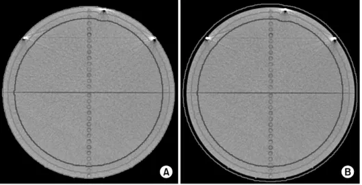
Fig. 1. Contouring in two trials (red
region is gross tumor volume, blue region is completely blocked re-gion) (A) air excluded (B) air in-cluded.
Various factors generate such results, and one of them is the head and neck mask used to fix the setup of patient. Even though the thickness of head and neck mask is thin, it makes shallower the shallowed maximum dose depth due to the tangential beam in IMRT.
Helical tomotherapy uses the binary dynamic MLC with the two types of option, on-off, and delivers the beam from 51 directions. Therefore, it can use tangential directions more effectively, and thus concerning skin radiation therapy, it is anticipated to give an effect comparable to electron beam therapy, although it’s nominal energy is 6 MV. Furthermore, it is expected to deposit a sufficient dose at skin without the application of a compensator for the build-up. On the other hand, the accuracy of dose calculation in the superficial region did not reach the reliable level until now. Indeed, it has been reported that the dose calculation applying the convolution/ superposition method overestimates the dose in the superficial region or at the junction area between two heterogeneous matters, where electron fluence is under the disequilibrium condition.3) In our study, the feasibility of treating a wide area of the skin by helical tomotherapy was examined. In addition, the accuracy of the dose calculation in the superficial region by helical tomotherapy was tested.
Materials and Methods
1. Contouring and planning
Helical tomotherapy provides a cheese phantom used for the delivery quality assurance (DQA). This phantom is cyrindrical
30 cm in diameter, which is similar to the size of the abdomen of patient. In the cases of real patients, the in-vivo dosimetry is extremely limited or impossible, and hence the cheese phantom for DQA was used in our study. Similar to other inverse planning systems, a radiation treatment plan of helical tomotherapy is generated after contouring the target and normal organs on CT images, and prescribing target dose and limitation dose for normal organs. To simulate patients undergoing skin region treatment, two artificial organs were drawn on the CT image of cheese phantom. One is a ring- shaped organ from the surface of the cheese phantom to 1 cm depth, and designated as GTV (gross tumor volume). The other is cylinder-shaped organ from 2 cm in depth, which was designated as a critical organ. In another trial, GTV-air was contoured from the external side of the surface by 5 mm to 1 cm depth, and a critical organ was drawn identically from 2 cm in depth (Fig. 1). After contouring, the fraction size 2 Gy was prescribed for GTV, and the internal critical organ was preset to be ‘completely blocked’, which means primary beam does not penetrate this region. In other words, dose deposited in this region is only from scattered beam. It simulates the hope that unnecessary dose should not be delivered into the inner part in the cases of patients undergoing the skin region treatment. The field width used at that time was 2.52 cm, the pitch was 0.3, and the modulation factor was 2.0, which are all default values. The pitch in helical tomotherapy is the translated distance of couch while the gantry rotates once, divided by the field size. In our case, while the gantry rotates once, couch was translated about 7.6 mm. The modulation factor is defined as the maximum leaf open time of any leaf
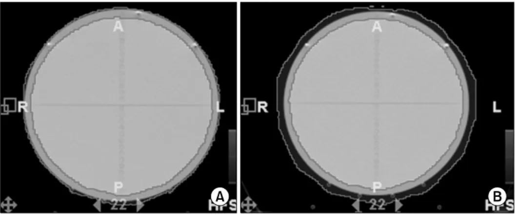
Fig. 2. The planning result of the
helical tomotherapy radiation treat-ment planning system on two types of trial. The red-colored region means more than the 95% of the pre-scribed dose 190 cGy is deposited. (A) Air excluded, (B) air included.
Fig. 3. An EDR2 film was inserted into cheese phantom, and 6
TLD chips were attached on the upper surface. divided by the average nonzero leaf open time, and is a
measure of the range of beam intensities within a single projection. As the modulation factor becomes larger, more variable intensity maps may be generated. After iteration was performed around 100 times, 95% of GTV volume got the prescribed dose as Fig. 2.
2. Calibration and measurement
To measure the surface dose and dose distribution within the cheese phantom, an EDR2 film (Kodak Co.) and 6 TLD chips with the size of 3.2×3.2×1.0 mm3 (Fimel, Co.) were used as shown in Fig. 3 Before using an EDR2 film and TLD chips, calibration for each is required. For an EDR2 film, a calibration films were made by 10 stages of 30 cGy from 0 cGy to 300 cGy and analyzed by the VIDAR dosimetrypro advantage scanner. For TLD chips, 5 times of irradiation were performed for calibration, and the average value of each chip was used as its reference. After the calibration, an EDR2 film was inserted to the cheese phantom on the coronal plane, and TLD chips were attached on the upper hemisphere of cheese phantom with approximately 20 degrees angular interval, and to prevent them from contaminating the EDR2 film, they were distanced from the film as much as possible. EDR2 films were fixed by a tape and marked on the projection of a red laser. To prevent undesired contamination of the film near the phantom surface area, it was marked in the area sufficiently distanced from the phantom surface.
3. Dose profile and the determination of phantom surface
After irradiation, it is required to accurately determine the location of the surface on the film data. If the surface were
marked to determine its location, the data around the surface would be contaminated, therefore, it is not a desirable method. The coordinate system in helical tomotherapy is that if a patient lies down in supine and head-first position, the superior/inferior direction is the Y axis, the anterior/posterior direction is the Z axis, and the right/left direction is the X axis. First, the dose profile along the line connecting two points marked on the X axis was obtained. Subsequently, assuming that the point with the maximum dose gradient on the profile is closely related to the surface location, two points with the maximum dose gradient were selected. The distance between these two points was 29.8 mm, which was almost equivalent to the diameter of phantom, 30 cm. We have defined points expanded from these two points outwardly by 1 mm as both surface positions. Or the surface position may be defined by the expansion based on both maximum values of the dose profile. However, because of the helical irradiation of
Table 1. Discrepancy in Surface Dose by Different Mea-suring Devices
Plan 1 Plan 2
Prescription dose 200 cGy 200 cGy
Prescription point 1 cm from surface 1 cm from surface +5 mm Measured surface dose (% of prescription dose)
EDR2 film 118.7 cGy (59.5%) 130.9 cGy (65.5%) TLD chip 163.2 cGy (81.6%) 174.0 cGy (87.0%)
Fig. 4. The result obtained from EDR2 films and TLD chips
after the irradiation.
Fig. 5. Comparison between the calculated dose profile and the measured one. (A) The result when the air excluded target, (B) the
result when the air included target.
tomotherapy, depth dose profile cannot be laterally symme-trical, and thus it isn’t an appropriate method. The fact that the distance between two points of the maximum dose gradient is less than 30 cm implies that the surface dose is less than the calculated one by radiation treatment planning (RTP) system. If a sufficient dose were deposited on the surface as predicted by RTP system, the distance between the maximum dose gradients should be more than 30 cm.
Results
1. Film results
The surface was defined based on the maximum dose
gradient position, and the depth dose profile of both sides was averaged. Fig. 4 shows a rapid increase of the dose in the surface region. In the case that GTV was defined from the surface, the surface dose was 118.7 cGy, and the case that GTV was defined by the expansion from the surface by 5 mm, it was 130.9 cGy. Since the prescribed dose was 200 cGy, it corresponds to 59.5% and 65.5% of the prescribed dose respectively (Table 1). In addition, to reach 95% of the prescribed dose, their depth has to be 2.1 mm and 2.2 mm respectively. This reveals that the calculated dose in the superficial region is quite different from the actual dose. Fig. 5 shows the comparison between the calculated dose and measured dose by an EDR2 film in the superficial region. The step-wise graph is the calculated one, and this shape is due to the finite size of calculation grid. As shown in the Fig. 5, there is a large discrepancy between calculated and measured
Fig. 6. Comparison between the depth dose profile of helical
tomotherapy and that of 6 MeV electron beam with SSD 100 setting.
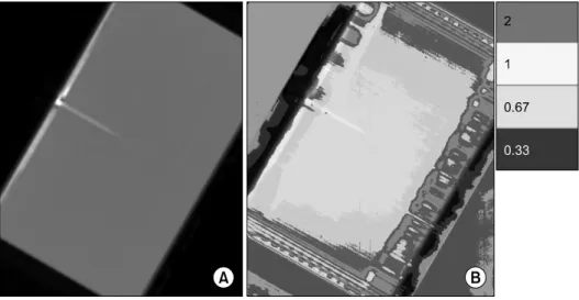
Fig. 7. The cross section of (A) the
cheese phantom and (B) Gamma values on it. The red color re-presents the area where the gamma value is higher than 2, the yellow color represents the area where the gamma value is between 1 and 2, the sky blue color represents the area where the gamma value is between 2/3 and 1, and blue color represents the area where the gam-ma value is between 1/3 and 2/3. The colorless represents the gamma value is lower than 1/3.
dose in the superficial region. A large discrepancy also exists in the air region outside the phantom, but air dose is clinically meaningless as well as the film data from the air region cannot be considered to be air dose. In both cases, the maximum dose appeared in 5∼6 mm depth. In the former case, the maximum dose was 207.5 cGy, and the latter case, 211.7 cGy, which correspond to about 110% of the prescribed dose. At 1 cm depth where the GTV area is ended, the former case was 189.4 cGy, the latter case was 185.2 cGy, which correspond to 95% of the prescribed dose or slightly less. Afterward, it began to decrease rapidly. At the depth of 2 cm from which ‘completely blocked’ was preset, the former case was 38.6 cGy, the latter case was 34.4 cGy, which are lower than 20% of the prescribed value. Fig. 6 shows the
comparison of the depth dose graphs obtained by tangential incidence of helical tomotherapy photon beam and by normal incidence of 6 MeV electron beam at SSD 100 setting. For comparison, the maximum value was normalized to be equi-valent each other. Although 6 MeV is generally the lowest nominal energy in electron beam of commercial linacs, the depth where the effective dose is delivered is deeper than that of helical tomotherapy. In the case of helical tomotherapy, about 18% of the prescribed dose was deposited in 2 cm depth. On the other hand, electron beam of 6 MeV still maintained 75%.
2. TLD results
TLD chips were used as a reference to measure the surface dose. Nonetheless, the result of TLC chip was substantially higher than the film result. In the case that the GTV was contoured from the surface, the TLD result was 163.2±24.9 cGy, and the case that GTV was expanded to the outside by 5 mm, it was 174.0±7.9 cGy. It respectively corresponds to 81.6% and 87% of the prescribed dose, and higher than film result by about 20% (Table 1). Such excessive result is thought to be from the finite thickness of TLD chips and their location. Kron T et al. extrapolated the surface dose by apply-ing commercial TLD chips with various thickness.4) Rapley P et al. measured the surface dose using TLD power to remove the thickness effect of TLD chips.5) This implies that the finite thickness of TLD chip may give rise to a substantial error on the surface dose. In addition, from the aspect that TLD is not located in the same level to the phantom surface but on the
phantom surface, its result cannot be considered to be the surface dose. Another characteristic in the TLD result is that the standard deviations in two trials are greatly different. This can be explained by the difference of the dose gradient at the surface. As shown in Fig. 4, the dose gradient of the case that GTV is contoured from the surface is larger than the case that GTV is contoured on the air expanded by 5 mm from the surface. Larger is the dose gradient, it is more sensitive to the set-up error. In that sense, it is reasonable that the former case shows a substantially larger standard deviation than the latter case.
3. Gamma test
To compare the dose measured on a film and the calculated one by helical tomotherapy RTP system, gamma test was performed. Gamma value is defined as follows.6,7)
2 2 ⎟⎟ ⎠ ⎞ ⎜⎜ ⎝ ⎛ + ⎟⎟ ⎠ ⎞ ⎜⎜ ⎝ ⎛ = Γ DD DTA C DD C DTA
DTA is the abbreviation of distance to agreement, and DD is dose difference. CDTA and CDD are criteria of DTA and DD.
In our study, they were 3 mm and 3% respectively. If the gamma value on a point is less than 1, the point is considered to pass the gamma test, and the point higher than 1 is considered to fail the test. This formula considers not only the inaccuracy of the calculation of dose but also the inaccuracy originated from setup errors. In other words, if a point with an identical dose exists within the area distanced by CDTA, and
the dose difference in the same location is not more than CDD,
gamma value may be less than 1. The left panel of Fig. 7 shows a cross section of a cheese phantom on which a film was put, and the irradiated surface region is its right upper side and left lower side. As observed in Fig. 7, the gamma value is more than 2 in the surface region, which means the calculated and measured dose are quite different. However at a certain depth from the surface, the gamma value decreased to less than 1, and the calculated value and the measured value are in good agreement. In a deep region where a primary beam didn’t enter but only a scattered beam entered, the gamma value increased again. It may come either from the inaccuracy of dose calculation or from the difficulty to measure low dose exactly with a film.
Discussion
From the film, the surface dose of the former case was 118.7 cGy and the latter case was 130.9 cGy. From TLD chips, surface dose was higher than these, but it was due to finite thickness of TLD chips. In the former case, 95% of the prescribed dose was obtained at 2.1 mm depth, and at 2.2 mm in the latter case. The maximum dose was about 110% of the prescribed dose. As the depth became deeper, the dose decreased rapidly, and at 2 cm depth, it became 20% of the prescribed dose. Although the helical tomotherapy delivers a megavoltage photon beam, it can use tangential directions effectively due to its multi-directional property, and thus generates the result comparable to electron beams when the superficial region is treated. In linac-based IMRT, intensity modulated beams are delivered generally from no more than 10 directions, and in the planning under the condition identical to our study, hot regions are generated regularly in the region where one field is overlapped with the adjacent fields. Com-pared with depth dose of normally incident, low energy elec-tron beam (6 MeV), that of tangentially incident, helical tomo-therapy photon beam decreases rapidly in more shallow depth. Of course, the depth dose profile of electron beam can be shifted upward by using a build-up compensator such as bolus. However, air gaps may be generated between the bolus and the skin of patient, which result in undesirable low dose on the skin due to rebuild-up phenomenon. Another supe-riority of helical tomotherapy to the electron beam is that intensity modulation is feasible. Even though a cylinder- shaped phantom was used in our study, the actual body shape of a patient is not cylindrical, but complex shape with various curvatures. In such cases, even if the arc therapy were used, the dose homogeneity within the target is decreased sub-stantially. However, helical tomotherapy can maintain good dose homogeneity by using intensity modulation. In fact, when total scalp irradiation is performed using helical tomotherapy, more homogeneous target dose and improved critical structure dose can be obtained than multiple matched electron fields, combination of electron and photon fields, and the linac-based IMRT.8) Nevertheless, in that study, the accurate measurement of the surface dose of helical tomotherapy and the assessment are not included.
The result of our measurement shows that the RTP system of helical tomotherapy overestimates the superficial dose up to 2 mm in depth. Therefore, for the cases that the region to be treated is within 2 mm from the skin, even if treated with helical tomotherapy, the application of a compensator for the build-up is required. Such overestimation of superficial dose has been already reported by several studies. Mutic S and Daniel A. Low have reported that irradiated a cylindrical phantom 16 cm in diameter by serial tomotherapy, a signi-ficant but shallow buildup region is present, and the depth reaches almost 3 mm.9) In addition, Dogan N and Glasgow GP have reported that in the cases irradiated by the obliquely incident, intensity modulated beam with 6 MV nominal energy, the calculated dose on the surface was overestimated by 25% than the value measured by a parallel plate chamber, and in 1 mm depth, it was overestimated by 5%.10) By our study, it was able to be confirmed that the phenomenon of the overestimation of superficial dose in such manners is also shown in helical tomotherapy.
In our study, a cheese phantom of which size is similar to the abdominal contour of humans was used. Nonetheless, the size of the arm or leg of a patient is substantially smaller than this. In addition, the abdominal contour of a patient cannot be a precisely cylinder shape. Therefore, for more precise studies, various sizes of phantoms or more realistic phantoms such as Rando phantom may be used. In the case of the phantom with irregular shape, it is thought that the local dose distributions may be different depending on the curvature of the external contour.
In addition, the relatively low dose phenomenon in superficial region may be suspected due to set-up errors. However, in helical tomotherapy, the setup is adjusted by taking Megavoltage CT (MVCT), and thus its set-up is most accurate in comparison with other machines. Even if some set-up errors were present, there may be set-up errors at the same level when a patient undergoes the treatment on the
skin. Therefore, our study provides useful information on skin or superficial region treatment by helical tomotherapy.
Conclusion
Helical tomography could be applied usefully to treat a wide area of the skin with curvature. However, up to 2 mm depth, the planning system overestimated superficial dose. For more shallow targets, to use a compensator such as bolus is required.
References
1. Hui SK, Kapatoes J, Fowler J, et al. Feasibility study of helical tomotherapy for total body or total marrow irradiation. Med Phys 2005;32:3214-3224
2. Lee N, Chuang C, Quivey JM, et al. Skin toxicity due to intensity radiotherapy for head-and-neck carcinoma. Int J Radiat Oncol Biol Phys 2002;53:630-637
3. Huang C, Chu T, Lin S, Lin J, Hsieh C. Accuracy of the convolution/superposition dose calculation algorithm at the condition of electron disequilibrium. Applied Radiation and Isotopes 2002;57:825-830
4. Kron T, Elliot A, Wong T, Showell G, Clubb B, Met-calfe P. X-ray surface dose measurements using TLD extrapolation. Med Phys 1993;20:703-711
5. Rapley P. Surface dose measurement using TLD powder extrapolation. Med Dosim 2006;31:209-215
6. Low DA, Harms WB, Mutic S, Purdy JA. A technique for the quantitative evaluation of dose distributions. Med Phys 1998;25:656-661
7. Thomas SD, Mackenzie M, Field GC, Syme AM, Fallone BG. Patient specific treatment verifications for helical tomotherapy treatment plans. Med Phys 2005;32:3793-3800 8. Orton N, Jaradat H, Welsh J, Tome W. Total scalp
irradiation using helical tomotherapy. Med Dosim 2005;30:162- 168
9. Mutic S, Low DA. Superficial doses from serial tomotherapy delivery. Med Phys 2000;27:163-165
10. Dogan N, Glasgow GP. Surface and build-up region dosimetry for obliquely incident intensity modulated radiotherapy 6 MV x rays. Med Phys 2003;30:3091-3096
국문초록