1.65 mm diameter forward-viewing confocal
endomicroscopic catheter using a flip-chip
bonded electrothermal MEMS fiber scanner
Y
EONG-H
YEONS
EO, K
YUNGMINH
WANG,
ANDK
I-H
UNJ
EONG*Department of Bio and Brain Engineering, Korea Advanced Institute of Science and Technology, 291 Daehak-ro, Yuseong-gu, Daejeon 34141, South Korea
Abstract: We report a 1.65 mm diameter forward-viewing confocal endomicroscopic
catheter using a flip-chip bonded electrothermal MEMS fiber scanner. Lissajous scanning was implemented by the electrothermal MEMS fiber scanner. The Lissajous scanned MEMS fiber scanner was precisely fabricated to facilitate flip-chip connection, and bonded with a printed circuit board. The scanner was successfully combined with a fiber-based confocal imaging system. A two-dimensional reflectance image of the metal pattern ‘OPTICS’ was successfully obtained with the scanner. The flip-chip bonded scanner minimizes electrical packaging dimensions. The inner diameter of the flip-chip bonded MEMS fiber scanner is 1.3 mm. The flip-chip bonded MEMS fiber scanner is fully packaged with a 1.65 mm diameter housing tube, 1 mm diameter GRIN lens, and a single mode optical fiber. The packaged confocal endomicroscopic catheter can provide a new breakthrough for diverse in-vivo endomicroscopic applications.
© 2018 Optical Society of America under the terms of the OSA Open Access Publishing Agreement
OCIS codes: (170.2150) Endoscopic imaging; (170.3880) Medical and biological imaging; (120.5800) Scanners.
References and links
1. T. Meinert, N. Weber, H. Zappe, and A. Seifert, “Varifocal MOEMS fiber scanner for confocal endomicroscopy,” Opt. Express 22(25), 31529–31544 (2014).
2. X. Duan, H. Li, J. Zhou, Q. Zhou, K. R. Oldham, and T. D. Wang, “Visualizing epithelial expression of EGFR in vivo with distal scanning side-viewing confocal endomicroscope,” Sci. Rep. 6(1), 37315 (2016).
3. P.-L. Hsiung, J. Hardy, S. Friedland, R. Soetikno, C. B. Du, A. P. Wu, P. Sahbaie, J. M. Crawford, A. W. Lowe, C. H. Contag, and T. D. Wang, “Detection of colonic dysplasia in vivo using a targeted heptapeptide and confocal microendoscopy,” Nat. Med. 14(4), 454–458 (2008).
4. C. Duan, X. Zhang, D. Wang, Z. Zhou, P. Liang, A. Pozzi, and H. Xie, “An endoscopic forward-viewing OCT imaging probe based on a two-axis scanning mems mirror,” in 2014 IEEE 11th International Symposium on Biomedical Imaging (ISBI) (2014), pp. 1397–1400.
5. W. Jung, D. T. McCormick, Y. C. Ahn, A. Sepehr, M. Brenner, B. Wong, N. C. Tien, and Z. Chen, “In vivo three-dimensional spectral domain endoscopic optical coherence tomography using a microelectromechanical system mirror,” Opt. Lett. 32(22), 3239–3241 (2007).
6. H. C. Park, Y. H. Seo, and K. H. Jeong, “Lissajous fiber scanning for forward viewing optical endomicroscopy using asymmetric stiffness modulation,” Opt. Express 22(5), 5818–5825 (2014).
7. H. C. Park, Y. H. Seo, K. Hwang, J. K. Lim, S. Z. Yoon, and K. H. Jeong, “Micromachined tethered silicon oscillator for an endomicroscopic Lissajous fiber scanner,” Opt. Lett. 39(23), 6675–6678 (2014).
8. B. J. Vakoc, D. Fukumura, R. K. Jain, and B. E. Bouma, “Cancer imaging by optical coherence tomography: preclinical progress and clinical potential,” Nat. Rev. Cancer 12(5), 363–368 (2012).
9. M. J. Gora, M. J. Suter, G. J. Tearney, and X. Li, “Endoscopic optical coherence tomography: technologies and clinical applications [Invited],” Biomed. Opt. Express 8(5), 2405–2444 (2017).
10. D. R. Rivera, C. M. Brown, D. G. Ouzounov, I. Pavlova, D. Kobat, W. W. Webb, and C. Xu, “Compact and flexible raster scanning multiphoton endoscope capable of imaging unstained tissue,” Proc. Natl. Acad. Sci. U.S.A. 108(43), 17598–17603 (2011).
11. W. Liang, G. Hall, B. Messerschmidt, M.-J. Li, and X. Li, “Nonlinear optical endomicroscopy for label-free functional histology in vivo,” Light: Sci. Appl. 6(11), e17082 (2017).
12. M. T. Myaing, D. J. MacDonald, and X. Li, “Fiber-optic scanning two-photon fluorescence endoscope,” Opt. Lett. 31(8), 1076–1078 (2006).
13. B. J. Reid, P. L. Blount, Z. Feng, and D. S. Levine, “Optimizing endoscopic biopsy detection of early cancers in Barrett’s high-grade dysplasia,” Am. J. Gastroenterol. 95(11), 3089–3096 (2000).
#315747 https://doi.org/10.1364/OE.26.004780 Journal © 2018 Received 15 Dec 2017; revised 29 Jan 2018; accepted 29 Jan 2018; published 14 Feb 2018
14. M. J. Gora, J. S. Sauk, R. W. Carruth, K. A. Gallagher, M. J. Suter, N. S. Nishioka, L. E. Kava, M. Rosenberg, B. E. Bouma, and G. J. Tearney, “Tethered capsule endomicroscopy enables less invasive imaging of gastrointestinal tract microstructure,” Nat. Med. 19(2), 238–240 (2013).
15. K. Hwang, Y.-H. Seo, and K.-H. Jeong, “Microscanners for optical endomicroscopic applications,” Micro. Nano Systems Lett. 5(1), 1 (2017).
16. E. J. Seibel and Q. Y. J. Smithwick, “Unique features of optical scanning, single fiber endoscopy,” Lasers Surg. Med. 30(3), 177–183 (2002).
17. X. Liu, M. J. Cobb, Y. Chen, M. B. Kimmey, and X. Li, “Rapid-scanning forward-imaging miniature endoscope for real-time optical coherence tomography,” Opt. Lett. 29(15), 1763–1765 (2004).
18. N. Zhang, T. H. Tsai, O. O. Ahsen, K. Liang, H. C. Lee, P. Xue, X. Li, and J. G. Fujimoto, “Compact piezoelectric transducer fiber scanning probe for optical coherence tomography,” Opt. Lett. 39(2), 186–188 (2014).
19. K. Hwang, Y.-H. Seo, J. Ahn, P. Kim, and K.-H. Jeong, “Frequency selection rule for high definition and high frame rate Lissajous scanning,” Sci. Rep. 7(1), 14075 (2017).
20. C. M. Lee, C. J. Engelbrecht, T. D. Soper, F. Helmchen, and E. J. Seibel, “Scanning fiber endoscopy with highly flexible, 1 mm catheterscopes for wide-field, full-color imaging,” J. Biophotonics 3(5-6), 385–407 (2010). 21. A. D. Aguirre, P. R. Hertz, Y. Chen, J. G. Fujimoto, W. Piyawattanametha, L. Fan, and M. C. Wu, “Two-axis
MEMS Scanning Catheter for Ultrahigh Resolution Three-dimensional and En Face Imaging,” Opt. Express
15(5), 2445–2453 (2007).
22. K. H. Kim, B. H. Park, G. N. Maguluri, T. W. Lee, F. J. Rogomentich, M. G. Bancu, B. E. Bouma, J. F. de Boer, and J. J. Bernstein, “Two-axis magnetically-driven MEMS scanning catheter for endoscopic high-speed optical coherence tomography,” Opt. Express 15(26), 18130–18140 (2007).
23. A. R. Cho, A. Han, S. Ju, H. Jeong, J.-H. Park, I. Kim, J.-U. Bu, and C.-H. Ji, “Electromagnetic biaxial microscanner with mechanical amplification at resonance,” Opt. Express 23(13), 16792–16802 (2015). 24. J. Sun, S. Guo, L. Wu, L. Liu, S. W. Choe, B. S. Sorg, and H. Xie, “3D in vivo optical coherence tomography
based on a low-voltage, large-scan-range 2D MEMS mirror,” Opt. Express 18(12), 12065–12075 (2010). 25. C. Duan, Q. Tanguy, A. Pozzi, and H. Xie, “Optical coherence tomography endoscopic probe based on a tilted
MEMS mirror,” Biomed. Opt. Express 7(9), 3345–3354 (2016).
26. X. Zhang, C. Duan, L. Liu, X. Li, and H. Xie, “A non-resonant fiber scanner based on an electrothermally-actuated MEMS stage,” Sens. Actuators A Phys. 233, 239–245 (2015).
27. X. J. Mu, W. Sun, H. H. Feng, A. B. Yu, K. W. S. Chen, C. Y. Fu, and M. Olivo, “MEMS micromirror integrated endoscopic probe for optical coherence tomography bioimaging,” Sens. Actuators A Phys. 168(1), 202–212 (2011).
28. Y.-H. Seo, K. Hwang, H.-C. Park, and K.-H. Jeong, “Electrothermal MEMS fiber scanner for optical endomicroscopy,” Opt. Express 24(4), 3903–3909 (2016).
1. Introduction
Optical endomicroscopy such as confocal [1–3], optical coherence tomography (OCT) [4–9], or multi-photon imaging [10–12] receive many attentions as a promising imaging tool for in-vivo diagnosis including optical biopsy [8, 13–15]. Miniaturized forward-viewing endomicroscopic catheters have been developed for endomicroscopic imaging applications and provide a new clinical trial through an accessory channel of a conventional endoscope. Integration of a high-resolution optical imaging into a small diameter catheter provides a non-invasive and real-time diagnosis of suspected lesions in a gastrointestinal track. Resonant fiber scanners are mainly applied for a forward-viewing catheter to provide high scanning amplitude with low operating voltage. In particular, quadratic piezoelectric (PZT) tube actuators are widely used in resonant fiber scanning owing to some technical merits, such as compact and robust packaging [6, 7, 16–20]. Nevertheless, PZT resonant fiber scanners still have some technical barriers for cost reduction.
Currently, micro-electro-mechanical system (MEMS) techniques have spurred a new breakthrough in miniaturized endomicroscopic catheters. Small size, high speed, and low-cost MEMS devices enable optical laser scanning within a restricted endoscopic accessory channel. MEMS scanners are mainly divided by the actuation methods: electrostatic [2, 5, 21], electromagnetic [22, 23], and electrothermal actuation [4, 24–27]. For in vivo applications, a driving voltage should be driven below the permissible voltage of 40
V
pp (IEC 60601-01). In this respect, the electrothermal actuation provides a large displacement under several tens of volts or less [9]. Electrothermal MEMS mirrors have been developed for side-viewing imaging [24, 27] and forward-viewing imaging [4]. For forward-viewingimaging using a MEMS mirror, the beam path should be folded and the size of the catheter is increased (around 5 mm outer diameter). MEMS Fiber scanners with the electrothermal actuation enable to overcome the size limitation of a forward-viewing MEMS mirror imaging. X. Y. Zhang et al. demonstrated a one-dimensional electrothermal fiber scanner by using an electrothermal stage [26], and Y. -H. Seo et al. recently demonstrated a two-dimensional Lissajous scanned electrothermal MEMS fiber scanner [28]. The Electrothermal MEMS fiber scanner provides an unfolded light path and offers ultrathin dimensions and low cost compared to the conventional quadratic PZT fiber scanner.
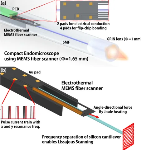
Fig. 1. (a) Schematic of a compact endomicroscopic catheter with a Lissajous scanned electrothermal MEMS fiber scanner. The MEMS fiber scanner is fabricated for flip-chip bonding, which minimized electrical packaging dimensions. Resulting in the scanner packaged with 1.65 mm diameter. (b) Working principle of the Lissajous scanned electrothermal MEMS fiber scanner. Thermal expansion of hot arm structures induced by Joule heating enables lateral scanning, and the bimorph structure between the silicon cantilever of the scanner and the mounted optical fiber induces vertical scanning. The asymmetric structure of the microactuator differentiates the effective stiffness in both directions, which enables Lissajous scanning.
Here we report a fully packaged 1.65 mm diameter forward-viewing confocal endomicroscopic catheter using a flip-chip bonded electrothermal MEMS fiber scanner. The miniaturization of the catheter was enabled by using a flip-chip bonding technique. The MEMS fiber scanner has six gold (Au) pads on the top silicon of the scanner. The six Au pads consist of two pads for electrothermal actuation and four pads for stable flip-chip bonding. The MEMS fiber scanner is integrated by a 0.2 mm thick printed circuit board (PCB) with six Au solder balls. Figure 1(a) shows the schematic of the compact packaged confocal endomicroscopic catheter using a flip-chip bonded MEMS fiber scanner. The MEMS fiber
scanner is fabricated for flip-chip bonding, which minimizes electrical packaging dimensions. Resulting in scanner packaged with 1.65 mm diameter. Figure 1(b) shows the working principle of the electrothermal MEMS fiber scanner. The lateral motion is derived by thermal expansion of hot arm structures due to Joule heating and the vertical motion is also induced by bimorph structures of the heated MEMS fiber scanner. The asymmetric structure of microactuator differentiates the effective stiffness of an optical fiber in both directions, which enables Lissajous scanning.
2. Device design and fabrication
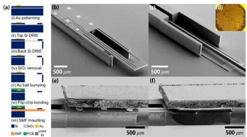
Fig. 2. (a) Microfabrication procedures of a flip-chip bonded MEMS fiber scanner. The microactuator is fabricated by using deep reactive ion etching (DRIE) on a heavily boron doped 6 inch SOI wafer (Top: 30 μm, Buried oxide (BOX): 2 μm, Bottom: 400 μm). After microactuator fabrication, the microactuator is released and flip-chip bonded with solder balls and a 0.2 mm thick printed circuit board (PCB). The flip-chip bonded scanner is assembled with optical fiber. (b) Top-view SEM image of the fabricated microactuator. The footprint dimension indicates 1 x 5 x 0.43 3
mm . (c) Bottom-view SEM image of the microactuator. The optical fiber is on the fiber groove of the microactuator. (d) An optical image of the fabricated 6 in. SOI wafer. (e) Side SEM image of the flip-chip bonded scanner. A 0.2 mm PCB is directly attached to the microactuator with solder balls. (f) Side-view SEM image of the underfilled scanner.
Figure. 2(a) shows the microfabrication procedures of a flip-chip bonded MEMS fiber scanner. The microactuator was fabricated by using deep reactive ion etching (DRIE) on a heavily boron doped 6-inch silicon-on-insulator (SOI) wafer (top Si: 30 μm, buried oxide (BOX): 2 μm, bottom Si: 400 μm in thickness). After microactuator fabrication, the microactuator was released and flip-chip bonded with 80 μm solder balls. The flip-chip bonded microactuator was assembled with a single mode optical fiber. Figure 2(b) shows a top-view SEM image of the microactuator. On the top side, 6 Au pads and double hot arm structures were well defined. The footprint dimension indicates 1 x 5 x 0.43 mm3. Figure 2(c)
shows a bottom-view SEM image of the microactuator. The single mode optical fiber (Thorlabs, SM-800) was assembled to the microactuator. Figure. 2(d) shows an optical image of the fabricated 6 in. SOI wafer. Microactuators were successfully fabricated at a wafer level. Figure 2(e) shows a side-view SEM image of the flip-chip mounted scanner. A 0.2 mm thick printed circuit board (PCB) was attached to the microactuator with six solder balls. After flip-chip bonding, a gap between the microactuator and the PCB was filled with underfill epoxy (PT-4100), as shown Fig. 2(f).
3. Lissajous scanning, confocal imaging, and catheter packaging
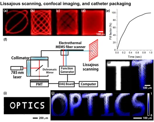
Fig. 3. (a)-(d) Lissajous patterns of the electrothermal MEMS fiber scanner. 378 ߤ݉ x 439 ߤ݉ field-of-view (F.O.V) Lissajous patterns were obtained within 16 Vpp operation voltage (scanning time: 1/125, 1/40, 1/20, 1/4 sec). (e) Calculated result of fill factor of Lissajous scanning pattern at 239 Hz, 207 Hz depending on scanning time (f) Schematic of the confocal endomicroscopic system. MEMS fiber scanner is combined with the fiber-based confocal system. (g) Optical image of reference metal target ‘T’ (line width is 80 μm). (h) Two-dimensional reflectance images of the metal pattern ‘T’ by using the confocal reflectance imaging system and the flip-chip bonded MEMS fiber scanner. (i) Optical image of reference metal pattern ‘OPTICS’. (j) Stitched confocal reflectance image of the metal pattern ‘OPTICS’.
Figures 3(a)-3(d) show Lissajous patterns of the electrothermal MEMS fiber scanner. 378 ߤ݉ x 439 ߤ݉ field-of-view (F.O.V) Lissajous patterns were obtained within 16 Vpp operation
voltage (scanning frequency: 239 Hz in x-axis, 207 Hz in y-axis, scanning time: 1/125, 1/40, 1/10, 1/4 sec). Figure 3(e) shows the calculated result for the fill factor in Lissajous scanning at 239 Hz, 207 Hz depending on the scanning time. The Lissajous pattern is filled in 86% for 0.5 sec and 100% for 1 sec. Figure 3(f) shows a schematic of the confocal reflectance endomicroscopic system. The MEMS fiber scanner was combined with the fiber-based confocal system (256 x 256 pixel resolution). Figure 3(g) is an optical image of the reference metal target ‘T’ (line width is 80 μm). A two-dimensional reflectance image of the metal pattern ‘T’ was obtained by using the confocal reflectance imaging system and the flip-chip bonded MEMS fiber scanner, as shown Fig. 3(h). In reflectance image, the phase does not fit correctly and there is some distortion, however, the image resolution can be improved through image processing including phase correction for the MEMS scanner or feedback control. Figure 3(i) is an optical image of reference metal pattern ‘OPTICS’. Figure 3(j) is a stitched confocal reflectance image of the metal pattern ‘OPTICS’. 785 nm laser is used for the confocal system, and the frame rate of the obtained image is 1 frame per second.
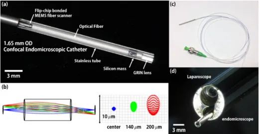
Fig. 4. (a) Optical image of a compact packaged endomicroscopic catheter. The inner diameter of the flip-chip bonded MEMS fiber scanner is only 1.3 mm and the endomicroscopic catheter was precisely assembled with a 1.65 mm diameter stainless tube and 1 mm diameter GRIN lens. Length of packaged catheter is 28 mm. (b) Ray tracing analysis with 1mm diameter GRIN lens (Edmund #64524, NA = 0.55). ± 200 μm scanning amplitude is used for ray tracing analysis. (Blue ray: center, green ray: ± 140 μm scanning amplitude, red ray: ± 200 μm scanning amplitude). RMS beam diameter is 0.27 μm at center, and 2.38 μm at 200 μm scanning amplitude. Working Distance at image side is 1 mm, and magnification is 1.1. (c) Optical image of the packaged endomicroscopic catheter. (d) Optical image of the packaged catheter assembled to laparoscopic functional channel.
Figure 4(a) shows the optical image of the fully packaged confocal endomicroscopic catheter. A 20 mm long optical fiber was attached to the flip-chip mounted MEMS fiber scanner, and a silicon mass was placed at the tip of the fiber, which increases scanning length of the scanner [6]. The flip-chip bonded scanner not only minimizes dimensions of electrical packaging, but also assists in the optical alignment of the fiber in catheter packaging. The dimensions of all packaging components, such as scanner width, solder ball size, and PCB thickness, have been precisely optimized to facilitate optical alignment. In the flip-chip bonded scanner, the distance from the center of the optical fiber to the edge of PCB is 0.65 mm. Therefore, when the scanner was inserted into the stainless housing tube (OD: 1.65 mm, ID: 1.3 mm), the fiber was centered in the housing tube without any additional component. The confocal endomicroscopic catheter was assembled with a 1.65 mm diameter stainless tube and a 1 mm diameter GRIN lens (Edmund #64524, NA = 0.55). For the precise fiber centering, a zig with a 125 μm groove in the center was prepared, the flip-chip bonded fiber scanner was inserted into a 1.65 mm diameter stainless tube, and the centering was adjusted back and forth by using a specialized zig and fixed with epoxy. The packaged catheter is 28 mm in length. Figure 4(b) shows a ray tracing analysis for ± 200 μm in scanning amplitude (Blue ray: center, green ray: ± 140 μm in scanning amplitude, and red ray: ± 200 μm in scanning amplitude). The RMS beam diameter is 0.27 μm at center and 2.38 μm at 200 μm in scanning amplitude, which provides 30,000 color pixels. The beam spot size can be decreased by using a customized objective lens. The working distance at the image side is 1 mm and the image magnification is 1.1x. Figures 4(c) and 4(d) show optical images of the packaged catheter and the packaged catheter assembled to a laparoscopic functional channel.
4. Summary
In summary, we have successfully demonstrated a fully packaged 1.65 mm diameter confocal endomicroscopic catheter using a flip-chip bonded electrothermal MEMS fiber scanner. The MEMS fiber scanner was precisely designed with six pads for a flip-chip connection, and 378
μm x 439 μm field-of-view (FOV) Lissajous patterns of the scanner were successfully obtained within the range of 16 V operation voltage. The flip-chip bonded MEMS fiber pp
scanner was successfully combined with the confocal imaging system, and a two-dimensional reflectance image was successfully obtained within 16 Vpp operation voltage. The inner diameter of the flip-chip bonded scanner is 1.3 mm with minimized flip-chip designed packaging. The confocal endomicroscopic catheter was assembled with a 1.65 mm diameter stainless housing tube and 1 mm diameter GRIN lens. This compact endomicroscopic MEMS catheter can provide many opportunities for in-vivo endomicroscopic applications.
Funding
Korea Health Industry Development Institute (KHIDI), funded by the Ministry of Health & Welfare, Republic of Korea (HI13C2181 and HI16C1111), the Ministry of Science, ICT and Future Planning (2016013061), and the Global Frontier Project (2011-0031848) of the Korea government.