Research Article
Effects of Focus Geometry on the Hard Rock-Cutting
Performance of an Abrasive Waterjet
Yohan Cha ,
1Tae-Min Oh,
2and Gye-Chun Cho
11Department of Civil and Environmental Engineering, Korea Advanced Institute of Science and Technology (KAIST),
Daejeon 34141, Republic of Korea
2Department of Civil Engineering, Pusan National University, Pusan 46241, Republic of Korea Correspondence should be addressed to Gye-Chun Cho; [email protected]
Received 26 August 2019; Accepted 17 December 2019; Published 30 January 2020 Academic Editor: Constantin Chalioris
Copyright © 2020 Yohan Cha et al. This is an open access article distributed under the Creative Commons Attribution License, which permits unrestricted use, distribution, and reproduction in any medium, provided the original work is properly cited. Abrasive waterjets are being increasingly used in civil engineering for rock and concrete cutting, particularly for the demolition or repair of old structures. The energy of an abrasive waterjet is primarily provided by the accelerated abrasive. The momentum transfer during mixing and acceleration determines the abrasive velocity, which affects the cutting performance. Meanwhile, the geometry of the focus at which mixing occurs influences the momentum transfer efficiency. In this study, the effects of the focus geometry on the optimum abrasive flow rate (AFR) and momentum transfer characteristics in hard rock cutting were investigated. Experiments were conducted using granite specimens to test the AFR under different focus geometry conditions such as diameter and length. The results show that the focus geometry significantly affects the maximum cutting depth and optimum AFR. The maximum cutting energy was analyzed based on the cutting efficiency of a single abrasive particle. In addition, the momentum transfer parameter (MTP) was evaluated from the empirical relationship between the maximum energy and the cutting depth for granitic rocks. Accordingly, a model for estimating the MTP based on the AFR was developed. It is expected that the results of this study can be employed for the optimization of waterjet rock cutting.
1. Introduction
The increasing population has caused an increase in con-struction and maintenance of old structures in urban areas. Various methods such as blasting, rock splitting, and power breaker are used [1–3], but the use of these methods in urban areas causes noise, vibration, and environmental pollution. Therefore, various researches in fields such as cutting, dentation, and demolition have been conducted with in-creasing interest and necessity for cutting and breaking of rock and concrete [4–6]. On the contrary, waterjets using high-pressure water and abrasives are employed for the industrial cutting and cleaning of a variety of materials. The advantages of waterjets include the adjustability of the cutting and removal rates, low noise and low vibration, and environmental friendliness because only water and abrasives are required. In particular, this approach is beneficial due to the possibility of removing concrete without damaging the
inner reinforcements, thereby increasing its usability in civil engineering [7–10]. Thus, the waterjet is well suited for urban construction and maintenance of old structures.
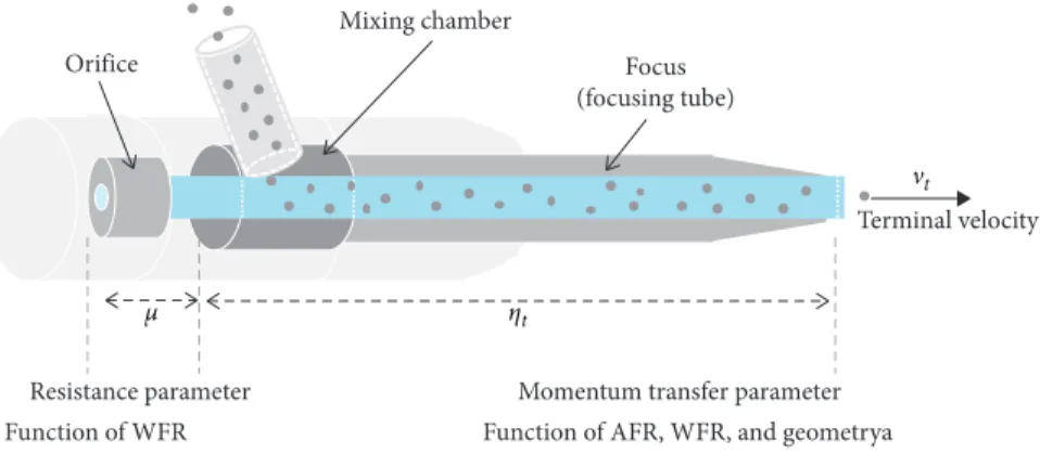
In the waterjet technique, the high-pressure water produced by a water pump assembly passes through an orifice and becomes a high-velocity water stream. The subsequently injected abrasives are mixed and accelerated by the high-velocity water stream (Figure 1). These accelerated abrasives provide the majority of the cutting energy of the abrasive waterjet [11, 12]. The focus keeps the particles in a jet as a mixed beam, thereby reducing the exposed cutting area and spreading angle. Therefore, geometric optimization of the focus increases the energy transfer and enhances the cutting efficiency [13]. Accordingly, the inner space of the focus affects the cutting energy [14, 15]. A certain focus length is required for the abrasives to be accelerated suffi-ciently, but friction between the abrasives and the wall occurs inside the focus. This friction slows down the Volume 2020, Article ID 1650914, 13 pages
abrasives, reducing the cutting depth [16, 17]. Another key parameter controlling the cutting depth is the abrasive flow rate (AFR) [16, 18]. Above a certain AFR, which depends on the waterjet system configuration, the abrasives cannot be maximally accelerated; thus, the cutting performance de-creases due to particle collisions [13, 19]. Therefore, an optimum AFR exists for a certain waterjet system, including the orifice and focus geometry.
Previous experimental studies have shown that abrasive waterjet cutting results vary depending on the deformation behavior of the target, such as its ductility or brittleness [20, 21]. Because the impact frequency or single-particle energy has different effects depending on the deformation behavior of the target [16, 22, 23], the properties of the target material affect the optimum AFR according to the focus geometry. Cutting experiments have been conducted to investigate the effects of the effective diameter of the orifice and focus by measuring the cutting depth or roughness [20, 21, 24–26]. For ductile materials such as steel, the effects of the AFR and focus diameter on the cutting depth have been investigated [17, 27], while for brittle materials such as sandstone, the focus diameter has been used as a variable but the effects of the water flow rate and AFR have not been considered [28, 29]. In addition, the effects of the focus length on the input mass of the abrasive have been measured for ductile materials such as AlMiSi0.5 [17] and those on the standoff distance for a suspension jet have been evaluated [30]. Since the AFR is related to the abrasive waterjet cost, AFR optimization has been widely investigated for economic reasons to avoid the excessive use of abrasives. Unlike in a suspension jet system, the cutting depth of an injection waterjet system increases to the optimum AFR and then decreases [16, 19, 31–33].
On the contrary, the abrasive mixing and acceleration efficiency is a function of all parameters related to mixing and acceleration, such as the pressure, AFR, orifice diameter, and focus geometry [16] (Figure 1). The momentum transfer parameter (MTP), which represents the mixing and accel-eration efficiency, is very important because it directly affects the cutting energy. This parameter can be obtained by measuring the ratio between the velocities of the mixture and water stream, or their forces [34, 35]. The MTP due to wall friction and mixing losses strongly affects the cutting per-formance, and previous experimental results have shown that
this parameter increases with increasing water pressure [20, 34, 36]. Other studies have indicated that the MTP, which is due to the interaction of the abrasive and water with the walls of the mixing chamber and focus, depends on the focus geometry [37–40], but there is a lack of research describing the characteristics of the MTP. By estimating the cutting energy according to the AFR, the MTP can be evaluated.
According to the literature review, very limited attempts have been made to study the effects of the focus geometry on the optimum AFR considering the water flow rate in hard rock cutting. As various applications of abrasive waterjets are expected in civil engineering, economic utilization of abra-sives must be achieved, which requires evaluating the effects of the focus geometry on the optimum AFR during rock cutting. Thus, the objectives of the present study were to evaluate the effects of the focus geometry on the optimum AFR and the momentum transfer characteristics in hard rock cutting. For these purposes, experiments were conducted with different focuses considering the water flow rate. Based on the experimental results, the characteristics of the optimum AFR and momentum transfer were investigated. The results can be used to develop an adjustable focus and to achieve economic utilization of abrasives for geotechnical purposes.
2. Theoretical Background
The accelerated abrasive serves as the main energy source in rock cutting, according to its velocity and mass [11, 12, 41]. In order to evaluate the rock-cutting characteristics, it is necessary to examine the process generating the kinetic energy of the abrasive and its influencing parameters.
In a waterjet system, after the high-pressure water produced by the pump passes through the orifice, it is converted into a high-velocity water stream. In this case, Bernoulli’s law gives the energy of the high-pressure water and high-velocity water stream:
pw,p ρw +v 2 w,p 2 + gh � pw,o ρw +v 2 w,o 2 + gh, (1)
where pw,p is the water pressure at the pump, ρw is the
density of water, g is the gravitational acceleration, h is the hydraulic head, vw,pis the velocity of water at the pump, pw,o
is the pressure of the water stream at the orifice, and vw,ois
Orifice
Mixing chamber
Focus (focusing tube)
Resistance parameter Momentum transfer parameter
Function of WFR Function of AFR, WFR, and geometrya
Terminal velocity
ηt
μ
νt
the velocity of the water stream at the orifice. When pw,pand
vw,o are much greater than pw,o and vw,p, respectively, the
water pressure at the pump is directly related to the velocity of water at the orifice:
pw,p ρw �v 2 w,o 2 . (2)
As water passes the orifice, the water flow resistance occurs in the form of wall friction, fluid-flow disturbance, and the compressibility of water [16]. When the resistance parameter (μ) is applied (Figure 1), the initial fluid velocity, which is the velocity of the water stream, can be expressed as
vw,o�μ ����� 2pw,p ρw . (3)
The high-velocity water stream accelerates the abrasives. The general flow of abrasive acceleration and the factors affecting the efficiency are illustrated in Figure 1. The energy of the water stream is converted into the kinetic energy of the abrasive-water mixture:
_
mwvw,o� _mwvw+ _mava � m_w+ _mavt, (4) where _mwis the flow rate of water, _mais the flow rate of the abrasive, and vt is the terminal velocity, at which the
ve-locities of the abrasive and water are equal. In effect, the terminal velocity can be calculated by considering the MTP (ηt), depending on the mixing and acceleration efficiency:
vt�ηt
vw,o
1 + _ma/ _mw. (5)
The MTP generally varies from 0.57 to 0.85 [42]. The effective kinetic energy (Eet) for rock cutting can be obtained from the mass and velocity of the accelerated abrasive: Eet�1 2· _ma· v 2 t � 1 2· _ma· ηt vw,o 1 + _ma/ _mw 2 . (6)
The AFR and geometry of the mixing space affect the mixing efficiency; therefore, the cutting characteristics are expected to be affected by the MTP. Figure 2 shows the effective kinetic energy at different MTPs (i.e., ηt�0.57 and
0.81). At the same abrasive flow rate, a 32% higher MTP results in a 45% higher effective kinetic energy. Meanwhile, the decrease in the MTP with the increasing AFR (i.e., ηt�0.81 ⟶ 0.57) changes the optimum AFR, which shows
the maximum cutting depth. Therefore, the change in the optimum AFR can be expected to change the MTP.
The energy distribution shape of abrasives follows the normal distribution ([43, 44]), and the maximum energy (Emax) centered at the effective jet radius is obtained by the standard deviation of the energy distribution (σ) considering the probability density [41]:
Emax� Eet
2πσ2. (7)
The effective jet radius is where erosion occurs due to the effective energy. It is determined by the standoff
distance (SOD), jet diffusion angle (θ), and focus diameter (df) at which diffusion begins. In the standard jet
dis-tribution, according to the transformed random variable (Za), the standard deviation of the energy distribution
becomes
σ �SOD · tan θ + df/2
Za . (8)
For the effective jet radius at a probability of 99%, the random variable (Z0.005) is 2.576.
The kinetic energy of a particle is assumed to be absorbed completely by particle impacts [45–47]. Based on maximum energy and cutting depth (D) results, a unique empirical curve was previously proposed for granite cutting [41]:
D �α Emax
1J
β
, (9)
where α � 3.5 ± 1.4 and β � 0.62 ± 0.1. Substituting equations (6) and (7) into equation (9), the MTP (ηt) becomes
ηt� ���������� 4πσ2 _ ma D α 1/β 1 + _ma/ _mw vw,0 . (10)
The MTP can be estimated using the relationship between the maximum energy according to the abrasive waterjet operation conditions and the experimentally obtained cutting depth. Since the MTP is a function of the AFR, the power equation relationship between the MTP (ηt) and the AFR
( _ma) is assumed to be
ηt� x _ma y
, (11)
where x and y are empirically determined.
Meanwhile, the optimum AFR can be expressed as a power function, including the AFR and cutting depth [33]:
D � kRm_ma, (12)
where kRis the reaction velocity coefficient, which can be
determined experimentally. The power exponent, the re-action order (m), decreases from 1 to 0 depending on the AFR. It is 0 at the maximum cutting depth; at the optimum AFR, it becomes less than 0 and yields cutting depth results with a bell shape according to the AFR.
0 20 40 60 80 100 120 140 160 180 200 0 0.5 1 1.5 2 2.5
Effective kinetic energy,
Eet (J)
ηt = 0.57
Optimum abrasive flow rate ηt = 0.85
ηt = 0.85 0.57
Abrasive flow rate, m·α (g/s)
Figure 2: Effects of the momentum transfer parameter on the abrasive kinetic energy.
3. Rock-Cutting Experimental Program
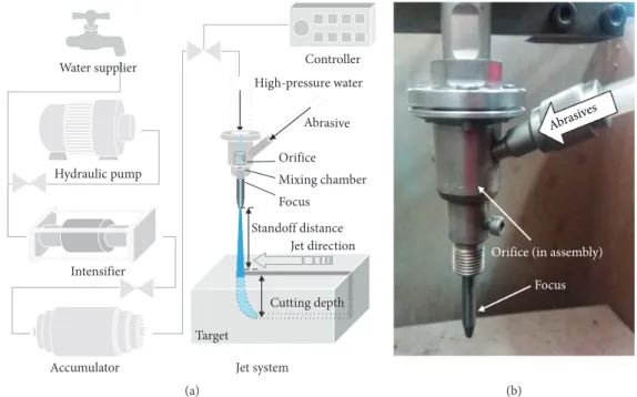
Figure 3 shows a schematic diagram of the test setup and the waterjet head assembly. An intensifier pump capable of generating up to 420 MPa of high-pressure water at a water flow rate of 6 l/m was used. The device moving the waterjet head, at a constant rate, was attached to the experimental chamber.
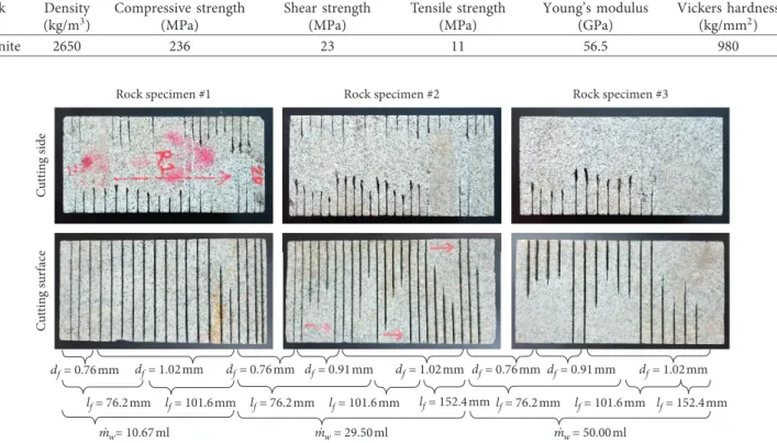
In this experiment, in order to evaluate effects of the focus geometry, focuses with three inner diameters (0.76, 0.91, and 1.02 mm) and three lengths (76.2, 101.6, and 152.4 mm) were used together with three orifices (0.15, 0.54, and 0.33 mm; Figure 4) for different water flow rate con-ditions (10.67, 29.50, and 50.00 ml/s). The pressure of the waterjet was 320 MPa, and the standoff distance between the target surface and the focus tip was 10 mm. The waterjet head with the focus was moved in one direction during rock cutting at a speed of 8.4 mm/s to prevent low incidence angles due to striation formation [48]. The AFR was changed from 3.3 to 29 g/s to estimate the optimum value. The ex-perimental cases are summarized in Table 1.
Garnet (Fe2O3Al2(SiO4)3), the most common abrasive (Table 2), was used for granitic rock cutting. The high scratch resistance of garnet due to its hardness has contributed to making it the most popular abrasive. The mean size of the abrasive particles was 80 mesh (0.18 mm; Figure 5), to op-timize the ratio between the abrasive-particle diameter and the focus diameter (df(op) �3dp[49]), so that the prepared
garnet could be used for various inner diameters of the focus. The intact target rock was granite, which is classified as a very strong rock [50]. Granite is one of the most frequently encountered rocks at construction sites, making it suitable for various waterjet applications in civil engineering. The physical properties of the rock were estimated according to the test methods suggested by the American Society for Testing and Materials and International Society for Rock Mechanics [51, 52]. The uniaxial compressive strength of the rock specimen was 236 MPa, its tensile strength was 11 MPa, and its Young’s modulus was 56.5 GPa. The details of granite are provided in Table 3.
4. Rock-Cutting Results
Cutting results of an abrasive waterjet with different focus geometry and water flow rates for single traverse are shown in Figure 6. Abrasive flow rates were varied from 3 to 6 types for each experimental condition. The characteristics depending on the focus geometry, the abrasive-water flow rate, the optimum abrasive flow rate, and the mixing effi-ciency were analyzed for rock cutting.
4.1. Influence of Focus Diameter. Figure 7 shows the effect of the focus diameter on the cutting depth. In all of the ex-perimental cases, the larger the focus diameter, the higher the cutting depth at the same AFR. At a water flow rate of 10.67 ml/s (Figure 7(a)), the maximum cutting depth was observed at the minimum AFR. At a water flow rate of 29.5 ml/s (Figure 7(b)), the greater the focus diameter, the
higher the optimum AFR and the greater the maximum cutting depth. These characteristics were the same at the higher water flow rate of 50 ml/s, where the cutting depth and optimum AFR were observed to increase at all focus diameters (Figure 7(c)). As the optimum AFR changes with the focus diameter, the change in the MTP (Figure 2) by increasing the AFR can be expected. On the contrary, under the same focus conditions, increasing the water flow rate increased the optimum AFR and maximum cutting depth (Figure 7(d)). The optimal focus diameter was previously supposed to be 3-4 times the orifice diameter [17], but it was 3.09–6.8 times in this experiment.
4.2. Influence of Focus Length. Figure 8 shows the effect of the focus length on the cutting depth. The cutting depth de-creased with the increasing focus length in this setup. At a flow rate of 10.67 ml/s (Figure 8(a)), the maximum cutting depth was observed at the minimum AFR, and the cutting depth decreased with the increasing abrasive input. At the higher water flow rates of 29.5 ml/s and 50 ml/s (Figures 8(b) and 8(c)), the maximum cutting depth was measured at the minimum abrasive flow rate at the longest focus length. On the contrary, increases in the cutting depth and optimal AFR were observed at focus lengths of 76.2 and 101.6 mm. With the increasing focus length, the mixing and acceleration efficiency decreases and the cutting depth also decreases. Increasing the water flow rate increased the optimum AFR and maximum cutting depth, indicating that the total energy increased with the increasing water flow rate. The decrease in the cutting depth with the increasing AFR is dramatic when the water flow rate is low (Figure 8(d)). These results were interpreted as illustrating the effects of the change in the MTP (ηt).
4.3. Maximum Cutting Depth. If the cutting depth shows both an increase and a decrease, the reaction order (m) from equation (12) indicates a value of 1 to less than zero, and the maximum cutting depth appears at zero. In all of the ex-periments with lower cutting depth conditions such as small focus diameter, excessive length, and low water flow rate (Figures 7(a), 8(b), and 8(d)), the reaction order (m) for the optimum AFR was always observed to be less than zero (equation (12)). For these operation conditions, more eco-nomical rock cutting can be achieved by replacing the focus or adjusting the water flow rate by changing the orifice diameter.
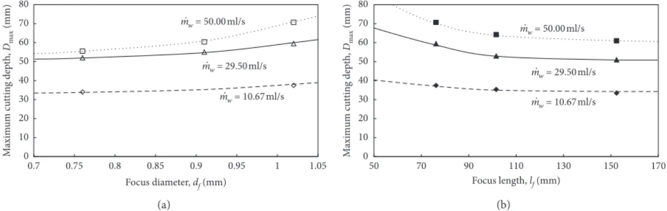
Figure 9 shows the maximum cutting depth as functions of the focus diameter and length, demonstrating that the higher the water flow rate, the greater the maximum cutting depth. These results indicate that the maximum cutting depth varies sensitively with both the focus diameter and the focus length at higher water flow rates. In addition, the water flow rate induces more variation of the maximum cutting depth with the focus length than the focus diameter. The influence of the focus diameter is greater at higher water flow rates (Figure 9(a)), while that of the focus length is the opposite (Figure 9(b)).
Jet direction Target High-pressure water Mixing chamber Orifice Focus Standoff distance Cutting depth Abrasive Water supplier Hydraulic pump Intensifier
Accumulator Jet system
Controller
(a)
Orifice (in assembly) Focus
Abrasives
(b)
Figure 3: Experimental setup for the abrasive waterjet rock cutting: (a) rock-cutting test setup; (b) cutting head assembly.
df= 0.91 and lf= 76.2mm df= 1.02 and lf= 76.2mm df= 1.02 and lf= 101.6mm df= 1.02 and lf= 152.4mm ϕ 0.33mm ϕ 0.254mm ϕ 0.15mm df= 0.76 and lf= 76.2mm
Figure 4: Various types of orifices and focuses.
Table 1: Experimental study cases and details.
Water pressure (MPa) 320
Standoff distance (mm) 10
Traverse speed (mm/s) 8.4
Effects of water and abrasive flow rates
Orifice diameter (mm) 0.15 0.254 0.33
Water flow rate (mL/s) 10.67 29.50 50.00
Abrasive flow rate (g/s) 3.3–14.2 4.0–24.0 4.4–29.0
Effect of focus diameter (focus length 76.2 mm) Focus diameter (mm)
0.76 0.76 0.76
— 0.91 0.91
1.02 1.02 1.02
Effect of focus length (focus diameter 1.02 mm) Focus length (mm)
76.2 76.2 76.2
101.6 101.6 101.6
5. Discussion
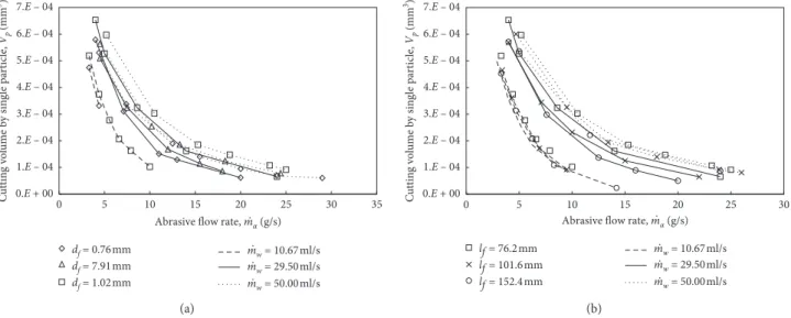
5.1. Optimum AFR Principle. The experimental results show that even with the same water and abrasive acceleration conditions, the energy of the abrasive is affected by the focus geometry, which changes the cutting performance. To evaluate the effects of the focus geometry on a single abrasive particle, the cutting performance was analyzed by dividing the total cutting volume by the number of abrasive particles
injected. Figure 10 shows the cutting volume due to a single particle. As the number of abrasive particles increased, the cutting efficiency of the single abrasive particle was greatly decreased. The increase in the cutting volume of a single abrasive particle with the increasing focus diameter can be explained by an increase in the terminal velocity of the abrasive-water slurry (equation (5)) as the mixing efficiency increases (Figure 10(a)). Thus, sufficient space is required for efficient mixing of the abrasive. However, the longer the
Rock specimen #1 Rock specimen #2 Rock specimen #3
m·w = 29.50 ml m·w = 50.00 ml df = 0.76mm df = 1.02mm lf = 76.2 mm lf = 101.6 mm df = 0.76mm df = 0.91mm lf = 76.2 mm lf = 101.6 mm df = 1.02mm lf = 152.4 mm df = 0.76mm df = 0.91mm lf = 76.2 mm lf = 101.6 mm df = 1.02mm lf = 152.4 mm C u tt in g sur face C u tt in g side m·w= 10.67 ml
Figure 6: Cutting results of an abrasive waterjet with different focus geometry and water flow rates. Table 3: Properties of the target rock.
Rock type Density (kg/m3) Compressive strength (MPa) Shear strength (MPa) Tensile strength (MPa) Young’s modulus (GPa) Vickers hardness (kg/mm2) Granite 2650 236 23 11 56.5 980 (a) 0 20 40 60 80 100 0.01 0.1 1 Percentage passing Particle size (mm) 40 60 80 100 Distribution rate (%) Particle size (mm) 0 20 0.85 0.6 0.425 0.25 0.18 0.15 0.075 0.053 (b)
Figure 5: Abrasive for the experiment: (a) India garnet; (b) particle size distribution. Table 2: Properties of the abrasive.
Abrasive type Component Density (kg/m3) Mean particle size (mm) Vickers hardness (kg/mm2)
focus, the smaller the cutting volume of the single abrasive particle (Figure 10(b)). A sufficient focus length is required for acceleration, but the cutting performance is reduced due to the decrease in mixing efficiency at excessively long focus lengths. The reduction of the mixing efficiency indicates an increase in the amount of collisions between the focus inner surface and the abrasive particles, as well as an increase in the amount of collisions between abrasive particles due to ex-cessively long mixing time depending on the water flow rate. Figure 11 shows the total cutting volume by accumulation of single-particle cutting volume according to the AFR for a water flow rate of 50.00 ml/s with a focus diameter of 1.02 mm and focus length of 76.2 mm. These results demonstrate that increasing the impact frequency leads to the highest total kinetic energy and optimum AFR even though the single-particle cutting rate decreases. At an AFR greater than the optimum AFR, the total cutting volume decreases due to the reduction of the effective kinetic energy (equation (6)) caused by a decrease in the single-particle cutting volume, which depends on the terminal velocity and momentum transfer (equation (5)). The optimum AFR and maximum cutting depth are attributable to the increase in total energy with the increasing impact frequency, and the total energy decrease
can be interpreted as a reduction of the single-particle cutting volume. In conclusion, when the reaction order (m) in equation (12) is greater than zero (optimum AFR), the cutting depth is dominated by the impact frequency, while it is dominated by the decrease in impact energy due to terminal velocity reduction when m is less than zero.
5.2. MTP Changes with Focus Geometry and Abrasive Flow Rate. The decrease in cutting depth due to the increase in the AFR varies with the focus geometry and the water flow rate (Figures 7 and 8). The results of this experiment reveal the relationship between the cutting depth and the mo-mentum transfer. Since the accelerated abrasive provides the majority of the energy of an abrasive waterjet, the cutting depth is proportional to the kinetic energy of the abrasive [53–55]. Therefore, changes in the kinetic energy can be predicted based on the cutting depth [41]. The reason that the kinetic energy changes is that the terminal velocity (equation (5)) is reduced due to the MTP along with the AFR. Thus, the MTP can be expected to change with the AFR based on the maximum energy-cutting depth relationship (equation (10)).
0 2 4 6 8 10 12
Abrasive flow rate, m·α (g/s) 80
Cutting depth,
D
(mm)
m·w = 10.67ml/s
Optimum abrasive flow rate 0 10 20 30 40 50 60 70 df = 0.76mm df = 1.02mm (a) m·w = 29.50ml/s 0 5 10 15 20 25 30
Abrasive flow rate, m·α (g/s)
Cutting depth, D (mm) 0 10 20 30 40 50 60 70 80
Optimum abrasive flow rate df = 0.76mm
df = 0.91mm df = 1.02mm
(b)
0 5 10 15 20 25 30
Abrasive flow rate, m·α (g/s) m·w = 50.00ml/s Cutting depth, D (mm) 0 10 20 30 40 50 60 70 80 df = 0.91mm df = 1.02mm
Optimum abrasive flow rate df = 0.76mm
(c)
0 5 10 15 20 25 30
Abrasive flow rate, m·α (g/s) m·w = 10.67ml/s m·w = 29.50ml/s m·w = 50.00ml/s Cutting depth, D (mm)
Optimum abrasive flow rate 0 10 20 30 40 50 60 70 80 (d)
Figure 7: Effects of the focus diameter on the cutting depth at a constant lf�76.2 mm with water flow rates of (a) 10.67 ml/s, (b) 27.50 ml/s,
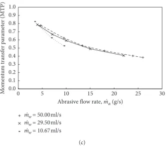
Figure 12 shows the MTP according to the AFR with different focus diameters and a focus length of 76.2 mm (Figure 12(a)), as well as with different focus lengths and a focus diameter of 1.02 mm (Figure 12(b)). As the focus diameter increases or focus length decreases, the MTP in-creases slightly, in direct relation to the cutting depth result
(Figures 7 and 8). The water flow rate significantly affects the cutting depth (Figures 7(d) and 8(d)), but the abrasive-water mass ratio ( _ma/ _mw) does not affect the MTP because it determines the velocity of the abrasive and is reflected by the unique empirical values of the curve in equation (9) (e.g., α and β). M axim um c u tt in g dep th, Dmax (mm) 0 10 20 30 40 50 60 70 80 0.75 0.8 0.85 0.9 0.95 1 1.05 0.7 Focus diameter, df (mm) m·w = 50.00ml/s m·w = 29.50ml/s m·w = 10.67ml/s (a)
Maximum cutting depth,
Dmax (mm) 0 10 20 30 40 50 60 70 80 70 90 110 130 150 170 50 Focus length, lf (mm) m·w = 50.00ml/s m·w = 29.50ml/s m·w = 10.67ml/s (b)
Figure 9: Relation between the focus geometry and the maximum cutting depth at an SOD of 10 mm: (a) focus diameter; (b) focus length.
Cutting depth,
D
(mm)
0 2 4 6 8 10 12 14 16
Abrasive flow rate, m·α (g/s) 0 10 20 30 40 50 60 70 80 m·w = 10.67ml/s lf = 101.6mm lf = 76.2mm
Optimum abrasive flow rate lf = 152.4mm (a) 0 5 10 15 20 25 30 Cutting depth, D (mm)
Abrasive flow rate, m·α (g/s) 0 10 20 30 40 50 60 70 80 m·w = 29.50 ml/s
Optimum abrasive flow rate lf = 152.4mm lf = 101.6mm lf = 76.2mm (b) Cutting depth, D (mm) 0 5 10 15 20 25 30
Abrasive flow rate, m·α (g/s) 0 10 20 30 40 50 60 70 80 m·w = 50.00ml/s lf = 101.6mm lf = 76.2mm
Optimum abrasive flow rate lf = 152.4mm (c) Cutting depth, D (mm) 0 5 10 15 20 25 30
Abrasive flow rate, m·α (g/s) 0 10 20 30 40 50 60 70 80
Optimum abrasive flow rate
m·w = 50.00ml/s
m·w = 29.50ml/s m·w = 10.67ml/s
(d)
Figure 8: Effects of the focus length on the cutting depth at a constant df�1.02 mm with water flow rates of (a) 10.67 ml/s, (b) 27.50 ml/s,
0 20 40 60 80 100 120 140 160 0 5 10 15 20 25 30 Impact frequency-dominant section
Terminal velocity and energy decrease-dominant section Line f or num ber of pa rticles Impac t frequenc y incr eased 0.E + 00 1.E – 04 2.E – 04 3.E – 04 4.E – 04 5.E – 04 6.E – 04 7.E – 04 C u tt in g v o lume b y sin gle pa rt ic le , V p (mm 3) T o ta l c u tt in g v o lu me , V (mm 3/mm)
Abrasive flow rate, mα (g/s) Total cutting volume
Cutting volume by single particle
·
Figure 11: Accumulation of single-particle cutting volume at df�1.02 mm, lf�76.2 mm, and _mw�50.00 ml/s. 0.E + 00 1.E – 04 2.E – 04 3.E – 04 4.E – 04 5.E – 04 6.E – 04 7.E – 04 0 5 10 15 20 25 30 35 C ut tin g v ol ume b y sin gle pa rt ic le , Vp (mm 3)
Abrasive flow rate, mα (g/s)
df = 0.76mm df = 7.91mm df = 1.02mm · mw = 10.67ml/s mw = 29.50ml/s mw = 50.00ml/s · · · (a) 0 5 10 15 20 25 . . . 30 0.E + 00 1.E – 04 2.E – 04 3.E – 04 4.E – 04 5.E – 04 6.E – 04 7.E – 04 C ut tin g v ol ume b y sin gle pa rt ic le , Vp (mm 3) mw = 10.67ml/s mw = 29.50ml/s mw = 50.00ml/s lf = 76.2mm lf = 101.6mm lf = 152.4mm
Abrasive flow rate, m·α (g/s)
(b)
Figure 10: Cutting volume due to single-particle impact: effects of (a) focus diameter and (b) focus length.
M omen tum tra nsf er pa ra met er (MTP) 0.0 0.1 0.2 0.3 0.4 0.5 0.6 0.7 0.8 0.9 1.0 0 5 10 15 20 25 30
Abrasive flow rate, mα (g/s)
df = 0.76mm df = 0.91mm df = 1.02mm m·w = 29.50ml/s · (a) M o men tum tra n sf er pa ra met er (MTP) 0.0 0.1 0.2 0.3 0.4 0.5 0.6 0.7 0.8 0.9 1.0 0 5 10 15 20 25 30
Abrasive flow rate, mα (g/s) mw = 29.50 ml/s lf = 152.4mm lf = 101.6mm lf = 76.2mm · · (b) Figure 12: Continued.
One of the objectives of this study was to provide a relationship between the MTP and the AFR for hard rock cutting. Figure 13 shows the MTP as a function of the AFR, which was calculated using equation (10). The MTP-AFR characteristics are correlated with x � 1.1 ± 0.05 and y � − 0.19 ± 0.08 in equation (11). When the AFR is low, the change in the MTP is great, and the MTP gradually con-verges to 0.5 as the AFR increases. MTP reduction with the increasing AFR was also found in a previous experimental study, in which a very small MTP (ηt�0.5) was associated
with an extremely high AFR ( _ma�65 g/s) [56]. Even though
it is difficult to measure the MTP quantitatively, this ap-proach enables the MTP (ηt) to be estimated qualitatively
according to the AFR ( _ma).
6. Conclusion
The purposes of this study were to evaluate the effects of the focus geometry on the hard rock-cutting depth with the optimum abrasive flow rate (AFR), as well as the charac-teristics of the momentum transfer parameter (MTP). Rock-cutting experiments were conducted considering the water flow rate with different focus diameters and lengths. The cutting depth was measured according to the AFR under each set of conditions, and the characteristics of the opti-mum AFR were reviewed by indicating the relation between the impact frequency and the cutting volume of a single abrasive particle. In addition, the MTP was estimated based on the AFR. The experimental results and considerations can be summarized as follows:
(i) The greater the focus diameter, the greater the optimum AFR and the maximum rock-cutting depth. Thus, sufficient space is required for abrasive mixing and acceleration.
(ii) The rock-cutting depth decreases when the focus length is too long, as does the optimum AFR. An excessive acceleration distance therefore reduces the
momentum transfer because of the interference between the abrasive particles, as well as the abrasive friction with the inner surface of the focus. (iii) The optimum AFR is a function of the impact
frequency, which increases with the increasing AFR, and the single-abrasive particle cutting rate, which decreases due to the reduction of the MTP and the terminal velocity.
(iv) In granite cutting, the MTP was estimated from the empirical relationship between the maximum en-ergy and the cutting depth using a power equation. This model can be employed to estimate the MTP based on the AFR.
(v) The change in the MTP is not significantly affected by the water flow rate, slightly affected by the focus geometry, and mainly affected by the AFR. When the AFR is low, the MTP changes considerably and converges to 0.5 gradually as the AFR increases. As a limitation of this study, the ranges of the orifice diameter and focus geometry were restricted. The waterjet system accessories utilized were in the ranges for common
0 0.1 0.2 0.3 0.4 0.5 0.6 0.7 0.8 0.9 1 0.00 5.00 10.00 15.00 20.00 25.00 30.00 x = 1.1 ± 0.05 y = –0.19 ± 0.08 R2 > 0.95 ηt (MTP) = x(m·α)y (m·α > 3.3 (g/s)) M o men tum tra n sf er pa ra met er (MTP)
Abrasive flow rate, m·α (g/s)
Figure 13: Momentum transfer parameter as a function of the abrasive flow rate in granite cutting.
M o men tum tra n sf er pa ra met er (MTP) 0 5 10 15 20 25 30 0.0 0.1 0.2 0.3 0.4 0.5 0.6 0.7 0.8 0.9 1.0
Abrasive flow rate, mα (g/s) m·w = 50.00 ml/s
m·w = 29.50 ml/s m·w = 10.67 ml/s
·
(c)
Figure 12: Momentum transfer parameter with different focus geometry parameters: (a) effects of focus diameter at lf�76.2 mm; (b)
products, and rock-cutting rates outside the experimental range were expected. Through further study of the struc-tural characteristics of the system, it will be possible to perform abrasive waterjet rock-cutting predictions to en-hance the waterjet efficiency. The results of this study can be employed to estimate the rock-cutting performance and to achieve economical operation by avoiding excessive abrasive use.
Nomenclature
D: Cutting depth (mm)
Dmax: Maximum cutting depth (mm) df: Diameter of the focus (mm)
df(op): Optimum diameter of the focus (mm) dp: Diameter of the abrasive particle (mm) Eet: Effective kinetic energy (J)
Emax: Maximum energy in effective kinetic energy distribution (J)
g: Gravitational acceleration (m/s2)
h: Hydraulic head (m)
kR: Reaction velocity coefficient lf: Length of the focus (mm)
lf(op): Optimum length of the focus (mm) _
ma: Abrasive flow rate (g/s) _
mw: Water flow rate (mL/s)
Pw,o: Pressure of water in the orifice section (Pa) Pw,p: Pressure of water in the pump section (Pa)
V: Total cutting volume (mm3/mm) Vp: Cutting volume by single particle (mm3) va: Velocity of the abrasive particle (m/s) vt: Terminal velocity (m/s)
vw: Velocity of the fluid (m/s)
vw,o: Velocity of water in the orifice section (m/s)
vw,p: Velocity of water in the pump section (m/s) Za: Transformed random variable
θ: Jet diffusion angle
ηt: Momentum transfer parameter
μ: Resistance parameter
ρw: Fluid density (g/mm3)
σ: Standard deviation of waterjet kinetic energy (mm) AFR: Abrasive flow rate (g/s)
MTP: Momentum transfer parameter SOD: Standoff distance (mm).
Data Availability
The experimental data (figures and tables) used to support the findings of this study are included within the article.
Conflicts of Interest
The authors declare that they have no conflicts of interest.
Acknowledgments
This work was supported by the National Research Foun-dation of Korea (NRF) grant funded by the Korean gov-ernment (MSIT) (no. 2017R1A5A1014883).
References
[1] T. Zhao, W. Liu, and Z. Ye, “Effects of water inrush from tunnel excavation face on the deformation and mechanical performance of shield tunnel segment joints,” Advances in Civil Engineering, vol. 2017, Article ID 5913640, 18 pages, 2017.
[2] Y. Shu, P. Shao, C. Dong, Z. Cao, and X. Yi, “Influence of rock strength on the propagation of slotted cartridge blasting-in-duced directional cracks,” Advances in Civil Engineering, vol. 2019, Article ID 5752189, 12 pages, 2019.
[3] H. Munoz, A. Taheri, and E. Chanda, “Rock cutting char-acteristics on soft-to-hard rocks under different cutter in-clinations,” International Journal of Rock Mechanics and Mining Sciences, vol. 87, no. 87, pp. 85–89, 2016.
[4] W. Wang, M. Wang, and X. Liu, “Study on mechanical features of Brazilian splitting fatigue tests of salt rock,” Ad-vances in Civil Engineering, vol. 2016, Article ID 5436240, 10 pages, 2016.
[5] W. Liu, X. Qian, T. Li, Y. Zhou, and X. Zhu, “Investigation of the tool-rock interaction using Drucker-Prager failure crite-rion,” Journal of Petroleum Science and Engineering, vol. 173, pp. 269–278, 2019.
[6] X. Zhu, W. Liu, and X. He, “The investigation of rock in-dentation simulation based on discrete element method,” KSCE Journal of Civil Engineering, vol. 21, no. 4, pp. 1201– 1212, 2017.
[7] Y. Lu, J. Tang, Z. Ge, B. Xia, and Y. Liu, “Hard rock drilling technique with abrasive water jet assistance,” International Journal of Rock Mechanics and Mining Sciences, vol. 60, pp. 47–56, 2013.
[8] K.-I. Song, T.-M. Oh, and G.-C. Cho, “Precutting of tunnel perimeter for reducing blasting-induced vibration and damaged zone-numerical analysis,” KSCE Journal of Civil Engineering, vol. 18, no. 4, pp. 1165–1175, 2014.
[9] J.-G. Kim, J.-J. Song, S. S. Han, and C.-I. Lee, “Slotting of concrete and rock using an abrasive suspension waterjet system,” KSCE Journal of Civil Engineering, vol. 16, no. 4, pp. 571–578, 2012.
[10] Y. Cha, A. Tae-Zin, and G.-C. Cho, “The state of abrasive waterjet technologies for construction in Korea,” in Proceedings of the 6th International Young Geotechnical Engineers Con-ference, pp. 86-87, Seoul, Republic of Korea, September 2017. [11] A. Momber, “The kinetic energy of wear particles generated by abrasive–water-jet erosion,” Journal of Materials Processing Technology, vol. 83, no. 1–3, pp. 121–126, 1998.
[12] P. Roth, H. Looser, K. Heiniger, and S. B¨uhler, “Determi-nation of abrasive particle velocity using laser-induced fluorescence and particle tracking methods in abrasive water jets,” in Proceedings of the 2005 WJTA Conference and Ex-position, pp. 21–23, Houston, TX, USA, August 2005. [13] D. Andersson and K. Ingvarsson, “Design of experiment and
evaluation of abrasive waterjet cutting in titanium alloy sheet,” Master thesis, Department of Materials and Manufacturing Technology, Chalmers University of Tech-nology, Gothenburg, Sweden, 2015.
[14] S. Hloch, M. Gombar, and J. Valicek, “Analysis of abrasive waterjet factors influencing the cast aluminium surface roughness,” International Journal of Precision Technology, vol. 1, no. 1, pp. 1–10, 2007.
[15] M. K. Babu and O. K. Chetty, “A study on the use of single mesh size abrasives in abrasive waterjet machining,” The International Journal of Advanced Manufacturing Technology, vol. 29, no. 5-6, pp. 532–540, 2006.
[16] A. W. K. Momber, Principles of Abrasive Water Jet Machining, Springer, London, UK, 1997.
[17] H. Blickwedel, Erzeugung und Wirkung von Hochdruck-Abrasivstrahlen, VDI-Verlag, D¨usseldorf, Germany, 1990. [18] M. C. Shaw, Principles of Abrasive Processing, Oxford
Uni-versity Press Inc., New York, NY, USA, 1996.
[19] T.-M. Oh and G.-C. Cho, “Characterization of effective pa-rameters in abrasive waterjet rock cutting,” Rock Mechanics and Rock Engineering, vol. 47, no. 2, pp. 745–756, 2013. [20] M. Hashish, “Optimization factors in abrasive-waterjet
ma-chining,” Journal of Manufacturing Science and Engineering, vol. 113, no. 1, pp. 29–37, 1991.
[21] E. J. Chalmers, “Effect of parameter selection on abrasive waterjet performance,” in Proceedings of the 6th American Water Jet Conference, pp. 345–254, Houston, TX, USA, August 1991.
[22] C. Huang, H. Zhu, X. Lu, Q. Li, and C. Che, “Transition mechanism from brittle fracture to ductile shear when ma-chining brittle materials with an abrasive waterjet,” Inter-national Journal of Precision Engineering and Manufacturing, vol. 9, no. 2, pp. 11–17, 2008.
[23] T. Nguyen and J. Wang, “A review on the erosion mechanisms in abrasive waterjet micromachining of brittle materials,” International Journal of Extreme Manufacturing, vol. 1, no. 1, Article ID 012006, 2019.
[24] J. J. R. Jegaraj and N. R. Babu, “A soft computing approach for controlling the quality of cut with abrasive waterjet cutting system experiencing orifice and focusing tube wear,” Journal of Materials Processing Technology, vol. 185, no. 1–3, pp. 217–227, 2007.
[25] P. J. S. W. C. J. Munoz, “Comprehensive evaluation of abrasive waterjet cut surface quality,” in Proceedings of the 6th American Waterjet Conference, pp. 139–161, Houston, TX, USA, August 1991.
[26] H. L. N. S. Guo and G. Meier, “Surface structure and kerf geometry in abrasive waterjet cutting: formation and opti-mization,” in Proceedings of the 7th American Waterjet Conference, pp. 1–14, Seattle, WA, USA, August 1993. [27] J. Kechagias, G. Petropoulos, and N. Vaxevanidis,
“Appli-cation of Taguchi design for quality characterization of abrasive water jet machining of TRIP sheet steels,” The In-ternational Journal of Advanced Manufacturing Technology, vol. 62, no. 5–8, pp. 635–643, 2012.
[28] M. Hebling, Grundlagenuntersuchungen tiber das Schneiden von Gestein mit abrasiven Hochstdruckwasserstrahlen, Ph.D thesis, RWTH Aachen University, Aachen, Germany, 1988. [29] M. K. Babu and O. V. Krishnaiah, “Studies on abrasive
waterjet machining of black granite through design of ex-periments,” Experimental Techniques, vol. 27, no. 5, pp. 49–54, 2003.
[30] A. Laurinat, H. Louis, and G. Tebbing, “Premixed abrasive water jets-the influence of important parameters,” in Jet Cutting Technology, pp. 577–591, Springer, Letchworth, UK, 1992.
[31] C. Brandt, “Abrasive suspension jets at working pressures up to 200 MPa,” in Proceedings of the 12th International Con-ference Jet Cutting Technology, pp. 489–507, Rouen, France, October 1994.
[32] H. Oweinah, “Leistungssteigerung des Hoch-druckwasserstrahlschneidens durch Zugabe von Zusatz-stoffen,” Dissertation, Technische Universit¨at Darmstadt, Darmstadt, Germany, 1990.
[33] A. Momber, “A generalized abrasive water jet cutting model,” in Proceedings of the 8th American Water Jet Conference, pp. 359–376, Houston, TX, USA, August 1995.
[34] A. W. K. Momber, “Energy dissipative processes in high speed water solid particle erosion,” Proceedings of the ASME Heat Transfer and Fluids Engineering Divisions, vol. 321, pp. 555– 564, 1995.
[35] A. W. Momber, “Energy transfer during the mixing of air and solid particles into a high speed waterjet- an impact force study,” Experimental Thermal and Fluid Science, vol. 25, no. 1-2, pp. 31–41, 2001.
[36] M. Hashish, “Pressure effects in abrasive-waterjet (AWJ) machining,” Journal of Engineering Materials and Technology, vol. 111, no. 3, pp. 221–228, 1989.
[37] H. Li, R. Wang, D. Yang, W. Zhou, and L. Li, “Determination of rotary cutting depth on steel pipes with the abrasive water jet technique,” Proceedings of the Institution of Mechanical Engineers, Part C: Journal of Mechanical Engineering Science, vol. 225, no. 7, pp. 1626–1637, 2011.
[38] A. M. Hoogstrate, T. Susuzlu, and B. Karpuschewski, “High performance cutting with abrasive waterjets beyond 400 MPa,” CIRP Annals, vol. 55, no. 1, pp. 339–342, 2006. [39] M. Ramulu, “Dynamic photoelastic investigation on the
mechanics of waterjet and abrasive waterjet machining,” Optics and Lasers in Engineering, vol. 19, no. 1–3, pp. 43–65, 1993.
[40] L. Cui, L. An, and W. Gong, “Effects of process parameters on the comminution capability of high pressure water jet mill,” International Journal of Mineral Processing, vol. 81, no. 2, pp. 113–121, 2006.
[41] T.-M. Oh and G.-C. Cho, “Rock cutting depth model based on kinetic energy of abrasive waterjet,” Rock Mechanics and Rock Engineering, vol. 49, no. 3, pp. 1059–1072, 2015.
[42] U. Himmelreich, Fluiddynamische Modelluntersuchungen an Wasserabrasivstrahlen, VDI-Verlag, Dusseldorf, Germany, 1993.
[43] S. J. Leach, G. L. Walker, A. V. Smith, I. W. Farmer, and G. Taylor, “Some aspects of rock cutting by high speed water jets,” Philosophical Transactions for the Royal Society of London. Series A, Mathematical and Physical Sciences, vol. 260, no. 1110, pp. 295–310, 1966.
[44] A. Henning and E. Westkamper, “Modelling of wear mech-anisms at the abrasive waterjet cutting front,” in Proceedings of the 2003 WJTA American Waterjet Conference, WJTA, Houston, TX, USA, August 2003.
[45] S. M. Wiederhorn and B. J. Hockey, “Effect of material pa-rameters on the erosion resistance of brittle materials,” Journal of Materials Science, vol. 18, no. 3, pp. 766–780, 1983. [46] S. M. Wiederhorn and B. R. Lawn, “Strength degradation of glass impacted with sharp particles: I, annealed surfaces,” Journal of the American Ceramic Society, vol. 62, no. 1-2, pp. 66–70, 1979.
[47] J. Zeng and T. J. Kim, “An erosion model of polycrystalline ceramics in abrasive waterjet cutting,” Wear, vol. 193, no. 2, pp. 207–217, 1996.
[48] G. Fowler, I. R. Pashby, and P. H. Shipway, “The effect of particle hardness and shape when abrasive water jet milling titanium alloy Ti6Al4V,” Wear, vol. 266, no. 7-8, pp. 613–620, 2009.
[49] M. Mozurkiwicz, L. Fincuan, and R. Ferguson, Investigation of Abrasive Cutting Head Internal Parameters, P. A. Woods, Ed., ISJCT Papers, Ottawa, Canada, 1988.
[50] E. T. Brown, Rock Characterization testing and Monitoring, Pergamon Press, New York, NY, USA, 1981.
[51] A. Standard, “Standard test method for compressive strength and elastic moduli of intact rock core specimens under varying states of stress and temperatures,” ASTM Interna-tional, vol. 10, pp. D7012–D7014, 2014.
[52] R. Altindag and A. G¨uney, “ISRM suggested method for determining the Shore hardness value for rock,” International Journal of Rock Mechanics and Mining Sciences, vol. 43, no. 1, pp. 19–22, 2006.
[53] I. Finnie, “Erosion of surfaces by solid particles,” Wear, vol. 3, no. 2, pp. 87–103, 1960.
[54] A. W. Momber, “Stress–strain relation for water-driven particle erosion of quasi-brittle materials,” Theoretical and Applied Fracture Mechanics, vol. 35, no. 1, pp. 19–37, 2001. [55] P. Jankovic, T. Igic, and D. Nikodijevic, “Process parameters
effect on material removal mechanism and cut quality of abrasive water jet machining,” Theoretical and Applied Me-chanics, vol. 40, no. 2, pp. 277–291, 2013.
[56] T. Isobe, “Distribution of abrasive particles in abrasive water jet and acceleration mechanism,” in Proceedings of the 9th International Symposium on Jet Cutting Technology, pp. 217–238, Sendai, Japan, October 1988.