66-1 / J. –H. Park
• IMID 2009 DIGEST
Abstract
Integral imaging provides an efficient way to display three-dimensional images with high degree of viewing freedom. Pickup process of integral imaging can also be utilized to acquire three-dimensional contents for displays. This paper introduces basic principle and recent progress of integral imaging technique.
1. Principle of integral imaging
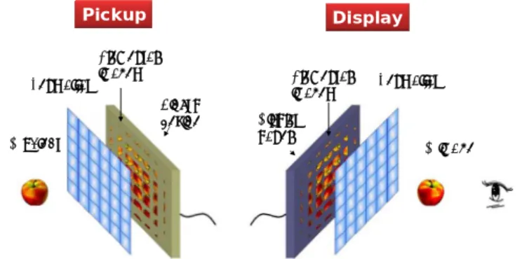
Integral imaging is a technique to capture and reconstruct three-dimensional(3D) images.1-3 Capture process, which is also called pickup process, uses a lens array and an image sensor like charge-coupled device(CCD). In operation, each elemental lens of the lens array forms an image of the 3D object. This image is called elemental image. All elemental images are slightly different each other due to the lateral position difference of the corresponding elemental lenses. The image sensor records all elemental images at the same time. The recorded elemental images can be directly used for the display process for presenting 3D images optically, or can be processed digitally to visualize 3D structure of the object. In the display process, the elemental images are displayed on the flat panel display and imaged by the lens array. Elemental lenses of the lens array relay the corresponding elemental images to the object space such that the 3D images are formed at the location of the originally captured object. Figure 1 shows the schematic of integral imaging. The principle of the integral imaging can also be explained using the concept of ray space or plenoptic optics. Since the integral imaging can acquire 3D information of the object by single capturing process without any scanning, it can be used for efficient 3D contents generation method. The 3D images displayed by integral imaging can exhibit not only horizontal parallax but also vertical parallax. Moreover, integral imaging does not require any pre-defined viewpoint but it can provide continuous
parallax within a vertical and horizontal viewing angle. Therefore integral imaging has distinctive features as a 3D display technique. Lens array Pickup device Elemental images 3D object 3D image Elemental
images Lens array Display
panel
Pickup Display
Fig. 1. Principle of integral imaging
2. Recent progress
Integral imaging has been actively studied nowadays and substantial improvement has been made. In the 3D capture process, high resolution view image generation method was proposed as shown in
Fig. 2(a).4 View image generation using integral
imaging has been used for various purposes as a visualization method of 3D structure of the object. Also view image generation provides one efficient solution for the 3D contents acquisition for the multi-view displays which is close to commercialization. Conventional method utilizes only one pixel per elemental image, resulting in low resolution view images. The proposed method combines correspondence analysis with the conventional method such that all the pixels in the elemental images are used for generating a desired view images, which enhances the resolution of the generated view image significantly. As shown in Fig. 2(b), the proposed method finds the disparity for the central pixels of the elemental images by performing correspondence analysis. From the detected disparity
Recent progress on three-dimensional image capture and
display using integral imaging
Jae-Hyeung Park, and Nam Kim
College of Electrical & Computer Engineering, Chungbuk National University 410 SungBong-Ro, Heungduk-Gu, Cheongju-Si, Chungbuk, 361-763, Korea
66-1 / J. –H. Park
IMID 2009 DIGEST •
map, a coarse 3D mesh model of the object is constructed. For the view image generation, the constructed mesh model is projected to the view image plane. The texture of the projected patch is determined by the corresponding area in the elemental image. Therefore the view image is synthesized with high resolution. This method can be extended to generate view images of orthographic projection geometry. Figure 2(c) shows a comparison between the conventional and proposed method. The resolution enhancement is clearly demonstrated.
(a) (b) (c)
Fig. 2. View generation (a) concept (b) illustration of the proposed method (c) generated
view images
In the 3D display process, two viewing angle enhancing techniques have been proposed. Integral imaging has viewing angle restriction due to limited size of the elemental image region. Integral imaging
integrates the elemental images by using a lens array to display 3D images. Since the display panel should present all elemental images at the same time, the area on the display panel which is assigned to a specific elemental lens is limited to the size of the elemental lens in general case. This limitation of the elemental image region defines the viewing angle of the displayed 3D images.
Fig. 3. Viewing angle enhancement using elemental image masks
In the proposed method, the elemental image masks are used to enlarge the viewing angle.5 Figure 3 shows the concept. Two elemental image masks guide the rays emanating from the elemental images to the elemental lenses such that they are integrated into 3D images. In the conventional method, the rays from the elemental images propagate to all directions. Hence some rays propagate to the non-designated elemental lenses, causing 3D image flipping. Elemental image region is restricted to minimize this 3D image flipping. In the proposed method, however, the propagation direction of the light rays from the elemental images is controlled by the elemental image masks. Therefore, the elemental image region restriction is alleviated in the proposed method, and the viewing angle can be enhanced accordingly. Moreover the viewing angle is enhanced for both of vertical and horizontal directions. In experiment, 38°(H)×38°(H) viewing angle was achieved which is more than twice of the conventional method.
We also developed another method which does not enlarge the viewing angle but control the viewing
66-1 / J. –H. Park
• IMID 2009 DIGEST
direction.6 Conventional integral imaging display
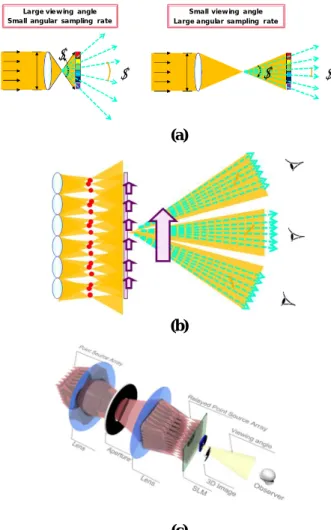
system has fixed viewing direction which usually coincides with the optic axis of the system. Many viewing angle enhancing techniques enlarge the viewing angle with fixed viewing direction. In this previous approach, however, is achieved at the expense of the angular sampling rate of the light rays. Figure 4(a) shows this fact. Since the elemental image is pixilated, the number of the light rays which can be reconstructed by one elemental lens is limited by the number of pixels which are assigned to the elemental lens. Assuming the number of the elemental lenses and the total pixel count of the display panel are constant, the angular sampling rate, i.e. inverse of the angular separation between neighboring light rays, is inversely proportional to the viewing angle as shown in Fig. 4(a). Therefore there is a trade-off relation between the viewing angle and the angular sampling rate. The angular sampling rate defines angular density of the 3D image reconstruction which determines the continuity of the parallax. Considering the continuity of the parallax is one of the main factors for natural 3D perception, lowering the angular sampling rate to increase the viewing angle is not desirable.
The proposed method takes different approach. Instead of enlarging the viewing angle with fixed viewing direction, the proposed method controls the viewing direction maintaining small viewing angle. The small viewing angle is compensated by the viewer tracking system. Figure 4(b) shows the concept of the proposed method. In the proposed method, the viewing angle does not define the viewing freedom of the viewers but defines the error tolerance of the viewer tracking system. Therefore the narrow viewing angle of the conventional integral imaging is sufficient in the proposed method. Since the viewing angle is maintained to a low value, the angular sampling rate can be made high, providing natural and continuous parallax. Therefore, the proposed method can provide 3D images with high angular sampling rate over wide viewing region. In order to achieve viewing direction controllability, the proposed method uses 4-f illumination optics with dynamic aperture. As shown in Fig. 4(c), the point light source array is relayed through 4-f optics and the light direction from the relayed point light source array is controlled by the variable aperture at the Fourier plane of the 4-f system. By changing the lateral position of the aperture, the viewing direction can be controlled. Moreover, by deviating the aperture plane from the Fourier plane, the converging or diverging illuminations which are
equivalent to the curved lens array of the conventional method can also be achieved.
θ
∆θ θ ∆θ
Large viewing angle Small angular sampling rate
Small viewing angle Large angular sampling rate
(a)
(b)
(c)
Fig. 4. Viewing direction controllable integral imaging (a) tradeoff relation between the viewing angle and the angular sampling rate, (b) concept of the proposed method, (c) implementation of the proposed method using 4-f illumination optics
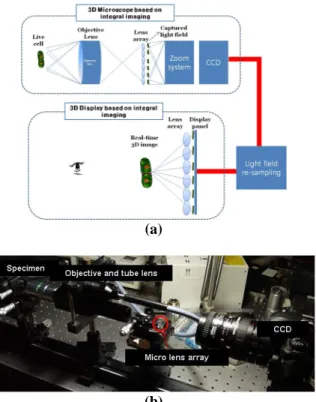
Finally, the 3D capture and display processes can be combined to provide real-time 3D images of the real-existing objects. Figure 5 shows integral imaging microscopy and 3D display system.7 Integral imaging microscopy captures elemental images of the 3D specimen, captured elemental images are processed for the integral imaging display system, and finally they are integrated into 3D images by the display. This system provides not only magnified image but also 3D information of the specimen, making it easier to understand 3D structure of the microscopic specimen. The scaling of the elemental images should be performed because different sets of the elemental
66-1 / J. –H. Park
IMID 2009 DIGEST •
lenses are used in the microscope and display system. The scaling coefficient is selected to minimize the distortion of the displayed 3D images.
(a)
(b)
Fig. 5. integral imaging microscopy combined with integral imaging display (a) concept (b)
implemented microscopy system
3. Summary
Recent progresses of integral imaging have been reviewed. Integral imaging can capture and display 3D images with full-parallax. Various techniques including the view reconstruction, elemental image masking, viewing direction control, and elemental image scaling enhance the performance of integral imaging and expand its application range.
Acknowledgement
This work was supported by the grant of the Korean Ministry of Education, Science and Technology" (The Regional Core Research Program / Chungbuk BIT Research-Oriented University Consortium).
4. References
1. G. Lippmann, Comptes-Rendus Academie des Sciences, 146, pp446 (1908).
2. B. Lee, J.-H. Park, and S.-W. Min, “Three-dimensional display and information processing based on integral imaging,” T.-C. Poon, New York, p333, 2006
3. J.-H. Park, H.-R. Kim, Y. Kim, J. Kim, J. Hong, S.-D. Lee, and B. Lee, Opt. Lett. 29, pp2734-2736 (2004).
4. J.-H. Park, G. Baasantseren, N. Kim, G. Park, J.-M. Kang, and B. Lee, Opt. Express 16, pp. 8800-8813 (2008).
5. G. Baasantseren, J.-H. Park, K.-C. Kwon, and N. Kim, Opt. Express 17, pp. 14405-14417 (2009). 6. J.-H. Park, M. Shin, and N. Kim, Society for
Information Display 2009 International Symposium (SID Display Week 2009) Digest of Technical Papers, pp. 607-610 (2009).
7. Y.-T. Lim, J.-H. Park, N. Kim, and K.-C. Kwon, Digital Holography and Three-Dimensional Imaging (OSA Optics and Photonics Spring Congress), paper DWB14 (2009).