Ship Stability
September 2013
Myung-Il Roh
Department of Naval Architecture and Ocean Engineering Seoul National University
Planning Procedure of Naval Architecture and Ocean Engineering
Ship Stability
Ch. 1 Introduction to Ship Stability
Ch. 2 Review of Fluid Mechanics
Ch. 3 Transverse Stability
Ch. 4 Initial Transverse Stability
Ch. 5 Free Surface Effect
Ch. 6 Inclining Test
Ch. 7 Longitudinal Stability
Ch. 8 Curves of Stability and Stability Criteria
Ch. 9 Numerical Integration Method in Naval Architecture
Ch. 10 Hydrostatic Values
Ch. 11 Introduction to Damage Stability
Ch. 12 Deterministic Damage Stability
Ch. 13 Probabilistic Damage Stability (Subdivision and Damage
Stability, SDS)
Ch. 8 Curves of Stability and
Stability Criteria
Statical Stability Curve
Definition and Purpose of the Statical Stability Curve
The statical stability curve is a plot of righting arm or righting moment against angle of heel for a given condition.
10
0 20 30 40 50 60 70 80
Angle of heel (φ )
∆ = const.
Righting arm
(GZ) (∆: displacement)
Statical Stability Curve
So far as the intact ship is concerned, the statical stability curve provides
useful data for judging the adequacy of the ship’s stability for the given
condition.
Definition and Purpose of the Statical Stability Curve - Calculation Method of “GZ” (1/2)
10
0 20 30 40 50 60 70 80
Angle of Heel (φ)
∆=
const.
Righting arm
(GZ) (∆: displacement)
Statical Stability Curve
1. At a certain angle of heel, calculate the static equilibrium position of the ship.
F G
F B
τ e
G
B B 1
τ
rF B
F G
G: Center of mass of a ship FG
: Gravitational force of a ship
B
: Center of buoyancy at initial position
FB: Buoyant force acting on a ship
B1
: New position of center of buoyancy after the ship has been inclined
φ
The fixed angle of heel means
that there is an external moment
that causes the ship to heel.
1. At a certain angle of heel, Calculate the static equilibrium position of the ship.
G
B
Definition and Purpose of the Statical Stability Curve - Calculation Method of “GZ” (2/2)
τ e
B 1
τ
rZ
F B
F G
Z
: The intersection point of a vertical line through the new position of the center of buoyancy(B
1) with the transversely parallel line to a
//
//
φ
2. By using the center of mass(G) and new position of the center of buoyancy(B 1 ),
calculate the righting arm “GZ”.
10
0 20 30 40 50 60 70 80
Angle of Heel (φ)
∆=
const.
Righting arm
(GZ) (∆: displacement)
Statical Stability Curve
G: Center of mass of a ship FG
: Gravitational force of a ship
B
: Center of buoyancy at initial position
FB: Buoyant force acting on a ship
B1
: New position of center of buoyancy after the ship has been inclined
Definition and Purpose of Cross Curves of Stability
Cross curves of stability are plots of righting arm against for various values of heel and for various values of displacement.
A statical stability curve for a certain value of displacement can be obtained from the cross curves of stability.
∆ (ton)
15° 30° 45° 60° 75° 90°
Cross curve of stability
∆ 1
∆ 2
∆ 4
∆ 3 Righting
arm(GZ)
(m)
Angle of heel(φ)
(°)
Statical
stability
curve
Method for Obtaining Cross Curves of Stability
G: Center of mass of a ship
B: Center of buoyancy at initial position
B1
: New position of center of buoyancy after the ship has been inclined
B 1
B G Z
K
Z: The intersection point of a vertical line through the new position of
the center of buoyancy(B
1) with the longitudinally parallel line to a waterline through the center of mass(G)
Then, the KN represents the righting arm.
The KN depends only on the
geometry of the submerged volume.
But KN is not dependent on the location of the center of mass G.
sin GZ = KN − KG φ
Suppose that the center of mass is located at K .
K
: Keel
N
N: The intersection point of a vertical line through the new position of
the center of buoyancy(B
1) with the transversely parallel line to a waterline through the point K
If the center of mass moves to
vertical direction, so it is located at G, the values of righting arm (GZ) is
//
//
//
sin KN − KG φ
sin KG φ
φ
( , )
KN = KN φ ∆
GZ (m)
∆ (ton)
15° 30° 45° 60° 75° 90°
Cross curve of stability
∆ 1
∆ 2
∆ 4
∆ 3
Statical stability curve
Righting arm
Displacement
Angle of heel φ (°)
Obtaining Statical Stability Curves from Cross Curves of Stability
• Three-dimensional cross curve of stability
Significance of the Statical Stability Curve (1/5)
The statical stability curve has a number of features that are significant in the analysis of the ship’s stability.
- The slope of the curve at zero degree, the peak of the curve, the range of stability, the angle of vanishing stability, and the area under the curve
10
0 20 30 40 50 60 70 80
Angle of heel ( φ )
∆ = const.
Righting arm (GZ)
Statical Stability Curve
(∆: displacement)
57.3°
The peck of the curve
The range of stability
The angle of vanishing stability
A B
Significance of the Statical Stability Curve (2/5) (1) The Slope of the Curve at Zero Degrees
10
0 20 30 40 50 60 70 80
Angle of heel ( φ )
∆ = const.
Righting arm (GZ)
Statical Stability Curve
(∆: displacement)
GM
The slope of the curve at zero degree is the metacentric height(GM).
sin GZ ≈ GM φ
Slop of the curve at φ =0
0 0
lim GZ lim GM sin
φ φ
φ
φ φ
→ = →
1( ) GM
= rad
0
, lim sin 1
φ
φ φ
→
=
57.3
= GM
If the righting arm continues to increase at the same rate as at the origin, it would be equal to GM at an inclination of 1 radian or 57.3°.
At small angles of heel
This is a convenient check for major error in the initial portion of the statical stability curve.
57.3°
Derivation
Significance of the Statical Stability Curve (3/5) (2) The Peak of the Curve
10
0 20 30 40 50 60 70 80
The peak of a statical stability curve identifies two quantities that are the maximum righting arm and the angle of maximum stability.
Maximum righting arm
Angle of maximum stability
The product of the displacement and the maximum righting arm is the maximum heeling moment that the ship can experience without capsizing.
In other words, if the ship is forced over to the angle of maximum stability by an externally applied constant heeling moment, the ship will capsize.
Angle of heel ( φ )
∆ = const.
Righting arm (GZ)
Statical Stability Curve
(∆: displacement)
The peck of the curve
Significance of the Statical Stability Curve (4/5)
(3) The Range of Stability and the Angle of Vanishing Stability
10
0 20 30 40 50 60 70 80
The range of stability
The range of stability is the range over which the ship has positive righting arms.
The angle of vanishing stability is the angle of heel at which the righting arm returns to zero.
If the ship heels beyond this angle, the moment caused by gravitation force and buoyant force will act to capsize, rather than to right, the ship.
The angle of vanishing stability
Angle of heel ( φ )
∆ = const.
Righting arm (GZ)
Statical Stability Curve
(∆: displacement)
Significance of the Statical Stability Curve (5/5) (4) The Area under the Curve
10
0 20 30 40 50 60 70 80
Righting arm (GZ)
10
0 20 30 40 50 60 70 80
Righting moment (GZ·∆)
The statical stability curve can be the plot of righting moment against angle of heel for a given condition by the product of the displacement and the righting arm.
The area under the curve, such as between angle A and angle B, represents the work required to heel the ship from angle A to angle B.
A B
When M is the moment at any angle of heel( φ ),
the work required to rotate the ship against this moment(M) through an angle(d φ )
= M d φ
The work(W) required to rotate from angle A to angle B:
B, ( in radinas) W = ∫
AM d φ φ
Derivation
Angle of heel ( φ )
∆ = const.
Statical Stability Curve
(∆: displacement)
Significance of the Statical Stability Curve (5/5) (4) The Area under the Curve – Total Area
10
0 20 30 40 50 60 70 80
Righting arm (GZ)
10
0 20 30 40 50 60 70 80
The total area between the statical stability curve (at zero degree to the angle of vanishing stability) and the horizontal axis represents the total work to capsize the ship from the upright position.
This is often referred to as dynamic stability .
The work(W) required to rotate from A to B:
, ( in radinas)
B
W = ∫
AM d φ φ
* The angle of vanishing stability
* The angle of vanishing stability is the angle of heel at which the righting arm returns to zero.
Angle of heel ( φ )
∆ = const.
Statical Stability Curve
(∆: displacement)
Righting moment
(GZ·∆)
Representation of Heeling Moments on the Statical Stability Curve
There are the nature of certain heeling force acting on the ship.
These forces may be caused by action of the beam winds, action of the waves in rolling the ship, lifting of heavy weights over the side, high-speed turn, etc.
By superimposing various heeling moment caused by these forces on a curve of righting moment, statical stability of the ship in any condition can be
evaluated.
10
0 20 30 40 50 60 70 80
Angle of heel ( φ )
∆ = const.
Statical Stability Curve
(∆: displacement)
Moment
Righting moment
Heeling moment
Representation of Heeling Moments on the Statical Stability Curve
- Significance between the Statical Stability Curve and Heeling Moments Curve (1/3)
10
0 20 30 40 50 60 70 80
Angle of heel ( φ )
∆ = const.
Statical Stability Curve
(∆: displacement)
Moment
Righting moment
Heeling moment
At angle C and D, the heeling moment is equal to the righting moment and the forces are in equilibrium.
C D
The vertical distance between the heeling moment and righting moment curves at any angles represents the net moment acting at that angle either to heel or right the ship, depending on the relative magnitude of the righting and heeling moments.
Net moment to right the ship
Net moment to heel the
ship Net moment
to heel the ship
C,D : the intersection points
of righting moment curve
with heeling moment curve
Representation of Heeling Moments on the Statical Stability Curve
- Significance between the Statical Stability Curve and Heeling Moments Curve (2/3)
If the ship is heeled to angle C, an inclination in either direction will generate a moment tending to restore the ship to angle C.
If the ship is heeled to beyond angle D, the ship will capsize.
The range of stability is decreased by the effect of the heeling moment.
10
0 20 30 40 50 60 70 80
Angle of heel ( φ )
C
C,D : the intersection points of righting moment curve with heeling moment curve
The range of stability
Statical Stability Curve Net moment to right
the ship Net moment
to heel the
ship Net moment
to heel the ship
Righting moment
Heeling moment
∆ = const.
(∆: displacement)
Moment
D
10
0 20 30 40 50 60 70 80
Angle of heel ( φ )
Representation of Heeling Moments on the Statical Stability Curve
- Significance between the Statical Stability Curve and Heeling Moments Curve (3/3)
C
Assumption) The ship was heeled to the left to angle E, has come to rest, and is about to be hilled in the opposite direction.
E
Energy imparted to the ship
as kinetic energy
Energy required to heel the ship from angle C to angle D
If the energy imparted to the ship as kinetic energy is larger than the energy required to heel the ship from angle C to angle D, the ship will capsize.
To reduce the danger of capsizing under these conditions, the area between the heeling and righting moment curves and between angle C and angle D should
D
Righting moment
Heeling moment
Moment ∆ = const.
(∆: displacement)
Statical Stability Curve
Evaluation of Stability
[Review] Statical Stability Curve
10
0 20 30 40 50 60 70 80
Angle of heel ( φ )
∆ = const.
Righting arm (GZ)
Statical Stability Curve
(∆: displacement)
GM
57.3°
The peck of the curve Maximum righting
arm
Angle of maximum stability The range of stability
The angle of vanishing stability
Slope of the curve at zero degree: metacentric height(GM)
sin GZ ≈ GM φ
The peak of a statical stability curve: maximum righting arm, angle of maximum stability
The range of stability: the range over which the ship has positive righting arms
The area under the curve, such as between angle A and angle B: the work required to heel the ship from angle A to angle B.
A B
The product of the
displacement and the maximum righting arm: the maximum heeling moment that the ship can experience without capsizing
What criteria is considered to evaluate the ship’s stability?
What is satisfactory stability? How much stable a ship must be?
Stability Criteria in General
Static considerations
- The angle of steady heel
- The range of positive stability
- The relative magnitudes of the heeling arm and the maximum righting arm.
The work and energy considerations (dynamic stability)
Various researchers and regulatory bodies prescribed criteria for deciding if the stability is satisfactory.
In this chapter, we present examples of such criteria based on consideration of actual shape and characteristics of the curves of
righting and heeling moment (or arm) for an undamaged ship (intact ship) through large angles of heel.
Features of the curves that warrant consideration from a purely static
viewpoint are:
Stability Criteria
- IMO Regulations for Intact Stability
10
0 20 30 50 60 70 80
Angle of heel ( φ [°]) Righting arm
(GZ [m])
A B
(a) Area A ≥ 0.055 (m⋅rad)
Area A: Area under the righting arm curve between the heel angle of 0° and 30°
Area B: Area under the righting arm curve between the heel angle of 30° and min(40°, φ
f)
※ φ
f: Heel angle at which openings in the hull submerge φ
m: Heel angle of maximum righting arm
(c) Area B ≥ 0.030 (m⋅rad)
(d) GZ ≥ 0.20 (m) at an angle of heel equal to or greater than 30°.
(b) Area A + B ≥ 0.09 (m⋅rad)
(e) GZ max should occur at an angle of heel equal to or greater than 25°.
φ m
※ After receiving the approval for the intact and damage stability of IMO regulation from owner and classification society, ship construction can be proceed.
∆ = const.
IMO Regulations for Intact Stability
(∆: displacement=F
B)
φ f 40
r GZ F B
τ = ⋅
(IMO Res.A-749(18) ch.3.1)
(f) The initial metacentric height GM o should not be less than 0.15 (m).
B
Merchant Ship Stability Criteria
- IMO Regulations for Intact Stability
(a) Area A ≥ 0.055 (m⋅rad) (c) Area B ≥ 0.030 (m⋅rad)
(d) GZ ≥ 0.20 (m) at an angle of heel equal to or greater than 30°
(b) Area A + B ≥ 0.09 (m⋅rad)
(e) GZ max should occur at an angle of heel preferably exceeding 30° but not less than 25°.
(f) The initial metacentric height GM o should not be less than 0.15 (m).
(IMO Res.A-749(18) ch.3.1)
※ After receiving approval of calculation of IMO regulation from Owner and Classification Society, ship construction can proceed.
IMO Regulations for Intact Stability
10
0 20 30 40 50 60 70 80
Angle of heel ( φ [°])
Righting arm (GZ)
A
φ m
∆ = const.
( ∆ : displacement)
φ f
GM 57.3 °
IMO recommendation on intact stability for passenger and cargo ships
Static considerations The work and energy considerations
(dynamic stability)
Area A: Area under the righting arm curve between the heel angle of 0° and 30°
Area B: Area under the righting arm curve
between the heel angle of 30° and min(40°, φ
f)
※ φ
f: Heel angle at which openings in the hull submerge
φ
m: Heel angle of maximum righting arm
Merchant Ship Stability Criteria
- IMO Regulations for Intact Stability
Special Criteria for Certain Types of Ships - Containerships greater than 100 m
These requirements apply to containerships greater than 100 m. They may also be applied to other cargo ships with considerable flare or large water plane areas. The administration may apply the following criteria instead of those in paragraphs of previous slide.
(a) Area A ≥ 0.009/C (m-rad)
(c) Area B ≥ 0.006/C (m-rad)
(d) GZ ≥ 0.033/C (m) at an angle of heel equal to or greater than 30°
(b) Area A + B ≥ 0.016/C (m-rad)
(e) GZ
max≥ 0.042/C (m)
(f) The total area under the righting arm curve (GZ curve) up to the angle of flooding φ
fshould not be less than 0.029/C (m-rad)
IMO Regulations for containerships greater than 100 m
In the above criteria the form factor C should be calculated using the formula and figure on the right-hand side.
2 2
B
100
m W
C dD d
C B KG C L
= ′
where, d: Mean draught (m)
2
D2
HD
b B l
D D h
B L
′ = + −
∑
D: Moulded depth of the ship (m) B: Moulded breadth of the ship (m)
KG: Height of the centre of gravity in (m) above the keel not to be taken as less than d
as defined in figure on the right-hand side.
(IMO Res.A-749(18) ch.4.9)
Area A: Area under the righting arm curve between the heel angle of 0°and 30°
Area B: Area under the righting arm curve
between the heel angle of 30°and min(40°,φf)
※φf: Heel angle at which openings in the hull submerge φm: Heel angle of maximum righting arm
Design Criteria Applicable to All Ships
- IMO Regulations for Severe Wind and Rolling Criteria (Weather Criteria)
Scope
The weather criteria should govern the minimum requirements for passenger or cargo ships of 24 m in length and over.
φ
0: Angle of heel under action of steady wind
φ
f: Angle of heel at which openings in the hull submerge
φ
1: Angle of roll to windward due to wave action φ
2: Angle of down flooding( φ
f) or 50°, whichever is less where,
φ
c: Angle of the second intersection between wind heeling arm and GZ(righting arm) curves
The ship is subjects to a steady wind pressure acting perpendicular to the ship’s center line which results in a steady wind heeling arm (lw
1).
IMO Regulations for Severe Wind and Rolling Criteria (Weather Criteria)
The ship is subjected to a gust wind pressure which results in a gust wind heeling arm (lw
2).
1
( )
1000 P A Z
lw m
g
= ⋅ ⋅
⋅ ⋅∇
1.5 ( ) lw = ⋅ lw m
(a) φ
0should be limited to 16° or 80% of the angle of deck edge immersion( φ
f), whichever is less.
Area a: The shaded area between angle φ
1and the first intersection of righting arm curve with heeling arm curve
Area b: The shaded area between the first intersection of righting arm curve with heeling arm curve and angle φ
2φ
0φ
1φ
2φ
clw
1lw
2b
a
A rm
2 2
( P = 504 N m / , g = 9.81 m s / )
A : Lateral projected area above water line.
Z : Vertical distance from the center of wind pressure to the center of water pressure
(b) Under these circumstances, area b should be equal to or greater than area a. The work and energy considerations
(dynamic stability)
(IMO Res.A-749(18) ch.3.2)
lw1
: steady wind heeling arm
lw2: gust wind heeling arm
War Ship Stability Criteria - U.S. Navy Criteria (1/2)
L: Center height of projected sail area above 0.5T A: Projected sail area (ft
2), V: average wind speed
(knots)
φ: Angle of heel (degree), ∆: Displacement (LT) φ : Angle of maximum righting arm (degree)
General U.S. Navy criteria are intended to ensure the adequacy of stability of all types and sizes of naval ships, as evidenced by sufficient righting energy to withstand various types of upsetting of heeling
moments.
(Example) Beam Winds Combined with Rolling
When winds of high velocity exist, beam winds and rolling are considered simultaneously.
If the water were still, the ship would require only sufficient righting moment to overcome the
heeling moment produced by the action of the wind on the ship’s “sail area”.
However, when the probability of wave action is taken into account, an additional allowance of dynamic stability is required to absorb the energy imparted to the ship by the rolling motion.
Draft
T/2
Center of Lateral Area
Center of
Lateral Resistance
L Wind, V
τ e
τ
rWar Ship Stability Criteria - U.S. Navy Criteria (2/2)
10
0 20 30 40 50 60 70 80
Angle of heel ( φ )
φ 0 φ 1 =25°
90 -10
-20
GZ: Righting Arm Curve HA: Heeling Arm Curve
A 1
A 2
φ m GZ 0
GZ max
25° left side about intersection point between HA and GZ
• Regulation
(b) A 2 ≥ 1.4·A 1
(a) GZ 0 ≤ 0.6·GZ max
Draft
T/2 Center of Lateral Area
Center of Lateral Resistance
L Wind, V
L: Center height of projected sail area above 0.5T A: Projected sail area (ft2) V: Average wind speed (knots) φ: Angle of heel (degree)
∆: Displacement (LT) φm: Angle of maximum
righting arm
2 2
0.0195 cos
1, 000 V A L
HA = ⋅ ⋅ φ
∆
: Static considerations
: The work and energy considerations (dynamic stability)
* The formula uses S.I units (except V in knots).
Stability is considered satisfactory if:
Stability Criteria of
Damage Stability
0
Angle of heel( φ ) Righting arm
(GZ)
φ m φ f
Equilibrium Point (Within 25~30 ° )
To be greater than 0.1 (m)
To be greater than 0.0175 (m·rad)
To be greater than 20 °
MARPOL Regulation for Damage Stability
(a) The final waterline shall be below the lower edge of any opening through which progressive flooding may take place.
(b) The angle of heel due to unsymmetrical flooding shall not exceed 25 degrees, provided that this angle may be increased up to 30 degrees if no deck edge immersion occurs.
(c) The statical stability curve has at least a range of 20 degrees beyond the position of equilibrium in association with a maximum residual righting arm of at least 0.1 meter within the 20 degrees range (d) The area under the curve within this range shall not be less than 0.0175 meter-radians.
• Regulation
MARPOL 1973/78/84 Annex I/25
※ φ
f: An angle of heel at which
openings in the hull submerge
φ
m: Angle of maximum righting arm
Damage Stability Criteria in Battleship*
10 20 30 40 50 Angle of heel( φ )
Righting arm
φ r = 8°
0
GZ(Righting Arm Curve)
HA(Heeling Arm Curve)
A 1
A 2
φ = min(45°, φ f ) φ 0
φ 0 (Initial Angle of Heel) ≤ 15°, A 2 ≥ 1.4·A 1
• Regulation
φ
r: Angle of heel in transverse wind
(It varies depending on displacement, φ
r= 8° in case of battleship with displacement of 9,000 ton.) φ
f: An angle of heel at which openings in the hull
submerge
[Example] 7,000 TEU Container Carrier at Homo. Scantling Arrival Condition
(14mt)
B
Merchant Ship Stability Criteria
- IMO Regulations for Intact Stability
(a) Area A ≥ 0.055 (m⋅rad) (c) Area B ≥ 0.030 (m⋅rad)
(d) GZ ≥ 0.20 (m) at an angle of heel equal to or greater than 30°
(b) Area A + B ≥ 0.09 (m⋅rad)
(e) GZ max should occur at an angle of heel preferably exceeding 30° but not less than 25°.
(f) The initial metacentric height GM o should not be less than 0.15 (m).
(IMO Res.A-749(18) ch.3.1)
※ After receiving approval of calculation of IMO regulation from owner and classification society, ship construction can proceed.
IMO Regulations for Intact Stability
10
0 20 30 40 50 60 70 80
Angle of heel ( φ [°])
Righting arm (GZ)
A
φ m
∆ = const.
( ∆ : displacement)
φ f
GM 57.3 °
IMO recommendation on intact stability for passenger and cargo ships
Static considerations The work and energy considerations
(dynamic stability)
Area A: Area under the righting arm curve between the heel angle of 0° and 30°
Area B: Area under the righting arm curve
between the heel angle of 30° and min(40°, φ
f)
※ φ
f: Heel angle at which openings in the hull submerge
φ
m: Heel angle of maximum righting arm
Effect of Free Surfaces of Liquids in Tanks
For all conditions, the initial metacentric height(GM) and the stability curves should be corrected for the effect of free surfaces of liquids in tanks.
GM = KB + BM − KG
0 0
0 0
( )
( ) )
G M KB BM KG GG KB BM KG GG GM GG
= + − +
= + − −
= −
Correction for the effect of free surfaces of liquids in tanks
0 0
KG → KG = KG + GG
0
F T SW
GG ρ i ρ
= ⋅
∑ ∇
i
T: Moment of inertia of liquid plane area in tank about longitudinal axis ρ
F: Density of liquid in tank
ρ
SW: Density of sea water
∇: Displacement volume of the ship
: Free surface moment
Initial metacentric height(GM)
How can you get the value of free surface moment?
(Assumption) Small angle of inclination
(IMO Res.A-749(18) ch.3.3)
G: Center of total mass
G0: Virtual risen center of gravity G1: New position of center of total mass G1’: The intersection of the line GZ with G0G1 B: Center of buoyancy
B1: New position of center of buoyancy after the ship has been inclined g: Center of the emerged volume
g1: Center of the submerged volume b: Center of liquid in tank
b1: New position of center of liquid in tank m: Metacenter of cargo hold
Effect of Free Surfaces of Liquids in Tanks
- 7,000 TEU Container Carrier at Homo. Scantling Arrival Condition
0F T SW
GG ρ i ρ
= ⋅
∑ ∇ : Free surface moment
(Example) Free surface moment of No. 4 heavy fuel oil tank (center) in No. 4 hold
14.44 l = m
10.26 h = m
10.44 b = m
i
T: Moment of inertia of liquid plane area in tank about longitudinal axis
3 3
(14.44) (10.44) 4
1, 369( )
12 12
T
i = l b ⋅ = ⋅ = m
.4 ( )
Free surface moment
0.98 1, 369 1, 342( )
NO HFOT C F i T
m ton ρ
= ⋅
= ⋅
= ⋅
ρ : Density of liquid in tank (heavy fuel oil) = 0.98 (ton/m
3)
-l/2 l/2
b/2
-b/2
y
dA = x ⋅ dy = l ⋅ dy
/ 2 / 2
2 2
/ 2 / 2
/ 2 3
2 / 2
( )
12
b b
T x
b b
b
b
i i y dA y l dy
l y dy l b
− −
−
= = = ⋅
= = ⋅
∫ ∫
∫
x
y
Effect of Free Surfaces of Liquids in Tanks
- 7,000 TEU Container Carrier at Homo. Scantling Arrival Condition
Free surface moments of all heavy fuel oil tanks
.4 ( )
Free surface moment NO HFOT C = 1, 342 ( m ton ⋅ )
Free surface moment Total HFOT = 7,109.2 ( m ton ⋅ )
0
F T SW
GG ρ i ρ
= ⋅
∑ ∇ : Free surface
moment
Effect of Free Surfaces of Liquids in Tanks
- 7,000 TEU Container Carrier at Homo. Scantling Arrival Condition
Calculating free surface moment of other tank at homo. scantling arrival condition(14mt)
0
7, 253.3
0.06( ) 120, 038
F T
SW
GG ρ i m
ρ
= ⋅ = =
∑ ∇
0 0
0.64 0.06 0.58 ( ) G M GM GG
m
= −
= − =
Initial metacentric height(GM) at this loading condition = 0.64(m)
Correction for effect of free surface of liquid in tanks is as follows:
0
F T SW
GG ρ i ρ
= ⋅
∑ ∇ : Free surface
moment
IMO Regulations for General Intact Stability Criteria
- 7,000 TEU Container Carrier at Homo. Scantling Arrival Condition
(a) Area A ≥ 0.055 (m⋅rad)
(c) Area B ≥ 0.030 (m⋅rad) (d) GZ ≥ 0.20 (m) at an angle of heel equal to or greater than 30°
(b) Area A + B ≥ 0.09 (m⋅rad)
(e) GZ max should occur at an angle of heel preferably exceeding 30° but not less than 25°.
(f) The initial metacentric height G 0 M should not be less than 0.15 (m).
Area A: Area under the righting arm curve between the heel angle of 0
°and 30
°Area B: Area under the righting arm curve
between the heel angle of 30° and min(40°, φ
f)
※ φ
m: Heel angle of maximum righting arm = 36.8°
0.148( )
Area A = m rad ⋅ ≥ 0.055( m rad ⋅ )
0.301( )
Area A + = B m rad ⋅ ≥ 0.090( m rad ⋅ ) A B
φ
f= 50°
※ φ
f: Heel angle at which openings in the hull
Area B: Area under the righting arm curve between the heel angle of 30° and 40°
0.153( )
Area B = m rad ⋅ ≥ 0.030( m rad ⋅ )
30
0.909( )
at angle of heel
GZ
= °= m ≥ 0.20( ) m
m
36.8
φ = ° ≥ 25 °
0.58
GM = m ≥ 0.15( ) m
φ m 57.3
°0.58 ( )
GM = m
0.909 1.050
All regulations are satisfied.
Merchant Ship Stability Criteria
- IMO Regulations for Intact Stability
Special Criteria for Certain Types of Ships - Containerships greater than 100 m
These requirements apply to containerships greater than 100 m. They may also be applied to other cargo ships with considerable flare or large water plane areas. The administration may apply the following criteria instead of those in paragraphs of previous slide.
(a) Area A ≥ 0.009/C (m-rad)
(c) Area B ≥ 0.006/C (m-rad)
(d) GZ ≥ 0.033/C (m) at an angle of heel equal to or greater than 30°
(b) Area A + B ≥ 0.016/C (m-rad)
(e) GZ
max≥ 0.042/C (m)
(f) The total area under the righting lever curve (GZ curve) up to the angle of flooding φ
fshould not be less than 0.029/C (m-rad)
IMO Regulations for containerships greater than 100 m
In the above criteria the form factor C should be calculated using the formula and figure on the right-hand side.
2 2
B
100
m W
C dD d
C B KG C L
= ′
where, d: Mean draught (m)
2
D2
HD
b B l
D D h
B L
′ = + −
∑
D: Moulded depth of the ship (m) B: Moulded breadth of the ship (m)
KG: Height of the centre of gravity in (m) above the keel not to be taken as less than d
as defined in figure on the right-hand side.
(IMO Res.A-749(18) ch.4.9)
Area A: Area under the righting arm curve between the heel angle of 0°and 30°
Area B: Area under the righting arm curve
between the heel angle of 30°and min(40°,φf)
※φf: Heel angle at which openings in the hull submerge φm: Heel angle of maximum righting arm
IMO Regulations for Intact Stability: Containerships greater than 100 m - 7,000 TEU Container Carrier at Homo. Scantling Arrival Condition
In the above criteria the form factor C should be calculated using the formula and figure on the right-hand side.
2 2
B
100
m W
C dD d
C B KG C L
= ′
where, d: Mean draught (m)
2
D2
HD
b B l
D D h
B L
′ = + −
∑
D: Moulded depth of the ship (m) B: Moulded breadth of the ship (m) KG: Height of the centre of gravity in m above the keel
(m) not to be taken as less than d C
B: Block coefficient
C
W: Water plane coefficient
(a) Area A ≥ 0.009/C = 0.117 (m⋅rad) (c) Area B ≥ 0.006/C = 0.078 (m⋅rad)
(d) GZ ≥ 0.033/C = 0.431 (m) at an angle of heel equal to or greater than 30 ° (b) Area A + B ≥ 0.016/C = 0.209 (m⋅rad)
(e) GZ max ≥ 0.042/C = 0.549 (m)
(f) The total area under the righting arm curve (GZ curve) up to
the angle of flooding φ
fshould not be less than 0.029/C = 0.379 (m⋅rad)
IMO regulations for containerships greater than 100 m
0.148( ) Area A = m rad ⋅
0.301( ) Area A + = B m rad ⋅
0.153( ) Area B = m rad ⋅
max
1.050(m) GZ =
0.4644( ) Area GZ Curve = m rad ⋅
30
0.909( )
at angle of heel
GZ
= °= m
All regulations are satisfied.
Design Criteria Applicable to All Ships
- IMO Regulations for Severe Wind and Rolling Criteria (Weather Criteria)
Scope
The weather criteria should govern the minimum requirements for passenger or cargo ships of 24 m in length and over.
φ
0: Angle of heel under action of steady wind
φ
f: Angle of heel at which openings in the hull submerge
φ
1: Angle of roll to windward due to wave action φ
2: Angle of down flooding( φ
f) or 50°, whichever is less where,
φ
c: Angle of the second intersection between wind heeling arm and GZ(righting arm) curves
The ship is subjects to a steady wind pressure acting perpendicular to the ship’s center line which results in a steady wind heeling arm (lw
1).
IMO Regulations for Severe Wind and Rolling Criteria (Weather Criteria)
The ship is subjected to a gust wind pressure which results in a gust wind heeling arm (lw
2).
1
( )
1000 P A Z
lw m
g
= ⋅ ⋅
⋅ ⋅∇
(a) φ
0should be limited to 16° or 80% of the angle of deck edge immersion( φ
f), whichever is less.
Area a: The shaded area between angle φ
1and the first intersection of righting arm curve with heeling arm curve
Area b: The shaded area between the first intersection of righting arm curve with heeling arm curve and angle φ
2φ
0φ
1φ
2φ
clw
1lw
2b
a
A rm
2 2
( P = 504 N m / , g = 9.81 m s / )
A : Lateral projected area above water line.
Z : Vertical distance from the center of wind pressure to the center of water pressure
(b) Under these circumstances, area b should be equal to or greater than area a. The work and energy considerations
(dynamic stability)
(IMO Res.A-749(18) ch.3.2)
IMO Regulations for Severe Wind and Rolling Criteria (Weather Criteria) - 7,000 TEU Container Carrier at Homo. Scantling Arrival Condition
(a) φ 0 is suggested to 16° or 80% of the angle of deck edge immersion( φ f ), whichever is less.
2 2
504( / ), 9.81( / ) P = N m g = m s
A : Lateral projected area above water line = 9,871(m2
)
Z : Vertical distance from center of wind pressure to center of water pressure
= (Vertical distance from base line to center of wind pressure) - (Vertical distance from base line to center of water pressure)
= 29.749 – 7.714 = 22.04(m)
First, we have to know the value of a steady wind heeling arm (lw
1).
1
504 9,871 22.04
0.1( ) 1000 1000 9.81 117,110
P A Z
lw m
g
⋅ ⋅ ⋅ ⋅
= = =
⋅ ⋅∇ ⋅ ⋅
29.749( ) m
7.714( ) m
Second, the angle of heel under action of steady wind( φ
0) is angle of intersection between GZ curve and lw
1. The φ
0is 4.5°.
The regulation (a) is satisfied.
φ
0φ
1φ
2φ
clw
1lw
2b
a
A rm
4.5°
1 ( )
1000 P A Z
lw m
g
= ⋅ ⋅
⋅ ⋅∇
IMO Regulations for Severe Wind and Rolling Criteria (Weather Criteria) - 7,000 TEU Container Carrier at Homo. Scantling Arrival Condition
(b) Under these circumstances, area b should be equal to or greater than area a.
First, we have to know the value of a gust wind heeling arm (lw
2).
2 1.5 1
1.5 0.1 0.15 ( ) lw lw
m
= ⋅
= ⋅ =
Second, we have to know the angle of roll ( φ
1).
1 109 1 2
109 0.99 0.93 1 0.887 0.054 21.963
k x x r s φ = ⋅ ⋅ ⋅ ⋅ ⋅
= ⋅ ⋅ ⋅ ⋅ ⋅
= °
Third, φ
2is angle of down flooding( φ
f) or 50°, whichever is less. We assume that φ
2for this container carrier is 50°.
Forth, the area a is 0.0384 (m·rad) and the area b is 0.3661 (m·rad).
The regulation (b) is satisfied.
φ
0φ
1φ
2φ
clw
1lw
2b
a
A rm
17.463
− °
21.963
= °
4.5°
Area a: The shaded area between angle
φ
1and the first
intersection of righting arm curve with heeling arm curve
Area b: The shaded area between the first intersection of righting
arm curve with heeling arm curve and angle φ
2Reference Slides
Statical Stability Curve
B1
: New position of center of buoyancy corresponding displacement
Method for Obtaining Cross Curves of Stability
- Calculating for a Number of Waterline at Various Drafts and Angles of Heel (1/4)
*Weather deck: Any deck exposed to the outside
Righting arm(KN) is calculated for a number of waterlines at various drafts and angles of heel.
Assumption: There is a complete watertight envelope consisting of bottom, side shell and weather deck*.
B: Center of buoyancy at initial position
B 1
Righting Arm
B φ = 15 °
N
K: Keel
K
N: The intersection point of a vertical line through the new position of
the center of buoyancy with the longitudinally parallel line to a waterline through the point K
∆ (ton)
15°
Righting arm(KN)[m]
Angle of Heel
φ (°)
Righting Arm
B 2
B
K N
*Weather deck: Any deck exposed to the outside
Righting arm(KN) is calculated for a number of waterlines at various drafts and angles of heel.
Assumption: There is a complete watertight envelope consisting of bottom, side shell and weather deck*.
∆ (ton)
15°
Righting arm(KN)[m]
Angle of Heel φ (°)
B2
: New position of center of buoyancy corresponding displacement
B: Center of buoyancy at initial positionK: Keel
N
: The intersection point of a vertical line through the new position of the center of buoyancy with the longitudinally parallel line to a waterline through the point K
Method for Obtaining Cross Curves of Stability
- Calculating for a Number of Waterline at Various Drafts and Angles of Heel (2/4)
Righting Arm
B 3
B φ = 15 °
K N
*Weather deck: Any deck exposed to the outside
Righting arm(KN) is calculated for a number of waterlines at various drafts and angles of heel.
Assumption: There is a complete watertight envelope consisting of bottom, side shell and weather deck*.
∆ (ton)
15°
Righting arm(KN)[m]
Angle of Heel φ (°)
B3
: New position of center of buoyancy corresponding displacement
B: Center of buoyancy at initial positionK: Keel
N
: The intersection point of a vertical line through the new position of the center of buoyancy with the longitudinally parallel line to a waterline through the point K
Method for Obtaining Cross Curves of Stability
- Calculating for a Number of Waterline at Various Drafts and Angles of Heel (3/4)
Righting Arm
B 4
B φ = 15 °
K N
∆ (ton)
15° 30° 45° 60° 75° 90°
Cross curve of stability
∆ 1
∆ 2
∆ 4
∆ 3
Righting arm(KN) [m]
Angle of Heel φ (°)
*Weather deck: Any deck exposed to the outside
Righting arm(KN) is calculated for a number of waterlines at various drafts and angles of heel.
Assumption: There is a complete watertight envelope consisting of bottom, side shell and weather deck*.
B4
: New position of center of buoyancy corresponding displacement
B: Center of buoyancy at initial positionK: Keel
N
: The intersection point of a vertical line through the new position of the center of buoyancy with the longitudinally parallel line to a waterline through the point K
Method for Obtaining Cross Curves of Stability
- Calculating for a Number of Waterline at Various Drafts and Angles of Heel (4/4)
Sta ti ca ls ta bi lity c ur ve
Obtaining the Statical Stability Curves from the Cross Curves of Stability
Example) Given condition
- Displacement = 25,000 [ton]
- KG = 2.7 [m]
0 15 30 45 60 75 90
Angle of Inclination( ), degree φ
Righting arms(KN) from Cross Curves
0 1.17 2.24 3.57 3.79 2.02 1.52
0 -0.70 -1.35 -1.91 -2.34 -2.61 -2.7
Adjustment for actual center of mass(G) and sin φ
( = − KG sin φ )
Righting arms(GZ) 0 0.47 0.89 1.66 1.45 -0.59 -1.2
Calculation of Static Equilibrium Position of a Ship
Given: ( ) ( ) ( ) ( )
( ) ( ) ( ) ( ) ( ) ( )
0 0 0 0
0 0 0
, , ,
T
T L
z
F M M
φ θ
=
r
r r r
Find: r
*= z
*φ
*θ
*
T, where F ( ) r
*= 0, M
T( ) r
*= 0, M
L( ) r
*= 0
Assumption:
( ) ( ) ( ) ( )
( ) ( )
0 0 0 0
* *
0 0
*
, ,
z z δ z φ φ δφ
θ θ δθ
= + = +
= +
( ) ( )
T ( )
L
F M M
=
r
r 0
r
Governing equation of hydrostatic equilibrium ( ) ( )
( )
( ) ( ) ( )
( ) ( ) ( )
( ) ( ) ( )
[ ]
,
B G ext
T BT GT extT
L BL GL extL
T
F F F F
where M M M M
M M M M
z φ θ
+ +
= + +
+ +
=
r r r r
r r r r
r r r r
r
( ) ( ) ( )
( )
( ) ( ) ( )
( )
( ) ( ) ( )
( )
( ) ( ) ( )
( ) ( ) ( )
0 0 0
0 0 0
0
0 0 0 0
0 0 0 0
, ,
, ,
, ,
, ,
T T T
T
L L L L
z
F F F
F z z z
M M M
M z
z
M z M M M
z
φ θφ θ φ θ δ
φ θ δφ
φ θ
φ θ δθ
φ θ
∂ ∂ ∂
− ∂ ∂ ∂
∂ ∂ ∂
− =
∂ ∂ ∂
− ∂ ∂ ∂
∂ ∂ ∂
Given Find
Given
( ) 0 ( ) 0 ( ) 0 ( ) 0 ( ) 0 ( ) 0
* * *
, , z = z + δ z φ = φ + δφ θ = θ + δθ
( )
*! 0,
T( )
*0,
L( )
*0
F r = M r = ! M r ! = Check Yes
No
We find the solution, . z * , φ θ * , *
( )
1( )
0( )
0z = z + δ z
Iteration
( )
1( )
0( )
0φ = φ + δφ
( )
1( )
0( )
0θ = θ + δθ
Assumption
( ) 0 ( ) 0 ( ) 0 ( ) 0 ( ) 0 ( ) 0
* * *
, ,
z = z + δ z φ = φ + δφ θ = θ + δθ
( ) ( )
0
0 0
1
x
x x
x x f
f x
x
∂ =
− ∂
=
∴
( ) ( )
1 0
0
0
tan x x
x f x
x f
x
x = −
∂
= ∂
=
β
( ) ( )
0
0 1
0
x
x x
x x f
f x
x
∂ =
= ∂
−
* x
( ) x
f y =
x y
x 0
x 1
x 2
( )
x
0x x
x f
∂ =
∂
β ( ) ( )
x
nx n
n
n x
x x f
f x
x
=
+ ∂
− ∂
=
∴ 1
Newton-Rhapson Method
( ) x 0
f
( )
*! 0,
T( )
*0,
L( )
*0
F r = M r = ! M r ! = Check
[Reference] IMO Regulations for Severe Wind and Rolling Criteria
(Weather Criteria)
The Angle of Roll(φ 1 )
Rolling Period(T)
IMO Regulations for Severe Wind and Rolling Criteria (Weather Criteria) - The Angle of Roll (φ 1 )
The Angle of Roll ( φ 1 ) should be calculated as follows:
1 109 k x x 1 2 r s (degrees) φ = ⋅ ⋅ ⋅ ⋅ ⋅
where:
x
1: factor as shown in Table 1 x
2: factor as shown in Table 2 k: factor as follows:
k = 1.0 for round-bilged ship having no bilge or bar keels k = 0.7 for a ship having sharp bilges
k = as shown in table 3 for a ship having bilge keels, a bar keel of both
with OG = distance between the center of mass and the waterline (m) (‘+’ if center of mass is above the waterline, ‘-’ if it is below)
0.73 0.6 / r = ± ⋅ OG d
s: factor as shown in table 4
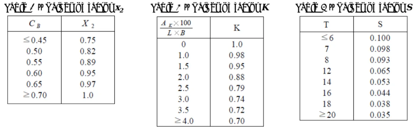
Table 1 – Values of factor x1 Table 2 – Values of factor x2 Table 3 – Values of factor K Table 4 – Values of factor S
(Intermediate values in Tables 1-4 should be obtained by linear interpolation.)
d
: Mean moulded draft of the ship (m)
CB: Block coefficient
L
: Waterline Length of the ship (m)
B: Moulded breadth of the ship (m)
AK
: Total overall area of bilge keels, or area of the lateral projection of the bar keel, or sum of these areas (m
2)
(IMO Res.A-749(18) ch.3.2.2.3)
IMO Regulations for Severe Wind and Rolling Criteria (Weather Criteria) - The Angle of Roll (φ
1)
- 7,000 TEU Container Carrier at Homo. Scantling Arrival Condition
The Angle of Roll ( φ
1):
1
109 k x x
1 2r s (degrees) φ = ⋅ ⋅ ⋅ ⋅ ⋅
1 109 k x x 1 2 r s φ = ⋅ ⋅ ⋅ ⋅ ⋅
d: Mean moulded draft of the ship (m) CB
: Block coefficient
L: Waterline Length of the ship (m) B: Moulded breadth of the ship (m)
AK
: Total overall area of bilge keels, or area of the lateral projection of the bar keel, or sum of these areas (m
2)
Lbilge keel: Length of bilge keel (m)
Bbilge keel
: Breadth of bilge keel (m)
109 0.99 0.93 1.0 0.887 0.054 21.963
= ⋅ ⋅ ⋅ ⋅ ⋅
= °
1) K = as shown in table 3 for a ship having bilge keels, a bar keel of both
( )
bilge keel bilge keel
2
2
151.2 115.2 0.45 2 32.4 ( )
A
KL B
m
= × ×
= − × × =
100 32.4 100
0.281 288 40
A
KL B
× = × =
× ×
0
100
0.281
0.02 1.0 0.02 0.99
1.0 1.0
K
at
A K K L B
×
= − × × = − × =
Table 3 – Values of factor K
2) x
1: factor as shown in table 1 40 2.83
14.15 B
d = =
Table 1 – Values of factor x1
1 1 / 0.28
/ 2.8 0.02 0.1
2.83 2.8 0.93 0.02
0.1 0.93
at B d
x = x
=− × B d −
= − × −
=
3) x
2: factor as shown in table 2 0.717
C
B=
Table 2 – Values of factor x22
1.0
x =
( )
4) 0.73 0.6
0.6 17.852 14.15
0.73 14.15
0.887 r OG
d
= ± ⋅
⋅ −
= +
=
*OG: From the waterline to the center of mass in the vertical direction
14
0.009 14 2 14.15 14 0.053 0.009
2 0.054
at T
s = s
=− × T −
= − × −
=
5) s: factor as shown in table 4 14.15
T =
Table 4 – Values of factor S
(IMO Res.A-749(18) ch.3.2.2.3)
IMO Regulations for Severe Wind and Rolling Criteria (Weather Criteria) - Rolling Period (T)
2 C B ( )
T s
GM
= ⋅ ⋅
where,
L: Waterline Length of the ship (m)
0.373 0.023( / ) 0.043( / 100)
C = + B d − L
The symbols in the above formula for the rolling period are defined as follows:
B: Moulded breadth of the ship (m) d: Mean moulded draft of the ship (m) C B : Block coefficient
A K : Total overall area of bilge keels, or area of the lateral projection of the bar keel, or sum of these areas (m 2 )
GM: Metacentric height corrected for free surface effect (m)
(IMO Res.A-749(18) ch.3.2.2.3)