Biomedical Sensors Biomedical Sensors
Intro. To. BME Intro. To. BME
Transducer(=sensor)
Intro. To. BME Intro. To. BME
Biosensor
• a device for the detection of an analyte that combines a biological component with a physicochemical detector component.
• It consists of 3 parts:
– the sensitive biological element
: biological material , a biologically derived material – the transducer or the detector element works in a
physicochemical way : optical, piezoelectric, electrochemical, etc
– associated electronics or signal processors that is primarily
responsible for the display of the results in a user-friendly way.
Intro. To. BME Intro. To. BME
• a device for the detection of an analyte that combines a biological component with a physicochemical detector component.
• It consists of 3 parts:
– the sensitive biological element
: biological material , a biologically derived material – the transducer or the detector element works in a
physicochemical way : optical, piezoelectric, electrochemical, etc
– associated electronics or signal processors that is primarily
responsible for the display of the results in a user-friendly way.
Properties of biosensor
• utilization of high
sensitivity & selectivity
of biological recognition
Intro. To. BME Intro. To. BME
Properties of biosensor
• Merits of biosensor
– rapid response time / real-time sensing
– continuous measurement / presence, absence or concentration of specific organic or inorganic substances
– accurate & potentially low operating cost
– easy to use / point-of-care diagnostics & home tests
• Drawbacks of biosensor
– need to design integrated, multitask systems
– need for methods to improve sensitivity, stability, and selectivity – high production cost
– slow development of noninvasive diagnostics – competition from conventional technology
Intro. To. BME Intro. To. BME
Type of biosensor
• Electrochemical sensor
– Biopotential sensors : ECG / EMG /EEG – Blood Gases and pH sensors
– Bioanalytical sensors : Enzyme-based or Microbial biosensor
• Mechanoelectrical sensor
– Hair-cell
– Displacement transducer – Temperature sensor
• Optical sensor
- SPR
- Optical Fiber
• Electrochemical sensor
– Biopotential sensors : ECG / EMG /EEG – Blood Gases and pH sensors
– Bioanalytical sensors : Enzyme-based or Microbial biosensor
• Mechanoelectrical sensor
– Hair-cell
– Displacement transducer – Temperature sensor
• Optical sensor
- SPR
- Optical Fiber
Intro. To. BME Intro. To. BME
1. Electrochemical sensor 1. Electrochemical sensor
1.1 The Electrolyte/Metal Electrode Interface
• Electrochemical cell
: two electrodes+electrolyte
• When potential VB < VA , Cell potential = VA-VB
• Half-cell potential : VA, VB
• Electrolyte : ion conductor
• Electrode : electronic conductor
• Electrochemical cell
: two electrodes+electrolyte
• When potential VB < VA , Cell potential = VA-VB
• Half-cell potential : VA, VB
• Electrolyte : ion conductor
• Electrode : electronic conductor
Intro. To. BME Intro. To. BME
electrolyte
electrode A electrode B
<structure of Electrochemical cell>
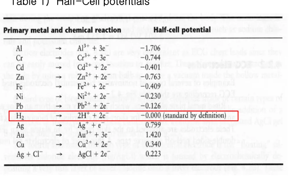
Half-cell potential
l
When a metal is placed in an electrolyte solution, a charge distribution is created next to the interface.
l
This distribution causes a half-cell potential.
l Primary affecting factors:
metal, ionic concentration, and temperature.
l NHE’s potential is 0 by definition
Intro. To. BME Intro. To. BME Distribution of charges at a
metal/electrolyte interface
l
When a metal is placed in an electrolyte solution, a charge distribution is created next to the interface.
l
This distribution causes a half-cell potential.
l Primary affecting factors:
metal, ionic concentration, and temperature.
l NHE’s potential is 0 by definition
Table 1) Half-Cell potentials
Intro. To. BME Intro. To. BME
Reference electrode
|
전 위
+
VR
VW Vcell Voltage
current density
Non-polarizable interface
Intro. To. BME Intro. To. BME
• Even if Vcell is changed, VR is constant and △Vcell = △Vw
• Reference electrode has Non-polarizable surface.
RE
|
전 위
+
VW Vcell
WE RE
Voltage
Polarizable interface
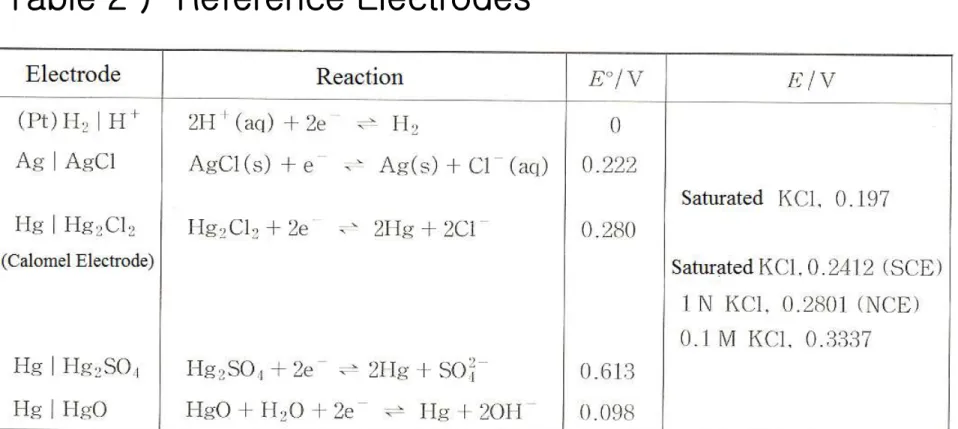
Normal Hydrogen Electrode(NHE)
• Internationally accepted primary reference
• defined as 0 volt
• Also called Standard Hydrogen Electrode
• Pt/H
2/H
+Intro. To. BME Intro. To. BME
• Internationally accepted primary reference
• defined as 0 volt
• Also called Standard Hydrogen Electrode
• Pt/H
2/H
+Ag/AgCl
• two reactions
• The first is at the Ag metal, while the second is at the AgCl/Cl-
interface: these reactions are reversable with the opposite reaction occuring at opposite electrode.
• The half cell potential of this electrode is maintained constant in Cl rich biological solutions.
Intro. To. BME Intro. To. BME
• two reactions
• The first is at the Ag metal, while the second is at the AgCl/Cl-
interface: these reactions are reversable with the opposite reaction occuring at opposite electrode.
• The half cell potential of this electrode is maintained constant in Cl rich biological solutions.
Examples of reference electrode
Table 2 ) Reference Electrodes
Intro. To. BME Intro. To. BME
The Electrolyte/Metal Electrode Interface
Intro. To. BME Intro. To. BME
Double Layer
• Fig. 1.2.3. Bard
• Helmholtz (Inner) layer: solvent molecules and other species specifically adsorbed. Distance xi, charge density Si.
• IHP (inner H plane) and OHP: boundary plane is where solvated ions can approach.
• Outside OHP is diffused layer .
• Fig. 1.2.3. Bard
• Helmholtz (Inner) layer: solvent molecules and other species specifically adsorbed. Distance xi, charge density Si.
• IHP (inner H plane) and OHP: boundary plane is where solvated ions can approach.
• Outside OHP is diffused layer .
Double Layer
• Metal charge (Qm): excess or deficiencies of electrons in a very thin (<0.1A) layer on metal surface. Sm=Qm/A[mC/cm
2]
• Solution charge(Qs): excess of cations or anions in the vicinity of electrode surface. SS=Qs/A[mC/cm
2]
• Double Layer: the whole array of charge species and oriented dipoles existing at the metal-solution
interface. Actual structure more complicated.
• Double layer capacitance(Cd) is defined at a given potential, typically in the range of 10 to 20 mF/cm
2.
• Metal charge (Qm): excess or deficiencies of electrons in a very thin (<0.1A) layer on metal surface. Sm=Qm/A[mC/cm
2]
• Solution charge(Qs): excess of cations or anions in the vicinity of electrode surface. SS=Qs/A[mC/cm
2]
• Double Layer: the whole array of charge species and oriented dipoles existing at the metal-solution
interface. Actual structure more complicated.
• Double layer capacitance(Cd) is defined at a given
potential, typically in the range of 10 to 20 mF/cm
2.
DL: cont’d
• The interaction of solvated ions in the diffuse layer with the charge metal involves only long range
electrostatic forces, independent of the chemical properties of the ions: nonspecific adsorption
.• Total excess charge density in diffused layer Ss= Si+Sd=-Sm.
• Thickness of diffused layer depends on ionic
concentration ~ 300 A. Potential in Fig.1.2.4 Bard
• The field strength is about 1E9 V/m/
• More details analysis can be found in Bard ch. 12.
DL: cont’d 2
Fig.1.2.4 in Bard )
Potential profile across the DL region in the absence of specific adsorption of ions
Factors affecting electrode reaction rate and current
Intro. To. BME Intro. To. BME
Equivalent circuit
Z
f=
Z
WC
dC
dR
sR
sR
ctR
s: solution resistance
C
d: double layer capacitance
Z
f: impedance of the Faradaic process R
ct: charge transfer resistance
Z
W: impedance to Mass transfer of the electroactive species
R
ctCurrent at the electrolyte/metal electrode Interface
Z
fC
dR
s• Capacitive current by C
dcharging
• Faradaic current by chemical reaction and charge(e.g. electron) transfer related with Z
fIntro. To. BME Intro. To. BME
Z
fCharge-injection mechanism of electrode materials
(Capacitive)
Intro. To. BME Intro. To. BME
(Faradaic)
(Faradaic/Capacitive)
Impedance Measurement (by Potentiostat )
R1 R2
- +
- +
Vin R3
Ref Counter Work A1
A2
- +
- +
Ro
A3 A4
Vout Vbias R1
R2
- +
- +
Vin R3
Ref Counter Work A1
A2
- +
- +
Ro
A3 A4
Vout Vbias
Potentiostat
• A1 (-)단 KCL 적용하면
• A2 출력단의 전압 =
• If R1=R2=R3, Vref = - (Vbias+Vin)
• 전류는 counter => working electrode로 흐름.
– Counter electrode : low impedence – Ref. electrode : high impedence
• 이제
\
• 즉 Vin, Vout을 보고 Rwork의 Mag., phase를 측정
• <장점> Reference 전류를 통해 전류가 흐르지 않으므로 이 전류의 상태가 보존 됨.
• Counter 전극이 변하더라도 이 저항의 변화는 측정에 관계없음
-
+ Vout
• A1 (-)단 KCL 적용하면
• A2 출력단의 전압 =
• If R1=R2=R3, Vref = - (Vbias+Vin)
• 전류는 counter => working electrode로 흐름.
– Counter electrode : low impedence – Ref. electrode : high impedence
• 이제
\
• 즉 Vin, Vout을 보고 Rwork의 Mag., phase를 측정
• <장점> Reference 전류를 통해 전류가 흐르지 않으므로 이 전류의 상태가 보존 됨.
• Counter 전극이 변하더라도 이 저항의 변화는 측정에 관계없음
Vout
Vref
Biopotential skin surface ECG electrodes:
(a) Rigid metal plate electrode and attachment strap,
(b) Suction-type metal electrode (c) Flexible Mylar electrode,and (d)disposable snap-type
Ag/AgCl electrode
(courtesy of Vermont Medical, Inc., Bellows Falls, VT)
1.2 Biopotential Sensors : ECG electrodes
Intro. To. BME Intro. To. BME
Biopotential skin surface ECG electrodes:
(a) Rigid metal plate electrode and attachment strap,
(b) Suction-type metal electrode (c) Flexible Mylar electrode,and (d)disposable snap-type
Ag/AgCl electrode
(courtesy of Vermont Medical, Inc., Bellows Falls, VT)
Electromyographic Electrodes(EMG)
The shape and size of the recorded EMG signals depends on
the electrical property of these electrodes and the recording location.
-The most common electrodes for noninvasive recordings are
circular discs, about 1cm in diameter, that are made of silver
or platinum.
-The electrodes for direct recording Are illustrated in Fig.
• The shape and size of
Intro. To. BME Intro. To. BME
The shape and size of the recorded EMG signals depends on
the electrical property of these electrodes and the recording location.
-The most common electrodes for noninvasive recordings are
circular discs, about 1cm in diameter, that are made of silver
or platinum.
-The electrodes for direct recording Are illustrated in Fig.
intramascular biopotential electrodes:
(a)bipolar and (b)unipolar configuration.
Electroencephalographic Electrodes(EEG)
• The most commonly used elctrodes for recording signals from the brain[electroencephalograms (EEG)] are cup electrodes and subdermal electrodes.
-Cup electrode:
• made of platinum
or tin approximately 5-10mm in diameter
• filled with a conducting electrolyte gel
• Attached to the scalp with an adhesive tape -Subdermal electrode:
• Basically fine platinum or stainless-steel needle electrodes
• 10mm long by 0.5mm wide
• Inserted under the skin
Intro. To. BME Intro. To. BME
• The most commonly used elctrodes for recording signals from the brain[electroencephalograms (EEG)] are cup electrodes and subdermal electrodes.
-Cup electrode:
• made of platinum
or tin approximately 5-10mm in diameter
• filled with a conducting electrolyte gel
• Attached to the scalp with an adhesive tape -Subdermal electrode:
• Basically fine platinum or stainless-steel needle electrodes
• 10mm long by 0.5mm wide
• Inserted under the skin
Biopotential Microelectrodes
(a)capillary glass microelectrode
- 0.1~10um in diameter by a heating and pulling process
(b) insulted metal electrode - a few micrometers by an
electrochemical etching process (c) solid-state multisite recording
microelectrode
- the ability to mass produce very small and highly sophisticated microsensors with highly
reproducible electrical and physical properties by solid-state
microfabrication techniques
Intro. To. BME Intro. To. BME
(a)capillary glass microelectrode
- 0.1~10um in diameter by a heating and pulling process
(b) insulted metal electrode - a few micrometers by an
electrochemical etching process (c) solid-state multisite recording
microelectrode
- the ability to mass produce very small and highly sophisticated microsensors with highly
reproducible electrical and physical properties by solid-state
microfabrication techniques
1.3 Blood Gases and pH Sensors : Oxygen Measurement
Principle of a polarographic Clark-type pO2 sensor.
: measure the partial pressure of O2 gas in a sample of air or blood.
The measurement is based on the principle of polarography.
At cathode: O2+2H2O+4e-ßà 4OH- which moves to anode to flow current
At Anode: Agßà Ag+ +e- Ag+ +Cl- ßà AgCl
The measured current is proportional to the pO2.
Intro. To. BME Intro. To. BME
Principle of a polarographic Clark-type pO2 sensor.
: measure the partial pressure of O2 gas in a sample of air or blood.
The measurement is based on the principle of polarography.
At cathode: O2+2H2O+4e-ßà 4OH- which moves to anode to flow current
At Anode: Agßà Ag+ +e- Ag+ +Cl- ßà AgCl
The measured current is proportional to the pO2.
Pt or Au
Ag/
Agcl
:
cross section of a Clark-type transcutaneous pO2 sensor -essentially a standardpolarographic pO2 sensor -attached to the surface of
the skin by double sided adhesive tape.
-at 43 C, the measured pO2 is the same as that in the underlying artery
-applied to monitor newborn baby(for adult skin this does not work)
Transcutaneous pO2 sensor
Intro. To. BME Intro. To. BME
:
cross section of a Clark-type transcutaneous pO2 sensor -essentially a standardpolarographic pO2 sensor -attached to the surface of
the skin by double sided adhesive tape.
-at 43 C, the measured pO2 is the same as that in the underlying artery
-applied to monitor newborn baby(for adult skin this does not work)
Skin
Time dependence of
light absorption by a peripheral vascular tissue bed illustrating the effect of arterial pulsation pulse oximetry relies on the
detection of the photoplethysmo- graphic signal. This signal is caused
by changes in arterial blood volume associated with periodic
contractions of the heart during systole.
(The IR signal reflected shows volume dependent absorption).
Intro. To. BME Intro. To. BME
Time dependence of
light absorption by a peripheral vascular tissue bed illustrating the effect of arterial pulsation pulse oximetry relies on the
detection of the photoplethysmo- graphic signal. This signal is caused
by changes in arterial blood volume associated with periodic
contractions of the heart during systole.
(The IR signal reflected shows volume dependent absorption).
pH electrodes
Principle of a pH electrode.
• two electrode:
reference & active,
-Ag/AgCl wire dipped in KCl solution
-Salt bridge is permeable to all ions.
-Active electrode is sealed with H-impermeable glass except at the tip, where it is
permeable only to H.
• V= -59mV*log10[H+]+C (C:constant, 25C) pH= -log10[H+]
V=59 *pH +C
Intro. To. BME Intro. To. BME
Principle of a pH electrode.
• two electrode:
reference & active,
-Ag/AgCl wire dipped in KCl solution
-Salt bridge is permeable to all ions.
-Active electrode is sealed with H-impermeable glass except at the tip, where it is
permeable only to H.
• V= -59mV*log10[H+]+C (C:constant, 25C) pH= -log10[H+]
V=59 *pH +C
Carbon Dioxide Sensors
Principle of a pCO2 electrode
electrodes for measurement of partial pressure of CO2 in blood or other liquid
(based on measuring the pH)
CO2+H2O ßà H2CO3ßàH+ +HCO3-
Change of pH generates potential between the glass pH and a
reference electrode(e.g., Ag/AgCl) that is proportional to the negative logarithm of the pCO2
Intro. To. BME Intro. To. BME
Principle of a pCO2 electrode
electrodes for measurement of partial pressure of CO2 in blood or other liquid
(based on measuring the pH)
CO2+H2O ßà H2CO3ßàH+ +HCO3-
Change of pH generates potential between the glass pH and a
reference electrode(e.g., Ag/AgCl) that is proportional to the negative logarithm of the pCO2
1.4 Bioanalytical Sensors : Enzyme-Based Biosensors
• Enzymes constitute a group of more than 2000 proteins having so-called biocatalytic properties.
• Most enzymes react only with specific substances.
The soluble enzymes are very sensitive to
both temperature and pH variations: also can be chemically inhibited.
• To ensure that the enzyme retains its catalytic
properties and can be reusable, we use an inert and stable matrix such as starch gel, silicon rubber, or polyacrylamide.
Intro. To. BME Intro. To. BME
• Enzymes constitute a group of more than 2000 proteins having so-called biocatalytic properties.
• Most enzymes react only with specific substances.
The soluble enzymes are very sensitive to
both temperature and pH variations: also can be chemically inhibited.
• To ensure that the enzyme retains its catalytic
properties and can be reusable, we use an inert and
stable matrix such as starch gel, silicon rubber, or
polyacrylamide.
• The action of specific enzymes can be utillized to construct a range of different biosensors.
ex)glucose sensor (
using the enzyme glucose oxidase(g.o.))Glucose + O
2--g.o.à gluconic acid +H
2O
2• Then either the amounts of either gluconic acid or H2O2 are detected chemically or amount of
consumed oxygen is measured.
• Biocatalytic enzyme-based sensors generally consist of an electrochemical gas-sensitive transducer or an ion-selective electrode ; with an enzyme immobilized in or on a membrane that serves as the biological
mediator.
Intro. To. BME Intro. To. BME
• The action of specific enzymes can be utillized to construct a range of different biosensors.
ex)glucose sensor (
using the enzyme glucose oxidase(g.o.))Glucose + O
2--g.o.à gluconic acid +H
2O
2• Then either the amounts of either gluconic acid or H2O2 are detected chemically or amount of
consumed oxygen is measured.
• Biocatalytic enzyme-based sensors generally consist of an electrochemical gas-sensitive transducer or an ion-selective electrode ; with an enzyme immobilized in or on a membrane that serves as the biological
mediator.
Microbial Biosensors
• The operation of microbial biosensors
(1)The substance is transported to the surface of the sensor
(2)The substance diffuses through the membrane to the immobilized microorganism.
(3)A reaction occurs at the immobilized organism.
(4)The products formed in the reaction are
transported through the membrane to the surface of the detector(products such as H2, CO2, or NH3 that are secreted by the micro-organism).
(5)the products are measured by the detector.
Intro. To. BME Intro. To. BME
Microbial Biosensors
• The operation of microbial biosensors
(1)The substance is transported to the surface of the sensor
(2)The substance diffuses through the membrane to the immobilized microorganism.
(3)A reaction occurs at the immobilized organism.
(4)The products formed in the reaction are
transported through the membrane to the surface of the detector(products such as H2, CO2, or NH3 that are secreted by the micro-organism).
(5)the products are measured by the detector.
When a sample of NO2 gas
Diffuses through the gas-permeable membrane, it is oxidized by the
Nitrobacter sp. Bacteria as follows:
2NO2 + O2 à 2NO3
The consumption of O2 around the membrane is determined by an electrochemical oxygen electrode.
Intro. To. BME Intro. To. BME
Principle of a NO2 microbial-type biosensor.
When a sample of NO2 gas
Diffuses through the gas-permeable membrane, it is oxidized by the
Nitrobacter sp. Bacteria as follows:
2NO2 + O2 à 2NO3
The consumption of O2 around the membrane is determined by an electrochemical oxygen electrode.
Type of biosensor
• Electrochemical sensor
– Biopotential sensors : ECG / EMG /EEG – Blood Gases and pH sensors
– Bioanalytical sensors : Enzyme-based or Microbial biosensor
• Mechanoelectrical sensor
– Hair-cell
– Displacement transducer – Temperature sensor
• Optical sensor
- SPR
- Optical Fiber
• Electrochemical sensor
– Biopotential sensors : ECG / EMG /EEG – Blood Gases and pH sensors
– Bioanalytical sensors : Enzyme-based or Microbial biosensor
• Mechanoelectrical sensor
– Hair-cell
– Displacement transducer – Temperature sensor
• Optical sensor
- SPR
- Optical Fiber
Intro. To. BME Intro. To. BME
2.
2. Mechanoelectrical Mechanoelectrical sensor sensor
2.1 Hair-cell as a natural transducer
Intro. To. BME Intro. To. BME
A
B
C
Motion of the Basilar Membrane
Intro. To. BME Intro. To. BME
C
D
Mechanical Sensitivity of a Hair Cell
A C
Intro. To. BME Intro. To. BME
B
D
The Mechanism of Mechanoelectrical Transduction by Hair Cell
Intro. To. BME Intro. To. BME
A Scanning Electron Micrograph of the Stereocilia
Intro. To. BME Intro. To. BME ( 3nm )
• Inductive displacement transducer
G:geometric form constant n: number of coil turns
:permeability of the magnetically susceptible medium inside the coil
• Measure displacement by changing either the self- inductance of a single coil or the mutual inductance
• The linear variable differential transformer(LVDT):
widely used inductive displacement transducer
m G n L =
2m
2.2 Displacement Transducers
Intro. To. BME Intro. To. BME
• Inductive displacement transducer
G:geometric form constant n: number of coil turns
:permeability of the magnetically susceptible medium inside the coil
• Measure displacement by changing either the self- inductance of a single coil or the mutual inductance
• The linear variable differential transformer(LVDT):
widely used inductive displacement transducer
m
Intro. To. BME Intro. To. BME
LVDT transducer
(a) electric diagram and (b) cross-section view (c) P :primary coil
S1,S2 :secondary coil
Output voltage versus core displacement of a typical LVDT transducer
A clip-on probe that fits snugly around the blood vessel
– Contains electrical coils – Coil is excited by an AC current.
– A pair of very small biopotential electrodes are attached.
– The flow-induced voltage is an AC voltage at the same freq. as the
excitation voltage.
•Measuring blood flow through an exposed vessel
Intro. To. BME Intro. To. BME
A clip-on probe that fits snugly around the blood vessel
– Contains electrical coils – Coil is excited by an AC current.
– A pair of very small biopotential electrodes are attached.
– The flow-induced voltage is an AC voltage at the same freq. as the
excitation voltage.
Electromagnetic blood-flow probe.
• Measuring blood flow through an exposed vessel
– use an electromagnetic flow transducer.
– blood vessel of diameter l – uniform velocity u
– If the vessel is placed in a uniform magnetic field ions in the blood vessel experience a force
As a result , the movement of the deflected charged particle produce an opposing force
– In equilibrium, these two forces are equal: thus potential difference V is
B r F r
Intro. To. BME Intro. To. BME
• Measuring blood flow through an exposed vessel
– use an electromagnetic flow transducer.
– blood vessel of diameter l – uniform velocity u
– If the vessel is placed in a uniform magnetic field ions in the blood vessel experience a force
As a result , the movement of the deflected charged particle produce an opposing force
– In equilibrium, these two forces are equal: thus potential difference V is
) ( u B q
F r r r
´
=
)
0
(
l q V E
q
F r = r =
Blu V =
F r
F r
0Linear translational(a)and angular (b)displacement transducers.
Intro. To. BME Intro. To. BME
Potentiometer,Resistive-type transducer.
-convert either linear or angular displacement into an
output voltage.
Elastic resistive transducer.
- consist of a thin elastic tube filled with an
electrically conductive material
- The resistance of the conductor inside the
flexible tubing is given by
Plethysmography: volume-measuring method
Intro. To. BME Intro. To. BME
Elastic resistive transducer.
- consist of a thin elastic tube filled with an
electrically conductive material
- The resistance of the conductor inside the
flexible tubing is given by
A ) ( l R =
r
Intro. To. BME Intro. To. BME
Bonded-type strain gauge transducer
Strain gauge:bonded or un-bonded type
– In the case of bonded type, the strain gauge has a folded thin wire cemented to a semi-flexible backing material.
– Fractional change in the length (strain) is measured by fractional change in resistance.
Resistive strain gauge
(unbonded type)
blood
pressure transducer
Intro. To. BME Intro. To. BME
– Consist of multiple resistive wires(typically four) stretched between fixed and movable rigid frames.
– Changes in blood pressure during the pumping action of the heart apply a force on a the diaphragm that causes the
movable frame to move from its resting position.
– This causes the strain gauge wires to stretch or compress.
The capacitance C between two equal size parallel plates
The method that is most commonly used to measure displacement in capacitance transducers involve changing the separation distance d
between a fixed and a movable plate.
)
0 (
d C =
e e
r AIntro. To. BME Intro. To. BME
The capacitance C between two equal size parallel plates
The method that is most commonly used to measure displacement in capacitance transducers involve changing the separation distance d
between a fixed and a movable plate.
capacitive displacement transducer
A piezoelectric transducer consists of a small crystal (usually quartz) that
contracts if an electric field (usually in the form of a short voltage impulse) is applied across its plates.
Intro. To. BME Intro. To. BME
• Piezoelectric principle:
asymmetric crystal is
distorted by an applied force, the internal negative and
positive charges are reoriented, causing an
induced usrface charge, and this is proportional to the applied force.
2.3 Temperature measurement
• Body temperature is one of the four basic vital signs.
• measured on Surface or inside
• Thermistor & Thermometer
- Thermistor: require direct contact with the skin or mucosal tissues
- Thermometer: noncontact,measure body core temperature inside the auditory canal
Intro. To. BME Intro. To. BME
• Body temperature is one of the four basic vital signs.
• measured on Surface or inside
• Thermistor & Thermometer
- Thermistor: require direct contact with the skin or mucosal tissues
- Thermometer: noncontact,measure body core
temperature inside the auditory canal
Thermistor
Resistivity versus temperature characteristics of a typical thermistor.
RT=R0 exp[B(1/T-1/T0)]
R0 : the resistance at T0 (in K) RT: the resistance at T (in K)
B: material constant
Temperature sensitive trasducer made of compressed sintered metal oxides (Ni, Mn, Co)
Intro. To. BME Intro. To. BME
Resistivity versus temperature characteristics of a typical thermistor.
RT=R0 exp[B(1/T-1/T0)]
R0 : the resistance at T0 (in K) RT: the resistance at T (in K)
B: material constant
Thermometer
• measure the temperature of the ear canal wall near the tympanic
membrane, which is known to track the core temperature.
•Infrared radiation from the tympanic membrane is detected by detector.
•Canal is gold plated for better reflectivity
•Sensor is a pyroelectric sensor (IR detector). Surface emissivity of the object at certain temperature and wavelength is calibrated for
temperature change. (For example.
T=300K and 3 um wavelength, 5 % change of emissivity corresponds to a temperature change of one degree.
Intro. To. BME Intro. To. BME
Non-contact type
infrared thermometer
• measure the temperature of the ear canal wall near the tympanic
membrane, which is known to track the core temperature.
•Infrared radiation from the tympanic membrane is detected by detector.
•Canal is gold plated for better reflectivity
•Sensor is a pyroelectric sensor (IR detector). Surface emissivity of the object at certain temperature and wavelength is calibrated for
temperature change. (For example.
T=300K and 3 um wavelength, 5 % change of emissivity corresponds to a temperature change of one degree.
Type of biosensor
• Electrochemical sensor
– Biopotential sensors : ECG / EMG /EEG – Blood Gases and pH sensors
– Bioanalytical sensors : Enzyme-based or Microbial biosensor
• Mechanoelectrical sensor
– Hair-cell
– Displacement transducer – Temperature sensor
• Optical biosensors
- SPR
- Optical Fiber
• Electrochemical sensor
– Biopotential sensors : ECG / EMG /EEG – Blood Gases and pH sensors
– Bioanalytical sensors : Enzyme-based or Microbial biosensor
• Mechanoelectrical sensor
– Hair-cell
– Displacement transducer – Temperature sensor
• Optical biosensors
- SPR
- Optical Fiber
Intro. To. BME Intro. To. BME
3.1 Surface Plasmon Resonance(SPR)
• Optical biosensors based on the phenomenon of surface plasmon resonance are evanescence wave techniques. This utilises a property shown of gold and other
materials; specifically that a thin layer of gold on a high refractive index glass surface can absorb laser light, producing electron waves (surface plasmons) on the gold surface. This occurs only at a specific angle and wavelength of incident light and is highly dependent on the surface of the gold, such that binding of a target analyte to a receptor on the gold surface produces a measurable signal.
• Surface plasmon resonance sensors operate using a sensor chip consisting of a plastic cassette supporting a glass plate, one side of which is coated with a microscopic layer of gold. This side contacts the optical detection apparatus of the instrument. The
opposite side is then contacted with a microfluidic flow system. The contact with the flow system creates channels across which reagents can be passed in solution. This side of the glass sensor chip can be modified in a number of ways, to allow easy attachment of molecules of interest. Normally it is coated in or similar compound.
• Light, at a fixed wavelength is reflected off the gold side of the chip, at the angle of total internal reflection and detected inside the instrument. This induces the evanescent wave to penetrate through the glass plate and someway into the liquid flowing over the surface.
• The refractive index at the flow side of the chip surface has a direct influence on the behaviour of the light reflected off the gold side. Binding to the flow side of the chip has an effect on the refractive index and in this way biological interactions can be measured to a high degree of sensitivity with some sort of energy.
3. Optical Biosensors 3. Optical Biosensors
Intro. To. BME Intro. To. BME
• Optical biosensors based on the phenomenon of surface plasmon resonance are evanescence wave techniques. This utilises a property shown of gold and other
materials; specifically that a thin layer of gold on a high refractive index glass surface can absorb laser light, producing electron waves (surface plasmons) on the gold surface. This occurs only at a specific angle and wavelength of incident light and is highly dependent on the surface of the gold, such that binding of a target analyte to a receptor on the gold surface produces a measurable signal.
• Surface plasmon resonance sensors operate using a sensor chip consisting of a plastic cassette supporting a glass plate, one side of which is coated with a microscopic layer of gold. This side contacts the optical detection apparatus of the instrument. The
opposite side is then contacted with a microfluidic flow system. The contact with the flow system creates channels across which reagents can be passed in solution. This side of the glass sensor chip can be modified in a number of ways, to allow easy attachment of molecules of interest. Normally it is coated in or similar compound.
• Light, at a fixed wavelength is reflected off the gold side of the chip, at the angle of total internal reflection and detected inside the instrument. This induces the evanescent wave to penetrate through the glass plate and someway into the liquid flowing over the surface.
• The refractive index at the flow side of the chip surface has a direct influence on the behaviour of the light reflected off the gold side. Binding to the flow side of the chip has an effect on the refractive index and in this way biological interactions can be measured to a high degree of sensitivity with some sort of energy.
SPR : concept
Intro. To. BME Intro. To. BME
SPR : concept
Intro. To. BME Intro. To. BME
http://www.biacore.com
Features of SPR biosensor
•No Labeling
– No Fluorescence Dyes
• Real Time Measurement
– Insight to dynamic nature of binding system and layer formation
• Exceptional sensitivity within Localized Volume
– Small quantities of purified reagents are required
Intro. To. BME Intro. To. BME
•No Labeling
– No Fluorescence Dyes
• Real Time Measurement
– Insight to dynamic nature of binding system and layer formation
• Exceptional sensitivity within Localized Volume
– Small quantities of purified reagents are required
Extension of application
Both the electrical (gray traces) and the SPR responses (black traces) increased in magnitude when the stimulation intensity was increased when supra-threshold stimulation currents were applied.
The SPR responses were highly correlated with simultaneously recorded electrical responses.
nerve
Intro. To. BME Intro. To. BME Intro. To. BME
Electrical responses
SPR responses
Both the electrical (gray traces) and the SPR responses (black traces) increased in magnitude when the stimulation intensity was increased when supra-threshold stimulation currents were applied.
The SPR responses were highly correlated with simultaneously recorded electrical responses.
Kim et al.Opt. Letters 2008
3.2 Optical Fibers
Intro. To. BME Intro. To. BME principle of optical fibers. optical fiber illustrating
the incident and refracted light rays. The solid line shows the light ray escaping from the core
into cladding.The dashed line shows the ray undergoing total internal reflection inside the core.
• used to transmit light from one location to another.
• made from two concentric and transparent glass or plastic materials: core & cladding
• The index of refraction, n core:n
1, cladding:n
2, n
1>n
2• Snell’s law: n
1sinQ
1=n
2sinQ
2• If sin Q
2=1.0 , sin Q
cr= n
2/n
1• Any light rays that enter the optical fiber with incidence angles greater than Qcr are internally reflected inside the core of the fiber by the
surrounding cladding.
Intro. To. BME Intro. To. BME
• used to transmit light from one location to another.
• made from two concentric and transparent glass or plastic materials: core & cladding
• The index of refraction, n core:n
1, cladding:n
2, n
1>n
2• Snell’s law: n
1sinQ
1=n
2sinQ
2• If sin Q
2=1.0 , sin Q
cr= n
2/n
1• Any light rays that enter the optical fiber with incidence angles greater than Qcr are internally reflected inside the core of the fiber by the
surrounding cladding.
Sensing Mechanisms of Optic Fiber
Intro. To. BME Intro. To. BME
General principle of a fiber optic-based sensor:
the common feature of commercial fiber optic sensors for blood gas monitoring
Indicator-Mediated fiber Optic Sensors
The return light signal has a magnitude that is proportional to the
concentration of the specied to be measured.
Different indicator-
mediated fiber optic sensor configurations.
(a) the indicator is immobilized directly on a membrane positioned at the end of the fiber
(b) an indicator in the form of powder can also be physically retained in
position at the end of the fiber by a special permeable membrane
(c) or a hollow capillary tube.
Intro. To. BME Intro. To. BME
Principle of a fiber optic immunoassay biosensor
• Uses Evanescence coupling of the light along fiber.
• Biosensor to detect antibody antigen binding.
• The immobilized antibody on the surface of unclad portion of
the fiber capture antigen from the sample solution