이용자는 아래의 조건을 따르는 경우에 한하여 자유롭게
l 이 저작물을 복제, 배포, 전송, 전시, 공연 및 방송할 수 있습니다. 다음과 같은 조건을 따라야 합니다:
l 귀하는, 이 저작물의 재이용이나 배포의 경우, 이 저작물에 적용된 이용허락조건 을 명확하게 나타내어야 합니다.
l 저작권자로부터 별도의 허가를 받으면 이러한 조건들은 적용되지 않습니다.
저작권법에 따른 이용자의 권리는 위의 내용에 의하여 영향을 받지 않습니다. 이것은 이용허락규약(Legal Code)을 이해하기 쉽게 요약한 것입니다.
Disclaimer
저작자표시. 귀하는 원저작자를 표시하여야 합니다.
비영리. 귀하는 이 저작물을 영리 목적으로 이용할 수 없습니다.
변경금지. 귀하는 이 저작물을 개작, 변형 또는 가공할 수 없습니다.
공학박사 학위논문
교류-직류 마이크로그리드 인터링킹 컨버터의 고품질 전력제어기술
Interlinking Converter Control
Techniques to Improve Power Quality in Hybrid AC-DC Microgrids
울산대학교 대학원 전기공학부
PHAN DANG MINH
교류-직류 마이크로그리드 인터링킹 컨버터의 고품질 전력제어기술
Interlinking Converter Control
Techniques to Improve Power Quality in Hybrid AC-DC Microgrids
지도교수 이홍희
이 논문을 공학박사 학위논문으로 제출함.
2019 년 12 월
울산대학교 대학원 전기공학부
PHAN DANG MINH
심사위원장 전태원 (인)
심사위원 이홍희 (인)
심사위원 최성진 (인)
심사위원 이동춘 (인)
심사위원 정의헌 (인)
울산대학교 대학원
전기공학부
2019 년 12 월
Interlinking Converter Control
Techniques to Improve Power Quality in Hybrid AC-DC Microgrids
by
Phan Dang Minh
A Dissertation
Submitted to the Graduate School of University of Ulsan in partial fulfillment of the requirements for the degree of
Doctor of Philosophy
in
The Graduate School of University of Ulsan Department of Electrical Engineering
December 2019
1. Committee Chair Professor Tae-Won Chun Signature:
2. Committee Member Professor Hong-Hee Lee Signature:
3. Committee Member Professor Sung-Jin Choi Signature:
4. Committee Member Professor Dong-Choon Lee Signature:
5. Committee Member Doctor Eui-Heon Jung Signature:
School of Electrical Engineering University of Ulsan, Ulsan, Korea
December 2019
I would like to dedicate this dissertation to my beloved parents, my
sister and my lovely girlfriend, and all my relatives...
i
I take this moment to express my appreciation to all the people have given me their support and encouragement during my years at the University of Ulsan.
First of all, I would like to express my sincere gratitude to my supervisor, Professor Hong-Hee Lee, who had provided complete support and given me invaluable advice during my doctoral study at the University of Ulsan. Without his guidance, I could not finish my education. I will forever be grateful to him for his support and kindness.
I would like to thank all distinguished professors in the Committee Members: Prof. Tae- Won Chun, Prof. Hong-Hee Lee, Prof. Sung-Jin Choi, Prof. Dong-Choon Lee, and Dr.
Eui-Heon Jung for their helpful comments and valuable suggestions on my dissertation.
I would also like to thank Network-based Automation Research Center and Brain Korea 21 Plus Program at the University of Ulsan for the financial supports.
I thank all former and current members of Industrial Networks and Power Electronics Laboratory (INPEL) for the useful discussions, close friendship. I am also thankful to all my great friends for memorable moments during my lifetime in Korea.
Finally, I would like to thank my beloved parents, my sister and my lovely girlfriend, and all my relatives for the endless love, support, and encouragement throughout the period of my study and my life as well. I love you all dearly.
Ulsan, December 2019 Phan Dang Minh
ii
Hybrid AC-DC microgrids (HMGs) have been studied recently in order to simultaneously exploit AC and DC microgrids (MGs). This dissertation develops control techniques for interlinking converter (IC) which is utilized to link MGs in HMGs. With the proposed control techniques, IC simultaneously manages various AC and DC voltage quality issues along with power flow among MGs.
In islanded HMGs, where utility grid is not considered, power quality is seriously degraded with highly distorted bus voltage when nonlinear loads are applied. In order to obtain sinusoidal bus voltage, we propose an IC control scheme which maintains bus voltage by providing harmonic currents caused by the nonlinear load. Moreover, the active power between DC and AC distributed generations (DGs) is also accurately balanced by IC. In the proposed algorithm, the desired IC current is determined by only considering the IC terminal voltage instead of the load current. Consequently, power converters in HMGs are operated autonomously with low system cost because communication links among them are not needed.
When AC MG connects to the utility grid, HMGs become grid-connected HMGs. In grid-connected HMGs, we have considered different conditions such as: the abnormal grid voltage, the utilized nonlinear load and the wide variation of DC load power. A versatile IC control strategy is proposed in order to enhance HMGs power quality under such severe conditions. Without implementing any additional hardware compensator, IC with the proposed control scheme can mitigate various issues such as distortion, sag/swell and imbalance in AC voltage and DC bus voltage restoration despite of wide load power variation. Both the desired power and the current among MGs are provided by IC since IC
iii
constantly kept at the nominal voltage.
In grid-connected HMGs, DC bus voltage is highly ripple when single-phase inverter with variable frequencies (SPI-VF) is operated in DC MG. In order to eliminate the ripple voltage, we present an IC control strategy which can adaptively deal with ripple voltage at different frequencies by controlling IC ripple current. In the proposed approach, instead of SPI current/voltage, only DC bus voltage is required to generate the IC ripple current reference. Besides that, power among MGs is also balanced by controlling IC fundamental current. As a consequence, AC MG can support DC MG in case DC load power changes widely. And DC bus voltage is well maintained at the nominal voltage without ripple.
Simulation and experimental results are carried out to validate performance of the proposed IC control techniques.
iv
Acknowledgements ... i
Abstract ... ii
Contents ... iv
List of Figures ... vi
List of Tables ... x
Abbreviations ... xi
Nomenclature ... xii
1. Introduction ... 14
1.1. Hybrid AC-DC Microgrids ... 15
1.2. Power Quality in Hybrid AC-DC Microgrids ... 17
1.3. Improvement of Hybrid AC-DC Microgrids Power Quality Using Interlinking Converter ... 19
1.4. About the Dissertation ... 20
2. Definitions, Effects and Solutions of Power Quality Issues in Hybrid AC-DC Microgrids ... 24
2.1. Power Quality Concept ... 25
2.2. Popular Power Quality Problems and Their Impacts ... 26
2.3. Discussion about Power Quality Problems ... 28
2.4. Power Quality Conditioning Techniques in AC Microgrid ... 33
2.5. Power Quality Conditioning Techniques in DC Microgrid ... 36
2.6. Conclusion ... 37
3. Power Quality Improvement in Islanded Hybrid AC-DC Microgrids ... 38
3.1. Introduction ... 39
3.2. System Description and Normalization Process ... 42
3.3. Proposed Interlinking Converter Control Strategy ... 45
3.4. Controller Design and Stability Analysis ... 47
3.5. Simulation Results ... 54
3.6. Experimental Results ... 60
3.7. Conclusion ... 65
4. Power Quality Improvement in Grid-connected Hybrid AC-DC Microgrids ... 66
4.1. Introduction ... 67
4.2. Sequences and Phase Extractor, Voltage Regulation with Shunt Compensator ... 70
4.3. Proposed Interlinking Converter Control Strategy ... 74
4.4. Controllers Design and Stability Analysis ... 81
v
5. Frequency-Adaptive DC Ripple Voltage Mitigation in Grid-connected Hybrid
AC-DC Microgrids... 104
5.1. Introduction ... 105
5.2. Principle of Ripple Voltage Mitigation ... 107
5.3. Proposed Interlinking Converter Control Strategy ... 110
5.4. Stability Analysis, Modeling and Design ... 115
5.5. Simulation Results ... 120
5.6. Experimental Results ... 124
5.7. Conclusion ... 130
6. Conclusion and Future Works ... 131
6.1. Conclusion ... 132
6.2. Future Works ... 133
References ... 134
Publications ... 140
vi
Fig. 1.1 HMGs general circuit. ... 16
Fig. 2.1 HMGs general circuit. ... 26
Fig. 2.2 AC bus voltage under abnormal grid voltage and nonlinear load condition. ... 26
Fig. 2.3 Common power quality problems in AC MG. ... 27
Fig. 2.4 Increase in motor heating and losses due to voltage unbalance. ... 32
Fig. 2.5 Shunt APF in AC MG. ... 33
Fig. 2.6 Series APF in AC MG. ... 34
Fig. 2.7 UPQC in AC MG. ... 35
Fig. 2.8 RE in DC MG. ... 36
Fig. 3.1 HMGs structure. ... 42
Fig. 3.2 Equivalent power circuit of HMGs with nonlinear load. ... 42
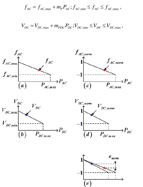
Fig. 3.3 Normalization process (a) AC droop characteristics, (b) DC droop characteristics, (c) Normalized fAC, (d) Normalized VDC, (e) Normalization process error enorm. ... 43
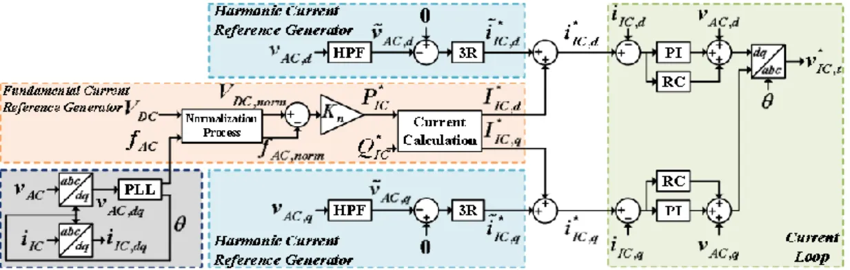
Fig. 3.4 The proposed IC control scheme in islanded HMGs. ... 45
Fig. 3.5 Bode diagram of Gc1 z with different KP. ... 47
Fig. 3.6 Unit step response of Gc1 z with different KI. ... 48
Fig. 3.7 Bode diagram of z Gl P z with different l. ... 49
Fig. 3.8 Pole-zero map of 1Go1 z with different Kr. ... 50
Fig. 3.9 Nyquist diagram of the system. ... 52
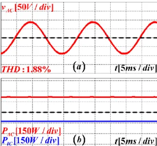
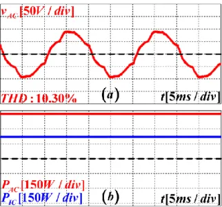
Fig. 3.10 Simulation results. Steady-state performance with linear load: (a) vAC and its THD, (b) PAC and PIC. ... 54
Fig. 3.11 Simulation results. Steady-state performance with nonlinear load and without harmonic current reference generator: (a) vAC and its THD, (b) PAC and PIC. ... 55
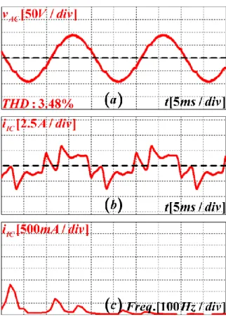
Fig. 3.12 Simulation results. Steady-state performance with nonlinear load and with the proposed IC control strategy: (a) vAC and its THD, (b) iIC, (c) FFT of iIC. ... 56
Fig. 3.13 Simulation results. Transient waveforms when: (a) and (b) AC MG connects to DC MG via IC, (c) and (d) Nonlinear load connects to HMGs. (a) PAC, PIC and PDC, (b) enorm, (c) PAC, PIC and PDC, (d) enorm. ... 57
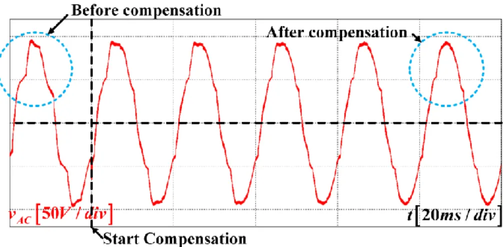
Fig. 3.14 Simulation results. Transient waveform of vAC when the proposed IC controller is activated. ... 59
vii
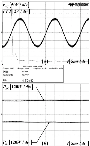
Fig. 3.16 Experimental results. Steady-state performance with linear load: (a) vAC and its
THD, (b) PAC and PIC. ... 61
Fig. 3.17 Experimental results. Steady-state performance with nonlinear load and without harmonic current reference generator: (a) vAC and its THD, (b) PAC and PIC. ... 62
Fig. 3.18 Experimental results. Steady-state performance with nonlinear load and with the proposed IC control strategy: (a) vAC and its THD, (b) iIC and its FFT. ... 63
Fig. 3.19 Experimental results. Transient waveforms of PAC and PIC when: (a) AC MG connects to DC MG via IC, (b) Nonlinear load connects to HMGs. ... 64
Fig. 3.20 Experimental results. Transient waveform of vAC when the proposed IC controller is activated. ... 64
Fig. 4.1 Grid-connected HMGs general circuit. ... 70
Fig. 4.2 Sequences and phase extractor. ... 71
Fig. 4.3 Equivalent transmission line with shunt compensation. ... 73
Fig. 4.4 The proposed IC control strategy. ... 74
Fig. 4.5 Simplified block diagram of the closed-loop system. ... 81
Fig. 4.6 Tracking error errIC d, with different KP i_ . ... 82
Fig. 4.7 Phase diagram of z Gl i_ P z with different l i_ . ... 83
Fig. 4.8 Pole-zero map of 1Go i_ z with different Kr i_ . ... 83
Fig. 4.9 Bode diagram of Go i_ z with different KR i_ . ... 84
Fig. 4.10 Pole-zero map of 1Go v_ z with different Kr v_ . ... 86
Fig. 4.11 Simulation results of case 1: (a) vAC waveform, (b) Magnified S1 before compensation, (c) Magnified S2 after compensation. ... 88
Fig. 4.12 Simulation results of case 2: (a) vAC waveform, (b) Magnified S1 before compensation, (c) Magnified S2 after compensation. ... 88
Fig. 4.13 Simulation results of case 3: (a) vAC waveform, (b) Magnified S1 before compensation, (c) Magnified S2 after compensation. ... 89
Fig. 4.14 Simulation results of case 4: (a) vAC waveform, (b) Magnified S1 before compensation, (c) Magnified S2 after compensation. ... 89
Fig. 4.15 Simulation results of case 5: (a) vAC waveform, (b) Magnified S1 before compensation, (c) Magnified S2 after compensation, (d) IC current. ... 91
Fig. 4.16 Simulation results of case 6: (a) vAC waveform, (b) Magnified S1 before compensation, (c) Magnified S2 after compensation, (d) IC current. ... 92
viii
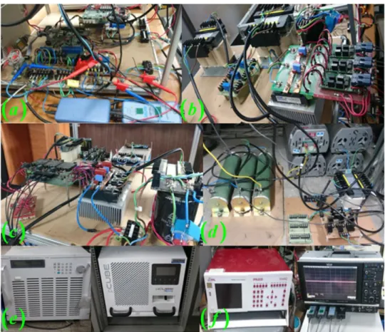
Source for power converters, (d) Power circuit, (e) DSP boards, (f) Linear loads, (g)
Nonlinear load. ... 95
Fig. 4.19 Experimental results of case 1: (a) vAC waveform, (b) Magnified S1 before compensation, (c) Magnified S2 after compensation. ... 96
Fig. 4.20 Experimental results of case 2: (a) vAC waveform, (b) Magnified S1 before compensation, (c) Magnified S2 after compensation. ... 96
Fig. 4.21 Experimental results of case 3: (a) vAC waveform, (b) Magnified S1 before compensation, (c) Magnified S2 after compensation. ... 97
Fig. 4.22 Experimental results of case 4: (a) vAC waveform, (b) Magnified S1 before compensation, (c) Magnified S2 after compensation. ... 97
Fig. 4.23 Experimental results of case 5: (a) vAC waveform, (b) Magnified S1 and power analysis before compensation, (c) Magnified S2 and power quality after compensation. 99 Fig. 4.24 Experimental results of case 6: (a) vAC waveform, (b) Magnified S1 and power analysis before compensation, (c) Magnified S2 and power quality after compensation. ... 100
Fig. 4.25 Experimental results of vDC restoration. ... 102
Fig. 5.1 HMGs general circuit. ... 107
Fig. 5.2 (a) SPI-VF circuit, (b) SPI-VF equivalent circuit in DC MG, (c) Principle of ripple voltage mitigation in DC MG. ... 108
Fig. 5.3 The proposed IC control strategy. ... 110
Fig. 5.4 Simplified block diagram of the IC current control loop. ... 115
Fig. 5.5 Bode diagram of Gc1 s with different KR1 and fSPI. ... 116
Fig. 5.6 Simplified block diagram of the IC ripple current reference generator loop. ... 118
Fig. 5.7 Pole-zero map of 1Go2 s with different KR2 and fSPI. ... 118
Fig. 5.8 Simulation results of vDC before compensation: (a) vDC with different fSPI, (b) vDC when fSPI 50Hz, (c) vDC when fSPI 60Hz, (d) vDC when fSPI 100Hz. ... 119
Fig. 5.9 Simulation results of vDC after compensation: (a) vDC with different fSPI, (b) vDC when fSPI 50Hz, (c) vDC when fSPI 60Hz, (d) vDC when fSPI100Hz. ... 119
Fig. 5.10 Simulation results of vDC before compensation in case of multiple SPIs and 1 60 fSPI Hz: (a, b) vDC and summarized ripple with different fSPI2, (c, d) vDC and FFT when SPI2 is not utilized, (e, f) vDC and FFT when fSPI261Hz, (g, h) vDC and FFT when 2 70 fSPI Hz, (i, j) vDC and FFT when fSPI290Hz... 121 Fig. 5.11 Simulation results of vDC after compensation in case of multiple SPIs and
1 60
fSPI Hz: (a, b) vDC and summarized ripple with different fSPI2, (c, d) vDC and FFT
ix
Fig. 5.13 Experimental results of DC bus nominal voltage restoration: (a) DC bus voltage, (b) Fundamental active power in HMGs, (c) IC phase current iIC a, and direct current iIC d, . ... 125 Fig. 5.14 Experimental results of vDC before compensation: (a, b) vDC and summarized ripple with different fSPI, (c, d) vDC and FFT when fSPI50Hz, (e, f) vDC and FFT when
SPI 60
f Hz, (g, h) vDC and FFT when fSPI 100Hz. ... 127 Fig. 5.15 Experimental results of vDC after compensation: (a, b) vDC and summarized ripple with different fSPI, (c, d) vDC and FFT when fSPI50Hz, (e, f) vDC and FFT when
SPI 60
f Hz, (g, h) vDC and FFT when fSPI 100Hz. ... 128
x
TABLE 2.1 Maximum Permissible Harmonic Current Distortion Allowed by IEEE 519-
1992 Standard. ... 29
TABLE 3.1 System Parameters. ... 54
TABLE 3.2 Summary of THD Values of Simulation Results. ... 56
TABLE 4.1 System Parameters. ... 87
TABLE 4.2 Test Cases. ... 87
TABLE 4.3 THD Values of Simulation Results. ... 93
TABLE 5.1 System Parameters. ... 120
xi
APF Active Power Filter
BESS Battery Energy Storage System
DG Distributed Generation
DFIG Doubly-Fed Induction Generator
DSOGI Dual Second-Order Generalized Integrator
ESS Energy Storage System
FFT Fast Fourier Transform
FLL Frequency-Locked Loop
HMGs Hybrid AC-DC Microgrids
HPF High-Pass Filter
IC Interlinking Converter
LHP Left-Half Plane
LPF Low-Pass Filter
MG Microgrid
PCC Point-of-Common-Coupling
PI Proportional-Integral
PNSE Positive Negative Sequences Extractor
PV Photovoltaic
PLL Phase-Locked Loop
QSG Quadrature-Signals Generator
RC Repetitive Controller
RE Voltage Eliminator
RES Renewable Energy Source
RMS Root Mean Squared
SPI Single-Phase Inverter
SPI-VF Single-Phase Inverter with Variable Frequency
THD Total Harmonic Distortion
UPQC Unified Power Quality Conditioner
VUF Voltage Unbalance Factor
xii
vDC, VDC* DC bus voltage and its reference
RDC Linear load in DC MG
fAC AC bus frequency
s Synchronization angle
vAC AC bus voltage
,
vAC, vAC, AC bus voltage in frame
,
VAC, VAC, AC bus fundamental voltage in frame
, ,
VAC , VAC, , AC bus fundamental voltage, positive sequence in
frame
, ,
VAC , VAC, , AC bus fundamental voltage, negative sequence in
frame
,
vAC d, vAC q, AC bus harmonic voltage in dq frame
* ,
vAC d, v*AC q, References of AC bus harmonic voltage in dq frame
, ,
VAC d, VAC q, , AC bus fundamental voltage, positive sequence in dq frame
* , ,
VAC d, VAC q* , , References of AC bus fundamental voltage, positive sequence in dq frame
, ,
VAC d, VAC q, , AC bus fundamental voltage, negative sequence in negative dq frame
* , ,
VAC d, VAC q* , , References of AC bus fundamental voltage, negative sequence in negative dq frame vIC, v*IC IC voltage and its reference
* ,
vIC d, v*IC q, References of IC voltage in dq frame
iIC IC current
,
iIC d, iIC q, IC current in dq frame
* ,
iIC d, iIC q* , References of IC current in dq frame
* ,
IIC d, IIC q* , References of IC fundamental current in dq frame
* ,
iIC d , iIC q*, References of IC harmonic current in dq frame
* , ,
IIC d, IIC q*, , References of IC fundamental current, positive sequence in dq frame
xiii
sequence in negative dq frame
*
, ,
IC abc
I References of IC fundamental current, negative
sequence in negative abc frame
ZIC IC output filter impedance
vG Grid voltage
ZG Grid side impedance
RAC Linear load in AC MG
, 5,7,
AC h h
i
Harmonic current caused by nonlinear load in ACMG
14
1. Introduction
Hybrid AC-DC microgrids (HMGs) consist of both AC and DC microgrids (MGs) which are interfaced by interlinking converters (ICs). Based on the HMGs general circuit with different conditions, this chapter determines severe HMGs power quality issues which are caused by nonlinear/unbalanced loads, abnormal grid voltage or single-phase inverter (SPI). In order to mitigate these power quality problems, conventional compensation methods in separate MGs are overviewed. However, most of them have many drawbacks such as low versatility, high cost due the requirement of additional hardware compensators. Therefore, instead of additional hardware compensators, the already existing ICs should be exploited to additionally compensate HMGs power quality, which is the main topic of this dissertation. In order to provide general viewpoint about this topic, this chapter also overviews previous studies about HMGs power quality compensation using ICs. By discussing about the presented approaches, their pros and cons can be realized. Based on that, dissertation objectives as well as contribution are then carried out.
15
1.1. Hybrid AC-DC Microgrids
In recent decades, the rapid growth of energy demand causes many remarkable problems such as the energy resources depletion and the greenhouse gas emission. To partially solve these issues, renewable energy is one of the most promising solution, and a large number of distributed generations (DGs) as well as distributed energy resources (DERs) are integrated into the power distribution and transmission systems [1]–[3]. Based on the penetration of renewable energy sources (RESs), the smart grid is introduced and implemented with modern technologies [4], [5]. According to the smart grid concept, microgrid (MG) is considered as a small scale of smart grid, and MG well known for its advantages such as: the power loss reduction in transmission system, the flexibility in linking DGs, loads and distributed energy storage systems (DESs) [6]–[8].
In terms of MG characteristics, it can be categorized into three types: the AC MG, the DC MG and the hybrid microgrids. The AC MG has been studied and widely adopted for a long time, and it is able to interface with the grid without power converters [6], [9].
Meanwhile, DC MG has been recently developed with the advantages of power electronics converters [10]–[13]. Compare with AC MG, it requires less of energy conversion stages in DC MG for utilizing the DERs such as photovoltaic (PV) and batteries. As a consequence, power loss and system efficiency are improved. In addition, DC loads are manufactured commercially for satisfying the increasing DC load demand. In order to utilize the existing AC MG together with the newly implemented DC MG, the hybrid AC- DC microgrids (HMGs) is a convenient solution [6], [14]–[19]. Basically, HMGs can inherit and exploit all the advancements and DERs of both AC and DC MGs. In HMGs, power electronics-based and bidirectional converters are used to link between MGs, and they are named as interlinking converters (ICs) [14], [15], [20]–[24].
16
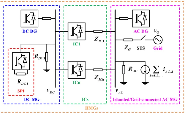
General HMGs circuit studied in this dissertation is provided in Fig. 1.1. In Fig. 1.1, HMGs consist of three main parts: the AC MG, the DC MG and the ICs. The AC MG can be operated in either islanded or grid-connected modes by opening or closing the static transfer switch (STS), respectively. In islanded AC MG, AC bus voltage vAC is regulated by the droop-based AC DG, while vAC relates to the grid voltage vG in grid-connected mode. In grid-connected mode, the grid is generally far from the common AC bus by means of a feeder impedance ZG as depicted in Fig. 1.1. In this study, vG is abnormal with sag, swell and unbalanced voltage. Both linear and nonlinear loads are utilized in AC MG.
In DC MG, the DC bus voltage vDC is regulated by the droop-based DC DG. At the common DC bus, besides the regular RDC1 load, we also apply a single-phase inverter (SPI) to supply power for the RDC2 load. MGs are linked by three-phase voltage source ICs whose output filter are denoted as ZIC in Fig. 1.1.
Fig. 1.1 HMGs general circuit.
17
1.2. Power Quality in Hybrid AC-DC Microgrids
In AC MGs, power quality problems includes the voltage and current harmonics, voltage sag/swell, voltage imbalance, etc. Because of the intensive and increasing growth of nonlinear loads such as rectifiers, adjustable speed motor drives, and switching power supplies, voltage and current harmonics are generally considered as the most severe problems in today networks. The AC MGs voltage quality is degraded since nonlinear loads injects harmonic current into distribution systems. Besides the harmonic voltage, voltage sags/swells and imbalance caused by abnormal grid voltage vG are also considered as costly power quality problems. These power quality problems regularly cause malfunctions or interruptions of power electronic devices or equipment, which may seriously affect to economic and production.
Due to severe impacts of low power quality, it mandatorily requires power quality improvement in power distribution system. To enhance power quality, power filters can be used. Common power filters are shunt active power filters (APFs), series APFs, dynamic voltage restorers (DVRs), hybrid APF and passive power filter, etc. In order to mitigate current harmonics generated by nonlinear load, the shunt APFs are mainly used.
Meanwhile, voltage disturbances such as voltage sag/swell, voltage unbalance, voltage distortion caused by abnormal grid is compensated by the DVR or series APF. Despite of the effective compensation performance, these compensating devices are able to deal with only one power quality issues, which means low versatility.
To deal with different power quality issues simultaneously, unified power quality conditioner (UPQC) has been introduced in recent years. UPQC is a combination of a shunt APF and a series APF which share a common DC link. Thereby, UPQC can effectively compensate the power quality issues such as current and voltage harmonics, voltage sag/swell, and voltage unbalance to protect sensitive loads and improve the AC
18
MGs power quality. In last decades, many studies about UPQC control strategy as well as utilization have been carried out. However, UPQC utilization also means high system cost and complexity since two types of power filters are required.
In practice, DC MG power quality is seriously degraded when a single-phase inverter (SPI) is tied to DC bus because SPI makes DC bus voltage highly ripple [25]. In other words, HMGs power quality is also affected with severe problems such as: high power loss and malfunction of sensitive loads [26]. To mitigate DC ripple voltage issue, either passive or active compensation methods can be applied. Passive compensation method is simple, however, with additional bulky capacitors, it also means large system size as well as short lifetime [27]. To overcome these drawbacks, active compensation method is preferred because of its high reliability as well as plug-and-play capability [25], [28], [29].
In active compensation method, it requires ripple voltage eliminators (REs) which are considered as power buffer to sink the ripple. Nevertheless, most of presented REs are able to mitigate ripple voltage at only one fixed frequency, such as 100Hz or 120Hz [25], [28], [29]. In case of SPI with variable operating frequency (SPI-VF), fixed characteristic RE is impossible to deal with ripple voltage which arbitrarily appears at different frequencies.
Thus, DC MG power is not ensured with conventional REs.
Additionally, in DC MG, the operation of sensitive loads is influenced by DC bus voltage which is regulated by droop-based DC DGs and load demand. So that, DC bus voltage should be constantly kept at the nominal voltage. However, in case of high load demand, regular RE is unable to reinforce the low DC bus voltage because RE does not contain any active power source. Similarly, when DC load power is low, DC bus voltage may be higher than the nominal voltage. And, BESSs are needed to absorb active power and lessen DC bus voltage.
19
1.3. Improvement of Hybrid AC-DC Microgrids Power Quality Using Interlinking Converter
In recent years, many studies have been presented in order to operate IC. However, most of them relate to power management in HMGs via IC. As we know, in HMGs, not only power management strategies but also power quality mitigation should be taken into account since there are so many kinds of disturbance in HMGs. HMGs power quality degradation may lead to malfunction of other equipment, high power loss and system stability [30]–[33].
In [34], to synthesize the droop characteristics of both AC and DC MGs, IC can be operated autonomously by using a normalization process. However, only the fundamental power is exchanged through the IC.
In [17], the linear relationship between the AC bus frequency and square of the DC bus voltage has been used to determine the fundamental active power exchanged in HMGs.
Nevertheless, only ideal AC and DC bus voltages are considered with linear loads.
In [35], IC is operated as a virtual shunt active power filter (APF) in order to mitigate the harmonic components introduced in the utility grid current. But, the proposed IC control strategy is implemented under ideal AC bus voltage. Therefore, this IC controller cannot be used with highly distorted AC bus voltages.
Authors in [20], [36] introduced a new modulation strategies for the IC to compensate the harmonics in point-of-common-coupling (PCC) voltage. Even though the power loss is reduced by using low switching frequency to control the IC, the total harmonic distortion (THD) of PCC voltage is higher than 4%. Moreover, it also requires the load current measurement, communication links and the central controller for operating IC, which is not simple because of the widely distributed loads in MGs. As a result, the total system cost is significantly increased and the IC is hard to operate autonomously in HMGs.
20
In [37], the IC with an inductor, transformer, capacitor, and inductor (LTC-L) topology is proposed for managing the power quality of AC MG in HMGs. Even though IC can work in different operation modes, a transformer is needed. Consequently, it may affect the total system cost, size and power loss. Furthermore, the experimental results are not provided to prove the feasibility in practice.
In [38], a doubly-fed induction generator (DFIG) is adopted to share the harmonic current with the IC. However, it may lead to some critical problem such as high circulating current and power loss in case of many parallel power circuits.
A centralized control strategy was proposed for power management in HMGs using parallel ICs [39]. The control strategy is based on instantaneous symmetrical component theory with a hysteresis current controller. However, high circulating current occurs when many parallel power converters are used in HMGs.
1.4. About the Dissertation 1.4.1. Objectives of the Dissertation
In this dissertation, both AC and DC MGs power quality are compensated simultaneously. However, instead of additional hardware compensators, the mandatory existing ICs are exploited. The IC can manage DC bus voltage restoration as well as AC voltage issues related with distorted, sag, swell and unbalanced AC voltage with only software algorithm. The final control target is to constantly maintain the AC and DC buses voltage about the nominal voltage regardless of the disturbances caused by nonlinear/unbalanced loads, abnormal grid voltage and SPI. The total harmonic distortion (THD) values of AC bus voltage after compensation must be lower than 5 % to comply with the IEEE 519-1992 standard.
21
1.4.2. Contributions of the Dissertation
In order to achieve the compensation objectives, different HMGs power quality problem are investigated. Then, theoretical analysis is conducted to propose the IC mitigation techniques. With the proposed IC control strategy, we also consider system stability by using various stability criterions. And the proposed control scheme is implemented in both simulation and experiment. Thanks to the PSIM software, simulation results of the proposed IC control strategies are provided. Meanwhile, experimental results are obtained by operating hardware prototypes in laboratory. Moreover, the TMS320F28335 Delfino™
32-bit MCU from Texas Instrument is utilized during our study. Main contributions of the dissertation are therefore listed as below:
Survey, introduction and analysis of various power quality problems in both AC and DC MGs. In AC MG, islanded as well as grid-connected modes are considered.
Power quality disturbances in AC MG are current harmonic, voltage distortion, voltage sag/swell, and voltage unbalance caused by nonlinear loads, unbalanced loads as well as abnormal grid voltage. On the other hand, DC MG power quality relates to inconstant and ripple DC bus voltage which are respectively resulted by wide DC load variation and SPI in DC MG. Basing on those analysis, appropriate compensation algorithms are proposed for operating ICs to concurrently eliminate these power quality problems in HMGs.
Development of a robust dual-loop control strategy for IC to compensate harmonic voltage in islanded HMGs. The proposed controller properly mitigates harmonic components in nonlinear load current to allow the common AC bus voltage contain only the fundamental component. Moreover, power demand between MGs is balanced by considering the normalized AC bus frequency and DC bus voltage.
22
Development of an advanced and versatile control strategy for the IL to compensate different power quality issues in grid-connected HMGs. The proposed IC control algorithm can simultaneously manage AC voltage sag, swell, unbalance together with distortion; and inconstant DC voltage under severe AC/DC load conditions as well as abnormal grid voltage. The proposed IC control scheme exploits the convenience offered by the repetitive controller (RC). Thus, harmonic compensation is much simpler than previous studies which utilize many resonant controllers. Instead of additional hardware compensators utilization, the proposed controller means software approach, which significantly reduces total system cost and size since only the mandatorily existing ICs are sufficient to deal with power quality issues. AC and DC voltage quality issues in HMGs are solved with excellent and versatile compensating performance.
Development of an effective IC control scheme which can adaptively deal with ripple voltage at different oscillation frequencies in grid-connected HMGs.
Additionally, DC bus voltage is accurately restored to the nominal voltage despite of the wide load variation.
Reduction of system size and cost because all the proposed IC control strategies can be implemented without the communication links. In addition, ICs can be operated autonomously with simple hardware requirement.
23
1.4.3. Outline of the Dissertation
The dissertation is organized as follows:
Chapter 1: The introduction of the dissertation is shown with the introduction of power quality issues in HMGs and typical solutions to deal with these problems. In addition, a review of previous studies about ICs control strategies is presented. Then, the dissertation objectives as well as contributions are given.
Chapter 2: Power quality definitions, typical power quality problems and their negative impacts are described. The overviews of common power conditioners such as shunt active power filter, series active power filter, dynamic voltage restorer, and unified power quality conditioner are presented.
Chapter 3: By considering the islanded HMGs with nonlinear load condition, voltage harmonic compensation as well as power balancing method for IC is developed in this chapter. After designing the controller parameters, both simulations and experimental results are shown to validate the compensation effectiveness of the proposed IC controller.
Chapter 4: This chapter presents a versatile and robust IC control strategy in grid- connected HMGs. Feasibility of the proposed IC controller is verified by considering different test cases in which grid voltage is abnormal. Analysis and design of the controller parameters are also carried out in detail. Simulation together with experimental results are provided in order to show the compensation performance.
Chapter 5: This chapter presents compensation method to adaptively suppress the ripple voltage at different frequencies in grid-connected HMGs. Moreover, DC bus voltage restoration is also considered with wide variation of load power. Experimental results is shown in this chapter to assess the feasibility of the proposed method.
Chapter 6: This chapter concludes the dissertation. Finally, future work of the research are also proposed.
24
2. Definitions, Effects and Solutions of Power Quality Issues in Hybrid AC-DC Microgrids
In this chapter, definitions of power quality are firstly given. Since hybrid AC-DC microgrids (HMGs) consist of both AC and DC microgrids (MGs), this chapter provides a detail discussion about popular power quality problems together with their negative impacts in each MG. After that, in order to separately solve MGs power quality issues, common power quality conditioners used in practice are overviewed. However, using different types of hardware compensators in HMGs may lead to severe problems such as high power loss, system cost and circulating current. As a result, we have considered an alternative approach where the existing interlinking converters (ICs) become power quality compensators. Therefore, MGs power quality is enhanced simultaneously by software algorithm only.
25
2.1. Power Quality Concept
According to the Institute of Electrical and Electronics Engineers (IEEE) 1100-1999 standard [40], the terminology “power quality” means: The concept of powering and grounding electronic equipment in a manner that is suitable to the operation of that equipment and compatible with the premise wiring system and other connected equipment.
Alternatively, in [41], the term “power quality” means: Power quality is the combination of voltage quality and current quality. Thus power quality is concerned with deviations of voltage and/or current from the ideal.
On the other hand, in [42], power quality problems are described as follows: “A power quality problem exists if any voltage, current or frequency deviation results in a failure or in bad operation of the customer’s equipment. The quality of the power supply consists basically of two elements, the supply reliability and the voltage quality”.
From the above descriptions, voltage quality is concerned with deviations of the voltage from the ideal. The ideal supply voltage is a single-frequency sinusoidal waveform with constant magnitude and frequency. The term voltage quality can be interpreted as the quality of the product delivered by the utility to the customers. Although the generators may supply a pure sinusoidal supply voltage, the current passing through the system impedance can cause a variety of disturbances to the voltage [41].
Similarly, current quality is concerned with deviations of the current from the ideal. The ideal current is a single-frequency sinusoidal waveform. An additional requirement is that the load current should be in phase with the supply voltage.
Power quality is often considered as a combination of voltage and current quality. In most of the cases, it is considered that the network operator is responsible for voltage quality at the point of common connection (PCC), the end user take the responsibility for the current quality at the PCC.
26
2.2. Popular Power Quality Problems and Their Impacts
As we know, nonlinear utilization in AC MG draws harmonic current ,
5,7, AC h h
i
insystem, this non-sinusoidal current cause harmonic voltage drop on system impedance and consequently lead to voltage distortion at the common AC bus as described in Fig. 1.1. In addition, grid faults on upstream transmission or distribution system, which is denoted as the voltage vG in Fig. 1.1, cause voltage sag and unbalance at the common AC bus. Fig.
2.2 shows the waveforms of the voltage at the common AC bus when vG is unbalanced, sag and swell.
Fig. 2.1 HMGs general circuit.
Fig. 2.2 AC bus voltage under abnormal grid voltage and nonlinear load condition.
27
In Fig. 2.2, AC bus voltage is under several power quality problems such as voltage distortion due to nonlinear load, voltage sag/swell, and voltage unbalance. These power quality problems seriously affect to the load connected at the common AC bus.
In [43], a survey indicates that voltage sag, harmonics, voltage unbalance, and voltage swell are the most common power quality problems strongly affected to operation of AC equipment or loads as in Fig. 2.3.
In DC MG, according to [44], ripple voltage is the most dominant problem.
Therefore, in this dissertation, the above voltage problems in both AC and DC MGs are taken into account. By employing the existing IC in HMGs, we develop a versatile and advanced control strategy which can effectively mitigate many voltage issues.
Fig. 2.3 Common power quality problems in AC MG.
28
2.3. Discussion about Power Quality Problems 2.3.1. Voltage Harmonic Distortion in AC Microgrid
Harmonics are signals whose frequency differs from the fundamental frequency of the power system. Moreover, the frequencies of the harmonic components are multiples of the fundamental frequency. In three-phase systems, characteristic harmonics of current/voltage have odd orders as (6n ± 1) (n = 1, 2, 3...).
In three-phase system, current harmonics are mainly generated by nonlinear loads, which are typically implemented from semiconductor devices [45]. Some common applications of nonlinear loads are adjustable speed drives, uninterruptible power sources (UPS) and AC/DC power supplies in domestic, industrial and commercial sectors [42], [46]–[48].
Numerous harmful effects caused by nonlinear loads are:
Causing voltage distortions that adversely affect to other sensitive loads.
Increasing of power loss and heat in transformers and line impedance.
Increasing of reactive power and heat on capacitor.
Production of pulsating and oscillating torques in turbines and generators.
Increasing of stator’s and rotor’s losses in motors.
False breaker tripping or fuse blowing.
Interferences in communication circuits and other EMI-related problems.
Because of the above negative impacts, different international standards have been published to restrict the amount of harmonics. TABLE 2.1 shows the maximum permissible individual harmonic current component consumed by loads, according to the IEEE 519-1992 standard.
29
According to TABLE 2.1, the total harmonic distortion (THD) of common bus voltage must be limited at 5%. To calculate common bus voltage THDV, the following equation is derived:
2 2
1
100%
ACh h V
AC
V
THD V
(2.1)
where VAC1 and VACh are respectively the root-mean-square (RMS) value of the fundamental and harmonic AC bus voltage, while h is the harmonic orders. In this dissertation, the IEEE 519-1992 harmonic standard is used as a reference for THD of the AC bus voltage so that the THD value of this voltage must be lower than the 5% limitation after compensation.
2.3.2. Voltage Sags in AC Microgrid
According to [41], voltage sag is defined as a decrease of the supply voltage between 0.1 and 0.9 per unit (pu) in RMS value at the power frequency for durations from 0.5 cycle to 1 minute. The term sag describes a short-duration voltage decrease. Generally, voltage sags relates to grid faults. However, energization of heavy loads or starting of large motors also cause voltage sags. Voltage sag in electrical system results in serious problem since they may generate high economic losses [49]–[52].
TABLE 2.1 Maximum Permissible Harmonic Current Distortion Allowed by IEEE 519-1992 Standard.
11
h 11 h 17 17 h 23 23 h 25 35h THD
4% 2% 1.5% 0.6% 0.3% 5%
30
In fact, the tolerances of devices connected to the supply network against voltage sags are not similar. Because sensitivity of electrical devices against different voltage sags is not fixed, the tolerance of each device against voltage sag depends on the duration of the sag and the magnitude of the voltage during the sag. Some remarkable effects caused by voltage sags are listed as follows:
Resetting or tripping of consumer electronics or domestic appliances.
Shutting down or restarting of computer-controlled industry processes.
Tripping of the adjustable speed drives due to the operation of their voltage protection circuits.
Torque and speed variations in the motors.
2.3.3. Voltage Swells in AC Microgrid
The voltage swell can be defined as an increase to between 1.1 and 1.8 p.u. in RMS voltage at the power frequency for durations from 0.5 cycle to 1 minute. So that, voltage swell is quite opposite to voltage sag. Similar to voltage sag, voltage swell also relates to grid fault, de-energization of heavy loads or stopping of large motors. Voltage swells temporarily appear during the single line to ground fault. However, unlike voltage sag, voltage swells does not commonly occur. The negative effects caused by voltage swell are quite similar to the effects caused by voltage sag. Besides that, voltage swell also leads to different serious problems such as:
Malfunction of sensitive electronic equipment.
Data errors in large computer system.
Interruption of equipment operation.
Damage or lifespan reduction of electrical and electronic devices.
31
2.3.4. Voltage Unbalance in AC Microgrid
A normal three phase supply has the three phases of same magnitude but with a phase shifted by 120◦. Any deviation (magnitude or phase) of one of the three signals means presentation of negative and/or zero sequence components. In order to evaluate the imbalance, the voltage unbalance factor (VUF) is defined [53]. VUF is expressed as the ratio between the negative sequence component VAC and positive sequence components
VAC as below:
AC100%
AC
VUF V V
(2.2)
Technically, voltage unbalance is caused by the imbalance in AC system. Imbalance includes unbalanced/single-phase load, as well as fault/unbalanced grid voltage.
Additionally, asymmetry in transformer winding impedance also costs voltage unbalance.
Based on the above reasons, voltage unbalance may occur and introduce some critical results as follows:
Reduction of motor efficiency.
High heat together with premature motor failure.
Introduction of zero sequence current component on neutral line.
32
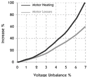
Moreover, in order to clarify the negative effect voltage unbalance, Fig. 2.4 depicts the increase of motor heat/loss by VUF. From Fig. 2.4, despite of small VUF, motor heat/loss are significantly high.
2.3.5. Voltage Ripple in DC Microgrid
Ripple is the residual periodic variation of the DC voltage within a power supply which has been derived from an alternating current source. Ripple voltage originates as the output of a rectifier or from generation and commutation of DC power. The ripple component is often small in magnitude relative to the DC component, but in absolute terms, ripple (as in the case of HVDC transmission systems) may be thousands of volts. Ripple itself is a composite (non-sinusoidal) waveform consisting of harmonics of some fundamental frequency which is usually the original AC line frequency, but in the case of switched- mode power supplies, the fundamental frequency can be tens of kilohertz to megahertz.
Ripple is wasted power, and has many undesirable effects in a DC circuit:
High heat and loss on components.
Undesired noise and distortion.
Improper operation of digital circuits.
Fig. 2.4 Increase in motor heating and losses due to voltage unbalance.
33
2.4. Power Quality Conditioning Techniques in AC Microgrid
As mentioned earlier, in AC MG, there are different power quality issues such as voltage distortion, sag, swell as well as unbalance. In order to specifically mitigate a voltage quality problem, additional hardware compensator(s) is required.
2.4.1. Shunt Active Power Filter
Voltage distortion is typically caused by nonlinear loads, which is denoted as a harmonic current source ,
5,7, AC h h
i
in Fig. 2.5. The presented harmonic current source results in the distorted AC bus voltage vAC and the degraded AC MG power quality. To mitigate distorted voltage, a shunt-connected power converter actively generate to the common AC bus a current whose value is ,5,7, AC h h
i
. It means that negative effect of the harmonic current source is countered by another current source as described in Fig. 2.5.Fig. 2.5 Shunt APF in AC MG.
34
2.4.2. Series Active Power and Dynamic Voltage Restorer
Besides the voltage distortion caused by the nonlinear loads, abnormal grid voltage vG also leads to AC MG power quality degradation. In this dissertation, vG given in Fig. 2.6 is not only sag/swell but also unbalanced. Therefore, vG is composed from two components: the fundamental voltage vG1 and the disturbance ˆvG. Despite of the abnormal vG, either series active power filter or dynamic voltage restorer (DVR) can be employed in order to obtain good vAC quality. As plotted in Fig. 2.6, series APF or DVR are integrated into AC MG by a coupling transformer whose across voltage is vc . Theoretically, vc should be ˆvG since there are in series. So, vAC is free from any adverse effect resulted by the sag/swell/unbalanced ˆvG.
Fig. 2.6 Series APF in AC MG.
35
2.4.3. Unified Power Quality Conditioner
In order to simultaneously compensate AC MG power quality issues, at least two types of hardware compensator are needed: the shunt APF together with the DVR or the unified power quality conditioner (UPQC). UPQC is composed of the shunt and series APFs which share a common DC link as introduced in Fig. 2.7. Theoretically, UPQC operation is a cooperation of shunt and series APFs performance so that UPQC control strategy is very complicated. Additionally, UPQC utilization also means that system is high in cost and large in size.
Fig. 2.7 UPQC in AC MG.
36
2.5. Power Quality Conditioning Techniques in DC Microgrid
In DC MG, ripple voltage is typically caused by the single-phase inverter (SPI) which makes DC bus voltage highly ripple [25]. In other words, DC MG power quality is also affected with severe problems such as: high power loss and malfunction of sensitive DC loads [26].
To mitigate DC ripple voltage issue, either passive or active compensation methods can be applied. Passive compensation method is simple, however, with additional bulky capacitors, it also means large system size as well as short lifetime [27]. To overcome these drawbacks, active compensation method is preferred because of its high reliability as well as plug-and-play capability [25], [28], [29]. In active compensation method, it requires ripple voltage eliminators (REs) which are considered as power buffer to sink the ripple as described in Fig. 2.8.
Fig. 2.8 RE in DC MG.
37
2.6. Conclusion
This chapter provides basic definitions about power quality. Based on that, we also discuss about power quality issues in AC and DC MGs which form the HMGs. Each power quality problem causes different negative impacts. Therefore, in order to solve the AC and DC voltage issues separately, commercial power quality conditioners are overviewed.
However, using separate power quality conditioners in each MGs means high system cost and complexity. As a result, the interlinking converters, which already exist in HMGs, should be exploited for power quality compensation purpose. This approach offers high versatility and convenience; and it is presented in the remained chapters where interlink converter control techniques have been developed to enhance HMGs power quality under different conditions.
38
3. Power Quality Improvement in Islanded Hybrid AC-DC Microgrids
In islanded hybrid AC-DC MGs (HMGs), the applied nonlinear loads severely degrade power quality with highly distorted bus voltage. This chapter develops an interlinking converter (IC) control technique in order to improve power quality of the islanded HMGs.
In the proposed control scheme, the IC controls the point-of-common-coupling (PCC) voltage by providing harmonic currents caused by the nonlinear load as well as the active power sharing between DC and AC distributed generations (DGs). In the proposed control scheme, IC current reference is determined by detecting o