```
1. INTRODUCTION
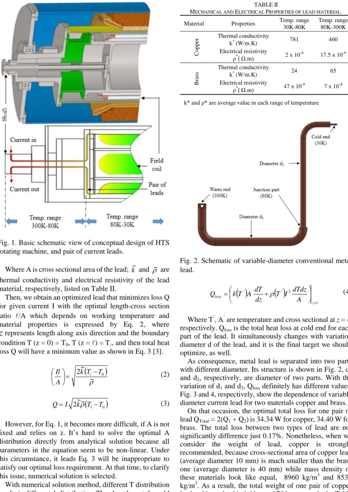
The development of a 3D electromagnetic design and power analysis of a 10-MW-class high-temperature superconducting (HTS) synchronous generator for wind power has been initiated by High Magnetic Field Lab, Electrical Engineering Department, Jeju National University. A conceptual design of the HTS magnet set which is utilized the field coil of generator rotor based on that has been completed. Detail dimension of the synchronous generator are available [1, 2]. Based on this optimized design specifications, this research will continue designing the current lead for 10 MW class HTS rotating machine to carry current from outside, then apply to field coil with desire specifications which are showed in Table I.
Certainly, there are several types of current leads are being used for the superconducting magnet system. It can be generally classified as: metal lead, partially HTS lead (a combination between metal section and HTS section), full HTS lead, and combined with conduction cooled or vapor cooled method, respectively. In order to minimize heat loss through current lead and increasing efficiency cool down of the lead, conduction cooled lead is selected for this design.
Moreover, basic schematic design of large scale HTS rotating machine is illustrated in Fig.1. It’s easily seen that, there are two ranges of temperature: from 300 K to 80 K, and others from 80 K to 30 K. The second term of temperature range is surely suitable for high temperature superconducting materials under their operation temperature, so we also concern the partially HTS lead, besides the conventional metal lead design.
Consequently, two critical causes for heat loss along the leads are: conduction heat loss and dissipation of Joule heating loss. The major difficulties in carrying out
calculations on leads is linked with the fact that the electrical resistivity and heat conductivity of the material from the leads are made relies on temperature distribution along its length. To figure out this issue, numerical solution is derived instead of complexly analytical solution, and it will be clearly explained hereafter.
In this paper, we will conceptually design and analyze steady-state thermal characteristic for two types of lead 1) conventional metal lead with two different materials: brass and copper 2) partially HTS leads with the HTS section (YBCO tape is used) attached to metal support structure, and then certainly connected to metal section (two different materials: brass and copper, respectively).
2.DESIGNOFCURRENTLEAD
2.1. Conventional Metal Lead
For a conduction cooled metal lead operating between room-temperature and cold end temperature, the steady state lead power differential equation over a unit lead length is given by:
0
~ ~ 02
2
2 + =
A TI dz
T Td k
A ρ (1)
TABLEI
PARAMETERS OF CURRENT LEAD AT OPERATING CURRENT I=232A.
Part I Temp. range
300K-80K
T1 300 (K) High temperature end T2 80 (K) Cold temperature end
1 1534 (mm) Length of lead Part II
Temp. range 80K-30K
T3 80 (K) High temperature end T4 30 (K) Cold temperature end
2 1667 (mm) Length of lead
Conceptual design of current lead for large scale high temperature superconducting rotating machine
T. D. Le, J. H. Kim, S. I. Park, and H. M. Kim*
Jeju National University, Jeju, Korea
(Received 20 May 2014; revised or reviewed 24 June 2014; accepted 25 June 2014)
Abstract
High-temperature superconducting (HTS) rotating machines always require an electric current of from several hundreds to several thousand amperes to be led from outside into cold region of the field coil. Heat losses through the current leads then assume tremendous importance. Consequently, it is necessary to acquire optimal design for the leads which would achieve minimum heat loss during operation of machines for a given electrical current. In this paper, conduction cooled current lead type of 10 MW-Class HTS rotating machine will be chosen, a conceptual design will be discussed and performed relied on the least heat lost estimation between conventional metal lead and partially HTS lead. In addition, steady-state thermal characteristic of each one also is considered and illustrated.
Keywords: Current leads, thermal characteristic, HTS rotating machine, conduction cooled lead
* Corresponding author: [email protected]
Fig. 1. Basic schematic view of conceptual design of HTS rotating machine, and pair of current leads.
Where A is cross sectional area of the lead; k~
and ρ~ are thermal conductivity and electrical resistivity of the lead material, respectively, listed on Table II.
Then, we obtain an optimized lead that minimizes loss Q for given current I with the optimal length-cross section ratio /A which depends on working temperature and material properties is expressed by Eq. 2, where
zrepresents length along axis direction and the boundary condition T (z = 0) = T0, T (z = ) = T, and then total heat loss Q will have a minimum value as shown in Eq. 3 [3].
( )
ρ~ 2k~T T0 A
Il l−
=
(2)
( 0)
~~ 2k T T I
Q= ρ l− (3)
However, for Eq. 1, it becomes more difficult, if A is not fixed and relies on z. It’s hard to solve the optimal A distribution directly from analytical solution because all parameters in the equation seem to be non-linear. Under this circumstance, it leads Eq. 3 will be inappropriate to satisfy our optimal loss requirement. At that time, to clarify this issue, numerical solution is selected.
With numerical solution method, different T distribution results in different A distribution. Then heat loss at the cold end of metal lead could be calculated based on the Eq. 4 [4]
below accordance with the T distribution.
TABLEII
MECHANICAL AND ELECTRICAL PROPERTIES OF LEAD MATERIAL. Material Properties Temp. range
30K-80K
Temp. range 80K-300K
Copper Thermal conductivity
k* (W/m.K) 781 460
Electrical resistivity
ρ*( Ω.m) 2 x 10⁻⁹ 17.5 x 10⁻⁹
Brass
Thermal conductivity
k* (W/m.K) 24 65
Electrical resistivity
ρ*( Ω.m) 47 x 10-9 7 x 10⁻⁸ k* and ρ* are average value in each range of temperature
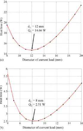
Fig. 2. Schematic of variable-diameter conventional metal lead.
( ) ( )
l z
loss A
I dTdz dz T
A dT T k Q
=
+
= ' ' ρ ' 2 ' (4)
Where T’, A’ are temperature and cross sectional at z = , respectively. Qloss is the total heat loss at cold end for each part of the lead. It simultaneously changes with variation diameter d of the lead, and it is the final target we should optimize, as well.
As consequence, metal lead is separated into two parts with different diameter. Its structure is shown in Fig. 2, d1 and d2, respectively, are diameter of two parts. With the variation of d1 and d2, Qloss definitely has different values.
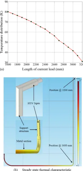
Fig. 3 and 4, respectively, show the dependence of variable diameter current lead for two materials copper and brass.
On that occasion, the optimal total loss for one pair of lead QTotal = 2(Q1 + Q2) is 34.34 W for copper, 34.40 W for brass. The total loss between two types of lead are not significantly difference just 0.17%. Nonetheless, when we consider the weight of lead, copper is strongly recommended, because cross-sectional area of copper lead (average diameter 10 mm) is much smaller than the brass one (average diameter is 40 mm) while mass density of these materials look like equal, 8960 kg/m3 and 8530 kg/m3. As a result, the total weight of one pair of copper lead and brass lead is 4.6 kg, and 78 kg, respectively. Table III illustrates detail summary optimized specifications of two leads.
Fig. 3. The relative between heat loss and diameter of copper lead (a) part I temperature range from 300 K to 80 K (b) part II temperature range from 80 K to 30 K.
Fig. 4. The relative between heat loss and diameter of brass lead (a) part I temperature range from 300 K to 80 K (b) part II temperature range from 80 K to 30 K.
TABLEIII
OPTIMIZED PARAMETERS FOR ONE PAIR OF LEAD.
Material Parameters Value
Copper
Diameter part I – d1 12 (mm) Diameter part II – d2 8 (mm)
Total weight 4.6 (kg)
Total loss 34.34 (W)
Brass
Diameter part I – d1 30 (mm) Diameter part II – d2 51 (mm)
Total weight 78 (kg)
Total loss 34.40 (W)
Fig. 5. Schematic of partially HTS lead, and HTS extension model design (a) bottom terminal block (b) top terminal block (c) square hollow support structure to attach HTS tapes.
2.2. Partially HTS lead
Fig. 5 specifically illustrates schematic of partially HTS lead, and designed HTS section model with bottom terminal block, top terminal block and square hollow support structure to attach HTS tapes. Each HTS tape will be attached to each side of square hollow support bar, then support bar connects the metal section lead and HTS section to each other. Thus, the total loss is conveniently expressed by Eq. 5.
hts metal
Total Q Q
Q = + (5)
Where Qmetal is the loss of metal section and is calculated as Eq. 4 between room temperature and 80 K. Meanwhile Qhts is the total conduction loss of 1) support structure with average thermal conductivity ks, cross sectional area As, length ls and 2) heat input to the magnet environment at T0 (30 K) by an HTS extension, of average thermal conductivity khts, cross sectional area Ahts, length lhts, and warm-end temperature Tw (80 K) is ideally by conduction, for which Eq. 6 follow:
TABLEIV
SPECIFICATIONS OF THE 2GHTS WIRE.
Conductor Property Value
Conductor type (Gd,Y)BCO
Thickness [mm] 0.16
Width [mm] 6
Critical current [A] @77 K, SF ≥120 Critical tensile strength [MPa] @77 K 550 (longitudinal direction)
TABLEV
TOTAL LOSS OF PARTIALLY HTS LEAD WITH DIFFERENT MATERIALS.
Material Heat loss Unit
Copper 31.43 W
Brass 26.95 W
Fig. 6. Steady state thermal characteristic of copper lead a) temperature distribution along the lead length b) 3D steady state thermal simulation and its temperature range.
( ) ( )
hts w hts hts s
w s s
hts l
T T A l k
T A T k
Q ~ 0 ~ − 0
− +
= (6)
Moreover, in the last few years, compared with first generation (1G) HTS wires, such as Bi2212 and Bi2223, second generation (2G) HTS wires, namely YBCO superconducting coated conductors, are becoming more and more attractive for current lead applications due to their high critical current density, low dependency of critical current Ic on the external magnetic field, low AC transport current loss, good mechanical properties, and reasonable cost [5-8]. If only taking thermal conductivity into consideration, Bi-2223 seems better than YBCO [9].
However, acting as an actual component in rotating machine, YBCO has more advantages over Bi-2223 at the field of electrical, magnetic and mechanicals performance.
At last, YBCO tapes 6mm x 0.16mm (width x thickness) made by SuperPower® 2G HTS wire, SCS6050 model is chosen.
Fig. 7. Steady state thermal characteristic of HTS extension a) temperature distribution along the lead length b) 3D steady state thermal simulation and its temperature range.
Furthermore, the specifications of the 2G HTS wire manufactured by SuperPower Corporation used to design the HTS field coils are listed in Table IV. Minimum critical current value of the 2G HTS wire has over 120 A at the cooling temperature of 77 K in the self-field condition. 2G HTS wire includes the copper stabilizer of 0.1 mm thickness. Within our system operating current is 232 A, then we use four turns of HTS tape, it means an average current of each tape is 58 A (at the highest temperature 80 K). This value reach about twice times least than the critical current 120 A measured under temperature 77 K along with self-field condition of 2G HTS. So, the average current value of four HTS tapes is surely sufficient to design the current lead for 10 MW class HTS synchronous generator.
Table V summaries the total loss of partially HTS lead.
Although, copper is a little bit larger loss (14.25%) compared to brass, copper is still strongly recommended in this case due to thermal conductivity’s copper (781 W/m.K) is much bigger than brass (30 W/m.K). It will be extremely good condition for cooling down the HTS tape during operation at temperature range from 30 K to 80 K, as well as the leads are lighter as previous recommendation.
3. CONCLUSIONS
This paper has discussed practical considerations related to applicable current lead designs for 10-MW-Class HTS synchronous generator. Two main points can be summarized. Firstly, a comparison of the total loss between conventional metal leads (brass and copper) and HTS partially lead, due to take advantages of temperature range 30K-80K. With conventional metal lead, variable-diameter can be used to decrease heat loss. For one pair of lead, although the heat loss difference between copper (34.34 W) and brass (34.40 W) is not significant, the copper one should be preferred because of its lower mass density, and smaller diameter, as a result the lead weight is much lighter than brass lead.
Secondly, with partially HTS section, we calculate the total loss with two different materials for metal section and support structure of HTS section. Once again, copper (31.43 W for one pair of lead) also prefer to brass (26.95 W) because of its high thermal conductivity which is a meaningful aspect to reduce HTS cooling down time.
And, temperature distribution along the lead and 3D steady-state heat transfer characteristic of the conventional
copper lead, partially HTS lead also performed detail in Fig. 7, Fig. 8, respectively.
It has just given basic considerations of lead design for 10-MW-Class HTS synchronous generator. Still, these results are quite useful to research engineers, academic researchers who are in charge of the large scale HTS rotating machine development. Base on this result, users can choose the lead model which is most applicable to their system. Not let up with these trends, the next research to get more detail of transient thermal characteristic for current lead will be surely conducted soon later.
ACKNOWLEDGMENT
This work was supported by the International Collaborative R&D Program and the Power Generation &
Electricity Delivery of the Korea Institute of Energy Technology Evaluation and Planning (KETEP) grant funded by the Korea government Ministry of Trade, industry & Energy (20118520020020), (20113020020020).
REFERENCES
[1] Ji Hyung Kim, “3D Electromagnetic Design and Power Analysis of a 10-MW-Class High-Temperature Superconducting Synchronous Generator for Wind Power”, Master of science thesis, Faculty of Applied Energy System, Graduate School, Jeju National University, 2013.
[2] J. H. Kim, H. M. Kim, “Electromagnetic Design of 10 MW Class Superconducting Wind Turbine using 2G HTS Wire,” Progress in Superconductivity and Cryogenics, vol. 15, No. 3, pp. 29-34, 2013.
[3] Yukikazu Iwasa, “Case Studies in Superconducting Magnets:
Design and Operational Issues,” Springer, Second edition, pp. 274, 2009.
[4] T. Ge, L. Ren, Q. He, F. Jiao, H. Dong, T. Jin, S. Zhou, “Hybrid current lead design of HTS SMES,” Physics Procedia, vol. 45, pp.
309-312, 2013.
[5] Y. Y. Xie, A. Knoll, and Y. Chen, “Progress in scale-up second-generation high-temperature superconductors at SuperPower Inc,” Physica C, vol. 426-431, pp. 849-857, 2005.
[6] K. Shiohara, S. Sakai, and S. ohki, “Transport performance of a HTS current lead prepared by the TFA-MOD processed YBCO tapes,” Physica C, vol. 469, pp.1870-1872, 2009.
[7] S. Fleshler, D. Buczek, and B. Cater, “Scale-up of 2G wire manufacturing at American Superconductor Corporation,” Physica C, vol. 469, pp. 1316-1321, 2009.
[8] A. Ballarino, “HTS current leads for the LHC magnet powering system,” Physica C, vol. 372-376, pp. 1413-1418, 2002.
[9] H. Zhang, Q. Li, J. Zong, “Development of low thermal conductivity Ag–Au alloy sheath Bi-2223 tape and design of a 20 kA HTS current lead,” Physica C, vol. 412-414, pp. 1217-1220, 2004.