Ⅰ. 서 론
다수의 치아가 상실되어 가철성 국소의치 치료를 필요로 하는 환자들에게, 잔존 치아 및 주변 조직의 건강을 오래도록 유지할 수 있도록 해 주는 것은 상 실된 치아를 회복해 주는 것 이상으로 중요한 일이 다. 그러기 위해서는 정확한 국소의치의 설계와 제 작이 요구되며, 특히 지대치에 작용되는 불필요한 외력을 줄이고, 지대치와 직접유지장치 간의 관계를 세밀히 파악할 필요가 있다. 잘못 설계된 국소의치 로 인하여 지대치에 불필요한 하중이 작용됨으로써 지대치의 건강도가 위협받고, 나아가 의치의 수명에 영향을 미칠 수 있기 때문에, 국소의치로부터 지대 치에 전달되는 외력의 크기는 지대치의 생리적 허용 한계를 넘지 않도록 적절한 설계가 되어야 한다.
국소의치 장착자의 지대치 주변에서 치주낭 깊이의 증가, 치아 동요도의 증가, 치조골 상실 등 바람직하 지 못한 반응이 발생한다는 많은 임상적인 보고가 있었다.1-5)
지대치에 장착되는 국소의치의 구성요소인 직접유 지장치는 고전적으로 클래스프와 레스트를 이용하 여 지대치에 외력을 전달, 분산시킨다. 인상재료와 방법,6,7) 완압장치의 사용,8-10)의치상의 연장과 적합
도,11-14)주조체의 적합도15,16)등도 지대치의 건강도에
영향을 미치지만, 직접적으로 지대치와 접촉하고 있
중요하다.11,17-21) 클래스프로 전달되는 힘이 가능한 한 지대치의 장축 방향으로 유도되어 측방압을 최소 화시키는 등, 힘의 전달과 분산을 효과적으로 이루 기 위해 많은 종류의 직접유지장치에 관한 개발과 연구가 있어 왔다.22-31)직접 유지장치의 종류에 따라 치아의 형태 변형이나 지대치 금관의 형태가 달라지 고, 해당 지대치에 작용되는 외력의 크기와 방향도 달라진다. 직접유지장치 중에서도 치관외 유지장치 의 기본 요소인 클래스프의 사용은 여전히 광범위하 게 사용되어 오고 있는데, 이러한 클래스프는 국소 의치의 삽입과 철거시에 지대치의 축벽을 따라 작 용-반작용의 법칙에 의거하여 하중이 작용된다. 특 히, 국소의치의 착탈시 지대치에 수평 벡터 성분으 로서 발생하는 힘은 지대치의 동요도를 야기할 수
있다.11,32-34) 그러므로, 클래스프와 지대치 축벽 간의
접촉 관계를 정확히 이해하고 설계하는 것은 잔존 치아의 건강도와 직결되는 중요한 사항이다. 한편, 치아지지 국소의치와 유리단 국소의치에서 각기 적 절한 직접 유지장치의 종류도 상이하다. 유리단 국 소의치에서는 지지를 잔존치아와 치조제로부터 얻 기 때문에 하중을 고르게 분산시킬 수 있는 설계가 더욱 필요하다.35-37) 어떤 직접유지장치가 지대치의 동요를 최소화하고 응력을 고르게 분산시키는지에 관한 것과 바람직하지 않은 응력을 최소화시키는 방 법에 관한 국소의치 분야에서의 연구가 지속적으로 대한치과보철학회지:Vol. 43, No. 2, 2005
삼차원 유한 요소법에 의한
가철성 국소의치 클래스프의 응력 분석
서울대학교 치과대학 치과보철학교실 박홍렬∙김성균∙곽재영∙허성주∙장익태
이 상이할 것이며, 또한 사용되는 재료의 종류에 따 른 차이도 분명 존재할 것으로 판단된다. 국소의치 를 위한 금속 구조물로 사용될 수 있는 대표적 재료 로는 제 IV 형 금 합금, 코발트-크롬 합금, 순수 타이 타늄을 거론할 수 있는데, 각각의 금속 재료가 갖는 물성의 차이에 의해 지대치와 클래스프에 작용되는 힘의 크기는 달라질 수 있다.
이러한 점에 착안하여, 흔히 사용되고 있는 대표적 금속 재료인 제 IV 형 금 합금, 코발트-크롬 합금 및 순수 타이타늄으로 이루어진 직접유지장치인 Aker’s 클래스프, RPA(mesial rest, proximal plate, Aker’
s) 클래스프, 가공선(wrought wire) 클래스프가 지대 치에 착탈시 발생하는 응력에 대해 관찰하게 되었으 며 삼차원 유한요소 분석법을 이용하여 부분무치악 모형을 설계하고 여기에 각각의 형태와 종류에 따른 클래스프에 발생하는 응력의 양태를 조사, 비교하여 다소의 지견을 얻었기에 보고하는 바이다.
Ⅱ. 연구재료 및 방법 1. 유한요소 모형의 설계38-41)
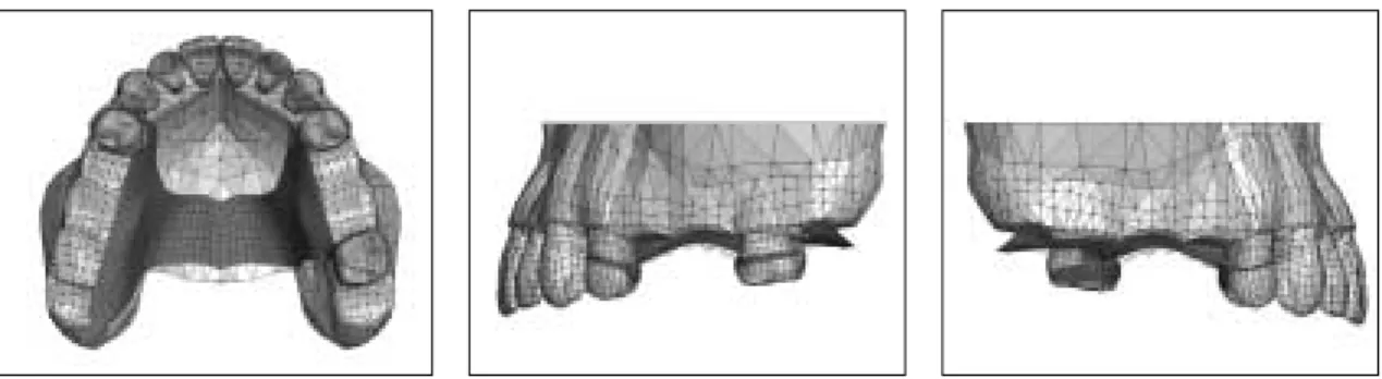
Kennedy Class II, modification 1 모양의 상악 부 분 무치악을 설정하고 여기에 적합되도록 국소의치 를 설계하였다. 결손치아의 위치는 우측 제 2 소구치 와 제 1, 2 대구치, 좌측 제 2 소구치 및 제 1 대구치 이며 구개판형(palatal strap) 주연결장치를 사용하였
치, 좌측 제 1 소구치, 좌측 제 2 대구치가 되도록 하 였다.(Fig. 1)
우측 제 1 소구치에는 유리단의 특성을 고려하여 직경 1.0 mm의 가공선 클래스프를 설계하였고, 좌 측 제 1 소구치에는 RPA 클래스프, 좌측 제 2 대구 치에는 전형적인 Aker’s 클래스프를 위치시켰 다.(Fig. 2)
각 지대치에는 해당 클래스프가 이상적으로 작용 하는데 필요한 20 게이지의 언더컷이 제공되도록 치 아의 외형을 조절하였고, 금속 재료의 물성에 따른 차이를 비교, 관찰하기 위하여 제 IV 형 금 합금, 코 발트-크롬(Co-Cr) 합금, 타이타늄 합금의 세 가지를 선정하여 유한요소 모형을 제작하였다.
Fig. 1. Design of partially edentulous dentition.
Fig. 2. Framework of removable partial denture.
2. 유한요소분석
본 연구에서 사용된 각 재료의 물성값은 Table I과 같다.
각각의 지대치에 설계된 클래스프별로 구분하여 응력을 구하였다. 클래스프의 유지선단부를 A, 클래 스프의 중앙부위를 B, 그리고 클래스프가 부연결장 치로부터 시작되는 부위를 C로 설정하여 각 부위에 서 발생하는 응력을 관찰하였다. 세 가지 금속 재료 와 세 가지 클래스프 형태에 따른 상호 비교를 함께 시행하였다.
치주인대의 두께는 0.2 mm,43) 피질골의 두께는 2.0 mm로 하였고, 해면골의 밀도는 해면골 내에서 균일한 것으로 설정하였다.
유한요소분석용 삼차원 모형의 제작에는 Hyp- ermesh(Altair Engineering Inc., Troy, MI, USA)를 사용하였고, 응력의 해석을 위해서는 PAM- CRASH 2G version 2003 (Sun Microsystems Inc., Santa Clara, CA, USA), 포스트 프로세싱을 위 해서는 PAM-VIEW version 2003(Sun Microsystems Inc., Santa Clara, CA, USA)을 이용하였다.
해석의 결과로서, 클래스프에 발생하는 대표 응력 인 von Mises 응력의 현상을 관찰하였다.
Ⅲ. 연구결과
1. Aker’s 클래스프에 발생된 응력 (Fig. 3 - 9)
1) 재료에 따른 응력 분석(Fig. 4�6)
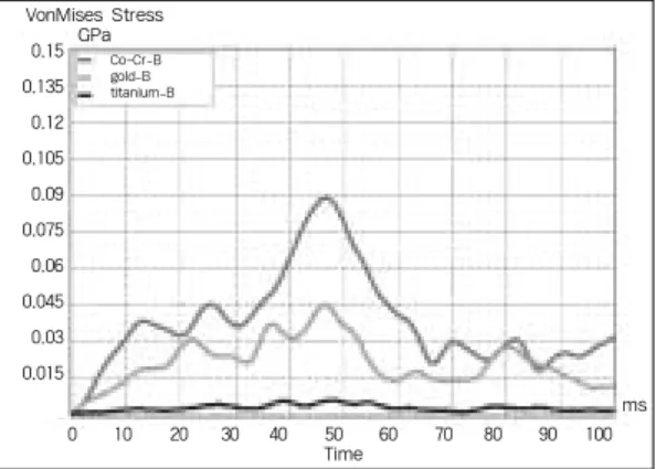
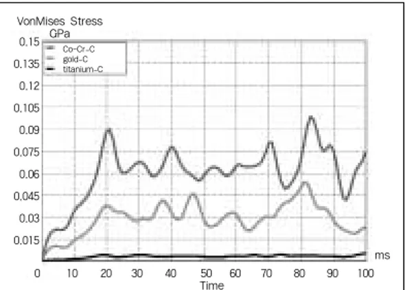
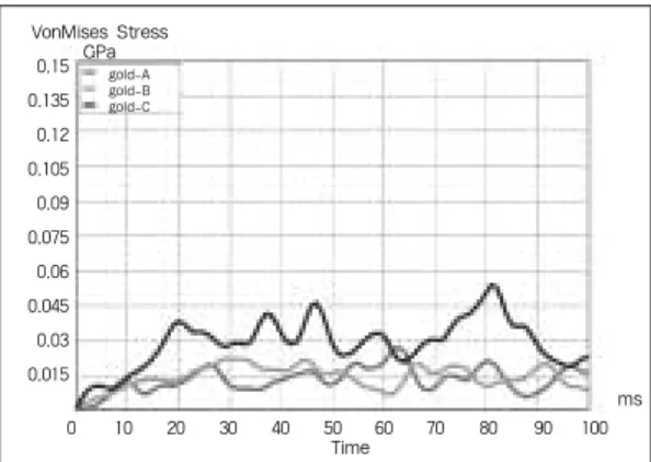
응력의 크기는 클래스프의 부위에 상관없이 코발 트-크롬 합금의 경우가 가장 크게 나타났으며, 그 다 음으로 제 IV 형 금 합금이었고, 타이타늄의 경우에 서 가장 작은 응력이 발생하였다. 부위별로는 부연 결장치 인접부에서 응력의 크기가 가장 작은 것으로 나타났으며, 유지선단부와 중앙부에서 높게 나타 났다.
2) 위치에 따른 응력 분석(Fig. 7�9)
사용한 금속의 종류에 따라 발생한 응력의 크기에 는 차이가 발생하였으나, 금속의 종류에 무관하게 치아로부터 클래스프가 이탈되기 시작하는 초반에 는 부연결장치 인접부(C)와 중앙부(B)에서 높은 응 력이 발생하였고, 이후에 유지선단부(A)에 높은 응 력이 발생하면서 클래스프가 완전히 지대치로부터 이탈하였다. 하지만, 타이타늄의 경우에서는 그 차이 가 매우 미미하였다.
Table I. Young’s modulus of elasticity and Poisson’s ratio42)
Material Young’s modulus(MPa) Poisson’s ratio(υ)
Type IV gold alloy 99300 0.30
Chrome-cobalt alloy 202000 0.33
c.p.* titanium 117000 0.33
Cortical bone 14700 0.30
Cancellous bone 1500 0.30
Dentin 18300 0.31
Enamel 84100 0.33
Periodontal ligament 1.18 0.45
* c.p. : commercially pure
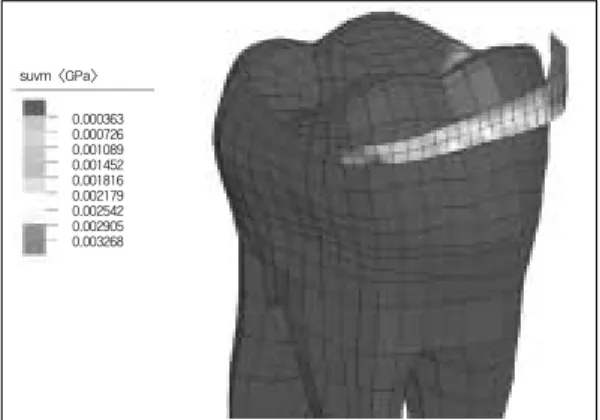
Fig. 3. Three-dimensional finite element model of Aker’s clasp on second molar.
(A: retentive tip, B: middle portion of clasp, C: minor connector area)
A B
C
Fig. 4. von Mises stress at point A.
Fig. 5. von Mises stress at point B. Fig. 6. von Mises stress at point C.
0 10 20 30 40 50 60 70 80 90 100
Time 0.15
0.135 0.12 0.105 0.09 0.075 0.06 0.045 0.03 0.015
ms
0 10 20 30 40 50 60 70 80 90 100
Time
ms
0 10 20 30 40 50 60 70 80 90 100
Time
ms
Co-Cr-A gold-A titanium-A
Co-Cr-B gold-B
titanium-B Co-Cr-C
gold-C titanium-C
0.15 0.135 0.12 0.105 0.09 0.075 0.06 0.045 0.03 0.015 VonMises Stress 0.15 GPa
0.135 0.12 0.105 0.09 0.075 0.06 0.045 0.03 0.015 VonMises Stress
GPa
Fig. 7a. Diagram of von Mises stress of Co-Cr alloy.
Fig. 7b. Graphic drawing of von Mises stress of Co-Cr alloy.
0 10 20 30 40 50 60 70 80 90 100
Time
ms
Co-Cr-A Co-Cr-B Co-Cr-C
0.15 0.135 0.12 0.105 0.09 0.075 0.06 0.045 0.03 0.015 VonMises Stress
GPa
suvm <GPa>
0.007529 0.0151 0.0226 0.0301 0.0376 0.0452 0.0527 0.0602 0.0678
2. RPA 클래스프에 발생된 응력 (Fig. 10 - 16)
1) 재료에 따른 응력 분석(Fig. 11�13)
RPA 클래스프의 경우에서도 코발트-크롬 합금, 제 IV 형 금 합금, 순수 타이타늄의 순서로 응력이 발생하였다. 응력값은 Aker’s 클래스프의 경우보다 다소 높았으며, Aker’s 클래스프의 경우와는 달리 중앙부에서 조금 낮았고, 유지선단부와 부연결장치 인접부의 응력은 Aker’s 클래스프의 경우보다 큰 값을 보였다.
2) 위치에 따른 응력 분석(Fig. 14�16)
대체로 Aker’s 클래스프와 유사한 양태를 보였으 나, 유지선단부의 응력이 상대적으로 높게 발생하였 다. 타이타늄도 마찬가지였지만, 응력의 절대값이 미미하여 뚜렷이 구분되지는 않는 소견을 보였다.
또한, Aker’s 클래스프의 경우에서는 부연결장치 인 접부와 중앙부에서 먼저 최대 유효응력이 발생한 후, 약간의 시간 간격을 두고 유지선단부에서 최대 유효응력이 나타났는데 반하여, RPA 클래스프에서 는 이러한 시간 차이가 그다지 크지 않았다.
Fig. 8a. Diagram of von Mises stress of type IV gold alloy.
Fig. 8b. Graphic drawing of von Mises stress of type IV gold alloy.
Fig. 9a. Diagram of von Mises stress of c.p.
titanium.
Fig. 9b. Graphic drawing of von Mises stress of c.p. titanium.
0 10 20 30 40 50 60 70 80 90 100
Time
ms
0 10 20 30 40 50 60 70 80 90 100
Time
ms
titanium-A titanium-B titanium-C gold-A gold-B gold-C
0.15 0.135 0.12 0.105 0.09 0.075 0.06 0.045 0.03 0.015 VonMises Stress
GPa
0.15 0.135 0.12 0.105 0.09 0.075 0.06 0.045 0.03 0.015 VonMises Stress
GPa
suvm <GPa>
0.002886 0.005773 0.008659 0.0115 0.0144 0.0173 0.0202 0.0231 0.026
suvm <GPa>
0.000363 0.000726 0.001089 0.001452 0.001816 0.002179 0.002542 0.002905 0.003268
Fig. 10. Three-dimensional finite element model of RPA clasp on premolar.
(A: retentive tip, B: middle portion of clasp, C: minor connector area)
A
B C
Fig. 11. von Mises stress at point A.
Fig. 12. von Mises stress at point B. Fig. 13. von Mises stress at point C.
ms
0 10 20 30 40 50 60 70 80 90 100
Time
ms ms
Co-Cr-A gold-A titanium-A
Co-Cr-C gold-C titanium-C Co-Cr-B
gold-B titanium-B
0.15 0.135 0.12 0.105 0.09 0.075 0.06 0.045 0.03 0.015
0.15 0.135 0.12 0.105 0.09 0.075 0.06 0.045 0.03 0.015 VonMises Stress
GPa
0 10 20 30 40 50 60 70 80 90 100
Time
0.15 0.135 0.12 0.105 0.09 0.075 0.06 0.045 0.03 0.015 VonMises Stress
GPa
0 10 20 30 40 50 60 70 80 90 100
Time
Fig. 14a. Diagram of von Mises stress of Co-Cr alloy.
Fig. 14b. Graphic drawing of von Mises stress of Co-Cr alloy.
ms
Co-Cr-A Co-Cr-B Co-Cr-C
0.15 0.135 0.12 0.105 0.09 0.075 0.06 0.045 0.03 0.015 VonMises Stress
GPa
0 10 20 30 40 50 60 70 80 90 100
Time
suvm <GPa>
0.004892 0.009783 0.0147 0.0196 0.0245 0.0293 0.0342 0.0391 0.044
3. 가공선 클래스프에 발생된 응력(Fig. 17 - 23)
1) 재료에 따른 응력 분석(Fig. 18�20)
가공선 클래스프에서는 유지선단부의 응력이 다른 부위보다 작게 나타났으며, 특히 유지선단부에서의 응력의 크기가 Aker’s 클래스프나, RPA 클래스프의 경우보다 눈에 띄게 작았다. 상대적으로 부연결장치 인접부에는 높은 응력이 발생함을 알 수 있었다.
2) 위치에 따른 응력 분석(Fig. 21�23)
코발트-크롬 가공선재의 경우, 유지선단부와 다른 부분간의 응력값 차이가 두드러지게 나타났으며, 금 합금에서도 코발트-크롬 합금에서와 같은 많은 차이 는 아니지만, 대체로 뚜렷한 차이를 보였다. 타이타 늄에서는 부위별 차이가 확연하지 않았다. Aker’s 및 RPA 클래스프에서 위치 B와 위치 C에서의 높은 응력 발생이 거의 동시에 먼저 발생한 모습을 보인 것에 비하여, 가공선 클래스프에서는 위치 B와 위치 C 간에도 시간 차이가 발생한 모양이 관찰되었다.
Fig. 15a. Diagram of von Mises stress of type IV gold alloy.
Fig. 15b. Graphic drawing of von Mises type IV gold alloy.
Fig. 16a. Diagram of von Mises stress of c.p.
titanium.
Fig. 16b. Graphic drawing of von Mises stress of c.p. titanium.
ms
0 10 20 30 40 50 60 70 80 90 100
Time
ms
titanium-A titanium-B titanium-C gold-A gold-B gold-C
0.15 0.135 0.12 0.105 0.09 0.075 0.06 0.045 0.03 0.015
VonMises Stress GPa
0 10 20 30 40 50 60 70 80 90 100
Time
0.15 0.135 0.12 0.105 0.09 0.075 0.06 0.045 0.03 0.015 VonMises Stress
GPa
suvm <GPa>
0.002508 0.005017 0.007525 0.01 0.0125 0.015 0.0176 0.0201 0.0226
suvm <GPa>
0.000275 0.000549 0.000824 0.001098 0.001373 0.001648 0.001922 0.002197 0.002471
Fig. 17. Three-dimensional finite element model of wrought wire clasp on premolar.
(A: retentive tip, B: middle portion of clasp, C: minor connector area)
A
B C
Base
Fig. 18. von Mises stress at point A.
Fig. 19. von Mises stress at point B.
Co-Cr-A gold-A titanium-A
Co-Cr-B gold-B titanium-B
0.15 0.135 0.12 0.105 0.09 0.075 0.06 0.045 0.03 0.015
0.15 0.135 0.12 0.105 0.09 0.075 0.06 0.045 0.03 0.015
VonMises Stress GPa
0 10 20 30 40 50 60 70 80 90 100
Time
ms
0 10 20 30 40 50 60 70 80 90 100
Time
ms
Fig. 20. von Mises stress at point C.
Co-Cr-C gold-C titanium-C
0.15 0.135 0.12 0.105 0.09 0.075 0.06 0.045 0.03 0.015
VonMises Stress GPa
0 10 20 30 40 50 60 70 80 90 100
Time
ms
Fig. 21a. Diagram of von Mises stress of Co-Cr alloy.
Fig. 21b. Graphic drawing of von Mises stress of Co-Cr alloy.
ms
Co-Cr-A Co-Cr-B Co-Cr-C
0.15 0.135 0.12 0.105 0.09 0.075 0.06 0.045 0.03 0.015 VonMises Stress
GPa
0 10 20 30 40 50 60 70 80 90 100
Time
suvm <GPa>
0.007788 0.0156 0.0234 0.0312 0.0389 0.0467 0.0545 0.0623 0.0701
Fig. 22a. Diagram of von Mises stress of type IV gold alloy.
Fig. 22b. Graphic drawing of von Mises type IV gold alloy.
Fig. 23a. Diagram of von Mises stress of c.p.
titanium.
Fig. 23b. Graphic drawing of von Mises stress of c.p. titanium.
ms
ms
titanium-A titanium-B titanium-C gold-A gold-B gold-C
0.15 0.135 0.12 0.105 0.09 0.075 0.06 0.045 0.03 0.015 VonMises Stress
GPa
0.15 0.135 0.12 0.105 0.09 0.075 0.06 0.045 0.03 0.015 VonMises Stress
GPa
0 10 20 30 40 50 60 70 80 90 100
Time
0 10 20 30 40 50 60 70 80 90 100
Time
suvm <GPa>
0.008044 0.0161 0.0241 0.0322 0.0402 0.0483 0.0563 0.0644 0.0724
suvm <GPa>
0.00053 0.001059 0.001589 0.002118 0.002648 0.003178 0.003707 0.004237 0.004766
Ⅳ. 총괄 및 고안
본 연구는 지대치에 위치하는 직접유지장치인 클 래스프가 착탈시에 발생하는 응력을 관찰하는 데 있 어, 클래스프의 기하학적 형태와 금속 재료의 종류 에 따른 차이를 관찰하기 위한 것이다. 모든 경우에 서 응력의 크기는 코발트-크롬 합금의 경우가 가장 크게 나타났으며, 그 다음으로 제 IV 형 금 합금이었 고, 타이타늄의 경우에서 가장 작은 응력이 발생하 였다. 타이타늄에 관한 연구에서 다소의 논란은 있 지만, 타이타늄 클래스프에서 코발트-크롬 합금 클 래스프보다 더 적은 유지력으로 기능할 수 있으며,
한 바 있다.44)이것은 본 연구에서 확인된 바, 최소의 응력이 작용된다는 사실과 무관하지 않다고 하겠다.
Aker’s 클래스프의 부연결장치 인접부에서 가장 작 은 응력을 받은 것은 부연결장치가 지대치의 유도면 을 따라 평행하게 이동하면서 단순한 마찰력만 받은 때문이다. 또, 클래스프가 서베이 라인을 지나면서 전체적으로 클래스프의 변위가 발생하여 마치 클래 스프가 협측으로 펴지는 듯한 힘을 받고 이 응력이 중앙부를 향하여 점점 전달되는 현상이 발생한다.
한편, 클래스프의 이탈에 따라 부위별로 최대 유효 응력이 나타나는 시기의 차이를 보이는 것은 서베이 라인 하방의 첨와(undercut)에 있던 유지선단부가
구치의 Aker’s 클래스프에서 두드러지게 나타났고, 작은 소구치의 RPA 클래스프는 상대적으로 그 차이 가 적었다. 타이타늄의 경우에서는 발생한 응력의 크기 자체가 작으므로 부위별 응력 발생 시간 차이 도 역시 미미하였다. RPA 클래스프의 경우에서 응 력값이 Aker’s 클래스프의 경우보다 다소 높았는 데, 이것은 기하학적으로 클래스프의 길이, 테이퍼 (taper) 정도, 테이퍼에 따른 두께의 변화 정도 등 기 하학적 요인이 Aker’s 클래스프보다 다소 불리한 때문이다.45) 가공선 클래스프에서는 유지선단부의 응력이 다른 부위보다 작게 나타났고, 특히 Aker’s, RPA 클래스프의 경우보다 눈에 띄게 작았다. 왜냐 하면, 상대적으로 부연결장치 인접부에는 높은 응력 이 발생하였는데, 가공선의 구조와 강도 측면에서 외력이 발생한 것을 응력으로 전환하기 보다는 변위 로 전환하기 때문이다. 설계된 모형에서, 레스트가 생략되어 있는데, 레스트는 근본적으로 교합압과 같 은 조직방향의 힘에 대한 저항, 즉 지지를 감당하는 역할을 하는 구조로서 지대치로부터 클래스프가 착 탈되는 유지력과는 무관하다. 본 연구를 위한 예비 실험에서 확인한 바에서도, 레스트는 지대치 및 클 래스프의 응력이나 변위와는 전혀 무관하였으므로, 시각적 편의를 위하여 레스트를 생략한 채로 도식화 하였다. 클래스프에 나타난 응력의 크기에 비하여 지대치에 발생한 응력은 상대적으로 매우 작았다.
이것은 치주조직이 건강한 지대치를 설계한 까닭으 로, 충분한 치조골의 지지를 받고 있는 지대치는 적 절히 설계된 클래스프의 반복적인 착탈에 충분히 건 강하게 견딜 수 있다는 것을 의미한다. 그러므로, 치 주조직의 건강도만 유지된다면 치관외 유지장치인 클래스프를 직접유지장치로 사용하여도 그 지대치 의 동요도 증가 등, 수명에 영향을 미칠만한 일은 발 생하지 않는다. 임상적으로 지대치의 수명에 해로운 결과가 초래되는 것은 서베이 라인의 잘못된 설정이 나 잘못된 클래스프 설계로 인해 측방압이 생리적인 한계를 넘거나 또는 구강위생관리의 소홀로 인해 발 생한 치주질환 등, 국소의치 설계 외적인 요인도 고 려해볼 만하다. 하지만, 유리단 국소의치에서는 의치 상과 잔존 치조제간의 긴밀한 접촉이 이루어지지 않 아서 의치상으로부터 회전력이 가해지는 경우에 지 대치에 위험이 발생할 수 있다.1-5,11-14)
나타나는 응력 현상을 관찰하는데 주안점을 두었다.
그러나, 실제 많은 임상 증례의 경우에서, 지대치 두 개 이상을 서로 연결하여 보강할 수도 있다. 지대치 를 연결하면 지대치의 동요도는 현격하게 감소하여 안정화되므로 더욱 바람직한 결과를 가져올 것으로 예측된다.46) 전체적인 연구결과를 토대로 클래스프 의 종류별로 응력의 크기를 비교해 보면, 길이가 짧 고 강성이 높은 RPA 클래스프에서 가장 높은 수준 의 응력이 발생한 것을 알 수 있었으며, 그 다음으로 Aker’s 클래스프와 가공선 클래스프의 순서로 나타 났다. 그러나, 부연결장치와 인접한 부위인 C 점에 서는 가공선 클래스프에서의 응력이 Aker’s 클래스 프보다 조금 더 크게 나타났다. 이것은 대구치에 형 성된 뚜렷한 유도면을 따라 Aker’s 클래스프가 착탈 되는 데 비하여 가공선 클래스프에서는 상대적으로 좁고 뚜렷하지 않은 유도면을 따라 클래스프가 이동 하면서 응력을 조금 더 받은 때문이라고 생각한다.
Ⅴ. 결 론
국소의치에 장착되는 직접유지장치인 클래스프가 지대치로부터 착탈될 때 발생하는 응력을 알아보기 위하여 Kennedy Class II, modification 1 상악 부분 무치악을 설계하고 국소의치 구조물을 설계한 후, 삼차원 유한요소분석법을 통하여 코발트-크롬 합금, 제 IV형 금 합금, 순수 타이타늄으로 된 Aker’s, RPA 및 가공선 클래스프에 관한 비선형, 동적 해석 연구를 하여 다음과 같은 결과를 얻었다.
1. 응력의 크기는 클래스프의 종류에 상관없이 코발 트-크롬 합금에서 가장 컸고, 타이타늄의 경우에 서 가장 작았다.
2. 첨와로부터 유지선단부가 빠져나오는 데 걸리는 시간 동안에는 응력은 받지 않으며, 이 시간 차이 는 RPA 클래스프가 Aker’s 클래스프보다 작았 다. 따라서, RPA 클래스프는 Aker’s 클래스프보 다 응력 및 변위의 부위별 차이가 작았다.
3. 가공선 클래스프의 유지선단부의 응력은 다른 클 래스프보다 훨씬 작았다.
4. 응력은 일반적으로 RPA 클래스프에서 가장 컸고 가공선 클래스프에서 가장 작았다.
참고문헌
1. Plotnick IJ, Beresin VE, Simkins AB.
The effects of variations in the opposing den- tition on changes in the partially edentulous mandible. Part III. Tooth mobility and chew- ing efficiency with various maxillary den- titions. J Prosthet Dent 1975;33:529- 34.
2. Bergman B. Periodontal reactions related to removable partial dentures: a literature review. J Prosthet Dent 1987;58:454-8.
3. Kern M, Wagner B. Periodontal findings in patients 10 years after insertion of re- movable partial dentures. J Oral Rehabil 2001;28:991-7.
4. Petridis H, Hempton TJ. Periodontal considerations in removable partial denture treatment: a review of the literature. Int J Prosthodont 2001;14:164-72.
5. Zlataric DK, Celebic A, Valentic-Peruzovic M. The effect of removable partial dentures on periodontal health of abutment and non- abutment teeth. J Periodontol 2002;73:137- 44.
6. Holmes JB. Influence of impression pro- cedures and occlusal loading on partial den- ture movement. J Prosthet Dent 1965;
15:474-83.
7. Leupold RJ, Kratochvil FJ. An altered cast procedure to improve tissue support for re- movable dentures. J Prosthet Dent 1965;
15:672-8.
8. Bickley RW. Combined splint-stress break- er removable partial denture. J Prosthet Dent 1969;21:509-12.
9. Levin B. Stressbreaker’s: A practical ap- proach. Dent Clin North Am 1979;23:77- 86.
10. Zinner ID. A modification of the Thompson
partial dentures. J Prosthet Dent 1989;
61:374-8.
11. Cecconi BT, Asgar K, Dootz E. Fit of the removable partial denture base and its ef- fect on abutment tooth movement. J Prosthet Dent 1971;25:515-9.
12. Maxfield JB, Nicholls JI, Smith DE. The measurement of force transmitted to abut- ment teeth of removable partial dentures.
J Prosthet Dent 1979;41:134-42.
13. Lee RE : Mucostatics. Dent Clin North Am 1980;24:81-96.
14. Taylor DT, Pflughoeft FA, McGivney GP.
Effect of two clasping assemblies on arch integrity as modified by base adaptation.
J Prosthet Dent 1982;47:120-5.
15. Kratochvil FJ, Caputo AA. Photoelastic analysis of pressure on teeth and bone sup- porting removable partial dentures. J Prosthet Dent 1974;32:52-61.
16. Eick JD, Browning JD, Stewart CD, McGarrah HE. Abutment tooth move- ment related to fit of a removable partial denture. J Prosthet Dent 1987;57:66- 72.
17. Shohet H. Relative magnitudes of stress on abutment teeth with different retainers. J Prosthet Dent 1969;21:267-82.
18. Clayton JA, Jaslow C. A measurement of clasp forces on teeth. J Prosthet Dent 1971;25:21-43.
19. Kotowicz WE, Fisher RL, Reed RA, Jaslow C. The combination clasp and the distal ex- tension removable partial denture. Dent Clin North Am 1973;17:651-60.
20. Krol AJ. Clasp design for extension base removable partial dentures. J Prosthet Dent 1973;29:408-15.
21. Thompson WD, Kratochvil FJ, Caputo AA. Evaluation of photoelastic stress pat-
tial dentures. J Prosthet Dent 1977;38:261- 73.
22. Beyron HL. Characteristics of functionally optimal occlusion and principles of oc- clusal rehabilitation. J Am Dent Assoc 1954;48:648-56.
23. Rad MN, Yarmand MA. Design of a direct retainer for removable partial dentures. J Prosthet Dent 1974;31:457-9.
24. Ben-Ur Z, Aviv I, Cardash HS. A modified direct retainer design for distal-exten- sion removable partial dentures. J Prosthet Dent 1988;60:342-4.
25. Aviv I, Ben-Ur Z, Cardash HS, Fatael H.
RLS-the lingually retained clasp assembly for distal extension removable partial dentures. Quintessence Int 1990;21:221-3.
26. Son HS, Kay KS. A photoelastic stress analysis in mandibular distal extension re- movable partial denture designed unilat- erally with different direct retainers. J Korean Acad Prosthodont 1992;30:25- 42.
27. Lee CH, Kim KN, Chang IT. Photoelastic stress analysis on the supporting tissue of mandibular distal extension removable partial denture with various design of direct retainers. J Korean Acad Prosthodont 1992;30:203-24.
28. Kim BM, Yoo KH. Three-dimensional photoelastic stress analysis of clasp retainers influenced by various designs on unilateral free-end removable partial dentures. J Korean Acad Prosthodont 1994;32:526-52.
29. Lee SH, Lee CH, Jo KH. Analysis of stress dveloped within the supporting tissue of abutment tooth with indirect retainer according to various designs of di- rect retainer and degree of bone resorption.
J Korean Acad Prosthodont 1998;36:150-
30. Jong YW, Jin TH. The effects of tooth mo- bility and design of direct retainer on the stress of supporting tissues in unilateral distal extension removable partial denture.
J Korean Acad Prosthodont 2000;38:59- 72.
31. Wu JC, Latta GH Jr, Wicks RA, Swords RL, Scarbecz M. In vitro deformation of acetyl resin and metal alloy removable par- tial denture direct retainers. J Prosthet Dent 2003;90:586-90.
32. Tebrock OC, Rohen RM, Fenster RK, Pelleu GB Jr. The effect of various clasp- ing systems on the mobility of abutment teeth for distal-extension removable partial dentures. J Prosthet Dent 1979;41:
511-6.
33. Browning JD, Jameson WE, Stewart CD, McGarrah HE, Eick JD. Effect of positional loading of three removable partial denture clasp assemblies on movement of abutment teeth. J Prosthet Dent 1986;55:347-51.
34. Igarashi Y, Ogata A, Kuroiwa A, Wang CH.
Stress distribution and abutment tooth mo- bility of distal-extension removable partial dentures with different retainers: an in vi- vo study. J Oral Rehabil 1999;26:111-6.
35. Craig RG, Farah JW. Stresses from load- ing distal-extension removable partial dentures. J Prosthet Dent 1978;39:
274-7.
36. Berg T, Caputo AA. Comparison of load transfer by maxillary distal extension re- movable partial dentures with a spring- loaded plunger attachment and I-bar re- tainer. J Prosthet Dent 1992;68:492-9.
37. Ogata K, Miyake T, Okunishi M.
Longitudinal study on occlusal force dis- tribution in lower distal-extension re- movable partial dentures with circum-
ferential clasps. J Oral Rehabil 1992;
19:585-94.
38. Hwang JW, Chang IT, Kim KN. Finite el- ement analysis of stress patterns on pe- riodontium of splinted abutments for dis- tal extension removable partial dentures.
J Korean Acad Prosthodont 1995;33:241- 68.
39. Kim KS, Kim KN, Chang IT. A three-di- mensional finite element stress analysis on the supporting tissues of removable par- tial dentures with various retainer designs.
J Korean Acad Prosthodont 1995;33:413- 39.
40. Shin SW, Ahn WJ, Jung YJ, Lee YS, Shim KS, Yoo KH. A three dimensional fi- nite element stress analysis on the force dis- tribution by distal extension partial den- tures employing attachments. J Korean Acad Prosthodont 1998;36:878-87.
41. Koak JY, Kim KN, Chang IT, Heo SJ. A study on the distribution of abutment
teeth and residual ridge area between telescopic and clasp type removable par- tial denture by finite element method. J Korean Acad Prosthodont 1999;37:104-26.
42. O’Brien WJ. Dental materials and their se- lection. 3rd ed. Carol Stream, 2002, Quintessence Publishing. pp 326-31,50.
43. Glickman I. Clinical periodontology.
Philadelphia, 1972, WB Saunders Co., pp 29, 329.
44. Vallittu PK, Kokkonen M. Deflection fatigue of cobalt-chromium, titanium, and gold al- loy cast denture clasp. J Prosthet Dent 1995;74:412-9.
45. Eliason CM. RPA clasp design for distal ex- tension removable partial dentures. J Prosthet Dent 1983;49:25-7.
46. Kratochvil FJ, Thompson WD, Caputo AA. Photoelastic analysis of stress patterns of teeth and bone with attachment retainers for removable partial dentures. J Prosthet
Reprint request to:
Seong-Joo Heo, D.D.S., M.S.D., Ph.D.
Department of Prosthodontics, College of Dentistry, Seoul National University 28 Yongun-Dong, Chongno-Gu, Seoul, 110-749, Korea
Statement of problem. In the partially edentulous patients, removable partial dentures have been working as a important treatment modality. Clasps, a kind of direct retainers, received some amount of stresses during the insertion and removal of partial denture on the abutment tooth.
Purpose. The study is to investigate stresses of the different clasps.
Material and methods. In order to investigate the degree of stresses, maxillary partial edentulism (Kennedy Class II, modification 1) was assumed and removable partial dentures were designed on it with three kinds of metallic materials; cobalt-chromium alloy, type IV gold alloy and com- mercially pure (c.p.) titanium. Aker’s clasp was applied on the left second molar, RPA (mesial rest-proximal plate-Aker’s) clasp was on the left first premolar and wrought wire clasp was on the right first premolar. Three dimensional, non-linear, dynamic finite element analysis method was run to solve this process.
Results.
1. Cobalt-chromium alloy had the highest von Mises stress value and c.p. titanium had the low- est one irrespective of the types of clasps.
2. In the Aker’s clasps, stress on the retentive tips was shown shortly after the appearance of stresses of the middle and minor connector areas. These time lag was much shorter in the RPA clasps than in the Aker’s clasp.
3. In general, retentive tips of wrought wire clasps had much less amount of stress than oth- er clasps.
Conclusion. The amount of stress was the highest in the RPA clasp and the lowest in the wrought wire clasp, in general.
STRESS ANALYSIS ON THE DIFFERENT CLASPS OF THE REMOVABLE PARTIAL DENTURE BY THREE-DIMENSIONAL FINITE ELEMENT METHOD
Hong-Ryul Park, D.D.S., M.S.D., Seong-Kyun Kim, D.D.S., M.S.D., Ph.D., Jai-Young Koak, D.D.S., M.S.D., Ph.D., Seong-Joo Heo, D.D.S., M.S.D., Ph.D.,
Ik-Tae Chang, D.D.S., M.S.D., Ph.D.
Department of Prosthodontics, College of Dentistry, Seoul National University
Key words : Clasp, Removable partial denture, Stress, Finite element analysis