• 검색 결과가 없습니다.

Computational Study of Supersonic Chevron Ejector Flows

N/A
N/A
Protected

Academic year: 2021

Share "Computational Study of Supersonic Chevron Ejector Flows"

Copied!
8
0
0

로드 중.... (전체 텍스트 보기)

전체 글

(1)

Research Paper DOI: http://dx.doi.org/10.6108/KSPE.2013.17.6.089

초음속 Chevron 이젝터 유동에 대한 수치해석적 연구

Fanshi Kong

a

․ 김희동

a, *

․ Yingzi Jin

b

Computational Study of Supersonic Chevron Ejector Flows

Fanshi Kong

a

․ Heuy Dong Kim

a, *

․ Yingzi Jin

b

a

School of Mechanical Engineering, Andong National University, South Korea

b

College of Mechanical Engineering & Automation, Zhejiang Sci-Tech University, China

*

Corresponding author. E-mail: [email protected]

ABSTRACT

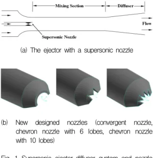
Considering the complexity and difficulty on the researching, how to enhance the performance of ejector-diffuser system effectively became a significant task. In the present study, the supersonic nozzle was redesigned using Chevrons installed at the inlet of the secondary stream of the ejector-diffuser system for the purpose of the performance improvement. A CFD method based on Fluent has been applied to simulate the supersonic flows and shock waves inside the ejector. Primary numerical analysis results show that the Chevrons get a positive effect on the ejector flows. The comparison of ejector performance with and without the Chevron was obtained and optimal number of chevron lobe is discussed to increase the performance. The ejector-diffuser system performance is discussed in terms of the entrainment ratio, pressure recovery as well as total pressure loss.

초 록

이젝터-디퓨저 시스템의 성능을 효과적으로 향상시키는 연구는 복잡성과 어려움을 고려하여 중요한 과제이다. 이 연구에서는, 성능 향상을 위해 이젝터-디퓨져 시스템의 이차유동 입구에 Chevron를 설치 하여 재설계하였다. 이젝터 내부의 초음속 유동과 충격파를 모사하기 위해 Fluent를 사용하여 수치해석 을 수행하였다. 주된 수치해석 결과로부터 Chevron은 이젝터 유동에 긍정적인 영향을 얻었다. 그리고 Chevron의 유무에 따라 이젝터 성능을 비교하였고, chevron의 최적 수는 성능 향상을 위해 설명하였 다. 이젝터-디퓨져 시스템의 성능은 유인비, 압력회복 뿐만 아니라 전압손실 관점에서 분석하였다.

Key Words: Ejector-Diffuser System(이젝터-디퓨저 시스템), Chevron Nozzle(Chevron 노즐), Shock Wave(충격파), Compressible Flow(압축성 유동), Supersonic Flow(초음속 유동)

Received 2 December 2012 / Revised 11 October 2013 / Accepted 20 October 2013 Copyright Ⓒ The Korean Society of Propulsion Engineers pISSN 1226-6027 / eISSN 2288-4548 / http://journal.kspe.org [이 논문은 한국추진공학회 2012년도 추계학술대회(2012. 11. 22-23, 여수 디오션리조트) 발표논문을 심사하여 수정 보완한 것임.]

1. Introduction

Supersonic ejector-diffuser system makes use

of primary stream with high speed and high

(2)

pressure to propel the secondary stream through pure shear action. It has many advantages over other fluid machinery such as no moving parts and no direct mechanical energy input. That's why ejector-diffuser system has been used in many engineering industrial applications such as air propulsion and ejector refrigeration. The ejector-diffuser system also can be considered as the most important device of the solar seawater desalination. Indeed, it can be used in many complex progresses as a compressor, a fluid transport component or a vacuum pump[1-3].

Along the development of solar industry, the ejector application in solar refrigeration and solar desalination was growing rapidly. At the same time, the ejector-diffuser system was increasingly considered as the most important equipment in these energy industries[4].

A fatal drawback of the ejector system is in its low efficiency. For many years, researchers have tried to describe the phenomena of ejector flow in order to achieve a high performance of ejector. Researchers got a lot of good results based on geometrical optimization, but the study of internal structure has got little attention[5]. In the Texas A&M University, a researching team put forward an optimal method with a mixing guide vane installed at the inlet of ejector[6].

A productive experimental work of this ejector has been made by Manohar, and Somsak W.

has finished the basic computational analysis in his doctoral dissertation[7-9]. Several new mixing guide vanes were installed and analyzed in [10]. The geometrical model they were used was widely applied in the solar desalination industrial. In the solar desalination process, the ejector-diffuser system can be used in reducing the pressure of evaporator and propelling incondensable gas into the

condenser.

In the present work, a new kind of nozzle with Chevrons was installed based on the supersonic ejector-diffuser system used in the Manohar and Somsak’s work[7-9]. A typical Chevron nozzle was illustrated in 3D graphics as showed in the Fig. 1 (b). Primary experiment was performed using convergent nozzle only, which was also used in the present numerical study. Actually, the nozzle with Chevrons was widely used in the aerospace science and aircraft engine. It has many advantages such as jet noise reduction, infra-red signature control and performance improvement of conventional converging- diverging nozzle or convergent nozzle[11]. D.

Thirumuthy et al. also observes that the nozzle features were improved as a result of installing the Chevrons[11]. In this paper, a numerical method based on Fluent has been applied to simulate supersonic flows and shock waves of the ejector internal flow.

Exactly same geometrical model was created to validate the results of experimental data. The

(a) The ejector with a supersonic nozzle

(b) New designed nozzles (convergent nozzle, chevron nozzle with 6 lobes, chevron nozzle with 10 lobes)

Fig. 1 Supersonic ejector-diffuser system and nozzle structures.

(3)

Chevron nozzle effects were compared with conventional convergent nozzle refers to the performance of ejector-diffuser system. CFD results were also compared between 6 and 10 lobes of Chevron nozzles.

2. Numerical Simulation

2.1 Computational flow model

The ejector-diffuser system was shown schematically in the Fig. 2. A three-dimensional axis-symmetric model was applied in the present works. The diameters of supersonic nozzle (D1), secondary stream inlet (D2), mixing section (DM) and ejector exit (DE) were kept constant as shown in Table 1. At the same time, length of the mixing chamber (LM) and diffuser (LD) were also fixed as mentioned in the table. These values were taken from experimental results to validate the simulation. As it shown, the supersonic nozzle is quite small compared to the ejector itself.

Actually this is an ejector called “high efficiency ejector” which was introduced in the former section.

The ejector-diffuser system installing a small nozzle get a good performance shows that the nozzle extent still plays an important role. Results of present study also agree with that.

In the present study, the supersonic nozzle was redesigned to study the Chevrons effects. It should be pointed out the diameter of supersonic nozzle was fixed, which means the Chevron nozzle and convergent nozzle have a same radius of inlet tube. At the same time, the minimum radius was different because the Chevron nozzle is a kind of extended version of convergent nozzle. Fig. 3 represents the half geometrical model of the nozzle with 10 Chevrons.

While r represents the radius of the primary inlet tube, and rN is the radius of convergent nozzle and also the base line position of Chevrons. Pointed shape makes the nozzle converge to a radius of rC. In this figure, 10 Chevrons were distributed averagely outside

the previous nozzle exit. The convergent nozzle geometry can be easily obtained using the figure 3 model without the Chevron lobes. For 6 Chevrons model, the values of rC, r and rN are exactly same to the 10 Chevrons model, only the Chevrons number is different.

2.2 Numerical Method

For the CFD software, ANSYS Fluent 14.0 was chosen to simulate steady internal flows of ejector.

Ideal gas was used as the working fluid in all cases.

A finite volume scheme and density-based solver with coupled scheme were applied in the computational process. SST k-ω turbulent model, implicit formulations were used considering the accuracy and stability.

Second-order upwind scheme was used for turbulent kinetic energy as well as spatial discretizations.

Gambit was used to build structural mesh. The mesh study was based on the ejector with convergent nozzle without chevron lobes. Boundary layer effects were considered by making finer grid densely clustered close to the walls. The first(coarse) grid with

Ejector-diffuser system Diameter of supersonic nozzle

D1 6.08 mm

Diameter of secondary stream inlet

D2 34.8 D1

Diameter of mixing section

DM 14D1

Diameter of ejector exit DE 34.8 D1 Length of mixing chamber LM 15DM Length of diffuser LD 12.7DM Table 1. Geometrical parameters used in simulations.

Fig. 2 Schematics of supersonic ejector-diffuser

system.

(4)

Fig. 3 Geometrical model of the nozzle with 10 Chevrons.

Fig. 4 Computational mesh of the numerical model.

y+ of about 4.6 has 156,527 cells. The second (medium) grid set has 232,325 cells with a y+ of about

2.7. The third (fine) set grid is generated using the same minimum space as the second set has 345,235 cells. The difference between CFD analysis and experimental results was less than 4%. The computational domain with 232,325 cells was chosen because of its less computational time and more accurate result, which has been shown in the Fig. 4.

Pressure inlet boundary condition was set at primary stream inlet of the ejector. computational pressures were taken as total values. The secondary inlet and outlet of ejector were extended to stabilize the computational results. Pressure outlet boundary conditions with 1 bar were used at both secondary inlet and outlet of the ejector. Therefore, the secondary stream inlet and ejector exit were taken from ambient conditions of an atmospheric pressure.

The total pressure at nozzle exit (P

t

) and

static pressure (P

s

) can be calculated isentropically to give the Mach number.

Related initial values can be calculated in these equations:

 

    

  

  

 

 

    

  

 

where,

P

s

: static pressure, Pa P

t

: total pressure, Pa γ: specific heat ratio

M: Mach number at nozzle exit T

s

: static temperature, K T

t

: total temperature, K

Mass flow rate (ṁ) is so important to compare with the experimental data. As one of the indispensable values to describe the ejector-diffuser system performance, the entrainment ratio (Rm) is also obtained from mass flow rate. Entrainment ratio is a ratio between the mass flow rate of secondary flow (ṁ

2

) and primary flow (ṁ

1

). The calculation method of these values can be represented by the following equations:

   Rm    

 

where,

ρ: density, kg/m

3

V: velocity, m/s A: area, m

2

ṁ: mass flow rate, kg/s

Pressure recovery (ΔP) can be defined as the

difference between static pressure at the

(5)

secondary stream inlet (P

s2

) and static pressure at the outlet of ejector-diffuser system (P

se

).

Sometimes, the pressure recovery coefficient (Δ P/P

d

) will be used as a non-dimensional value to describe it. In what the P

d

is defined as the dynamic pressure. In the subscripts, "e" means the ejector exit and "2" means secondary stream.

∆      

 

∆  



    

3. Results and Discussion

3.1 Supersonic nozzle flow field

Generally speaking, the flow field in the ejector-diffuser system is very difficult because the shock system is so complicate to be predicted. The flow turbulent mixing, compressibility effects and even flow unsteadiness are also the obstacles. The results from CFD analysis were quite clear for flow phenomenon to be discussed in detail, especially nearby the supersonic nozzle.

Chevrons effects were compared with convergent nozzle based on the data obtained from CFD analysis shown in these figures below. Fig. 5 and 6 present the axial distribution of Mach number and temperature around the nozzle exit extent. X-axis is defined as the axial distance along the flow direction, while D means the diameter of primary inlet tube. The flow fields with a convergent nozzle, 6 lobes Chevron nozzle and 10 lobes Chevron nozzle were compared to study the effects of Chevrons. With a same primary inlet pressure of about 10bar, the nozzle with Chevrons restricts shock

Fig. 5 Axial distribution of mach number under same inlet pressure (10 bar).

Fig. 6 Axial distribution of temperature under same inlet pressure (10 bar).

development and makes the shock system weaker after the first big shock. Furthermore, the shock strengthen was decreased under the Chevrons effect.

Even though the Chevrons shock strengthen

and type are totally different from the

convergent nozzle, the nozzle with 10

Chevrons and 6 Chevrons obtain similar

results in the axial distribution of Mach

number and temperature. An interesting

phenomenon is the Mach number distribution

become smoother after the first strong shock

using the Chevron nozzle. That also leads to

(6)

(a) Convergent nozzle

(b) Chevron nozzle

Fig. 7 Flow fields display around nozzle exit.

more energy saving and more mixing flows would be entrained. That’s because under the Chevrons influence, more longitudinal vortices were generated and the nozzle involve more secondary stream into the ejector. The mixing process was enhanced and more energy transfer between two streams would happen.

That’s why the shock wave became weak and smooth compare to the model with convergent nozzle. The chevron nozzle effects on ejector flow fields can be found in the Fig. 7.

3.2 Nozzle effects on ejector performance

From the previous section, the nozzle effects were discussed in sight of turbulent mixing and compressibility effects. The Chevrons influence on the shock structure will give an effect upon the ejector system surely. Fig. 8, 9 and 10 are the ejector performance comparisons among these three nozzles, discussed in terms of entrainment ratio, mass flow rate

and pressure recovery of the nozzle exit. Firstly, the CFD result of convergent nozzle entrainment ratio was compared with experimental data [7-9] in the Fig. 8.

According to agreement with experimental results, CFD analysis was validated among these 5 operating conditions, in terms of 9, 10, 11, 12, 13.

For the most important parameter, the entrainment ratio plays a really important role in the performance analysis, which has been shown in the Fig. 8. P1/P means the pressure ratio at the primary stream inlet.

represents different inlet boundary condition. Fig. 8 shows that the entrainment ratio was enhanced at least 14.8% under the influence of 10 Chevrons. For 6 Chevrons model, the entrainment ratio was also enhanced, but lowers than the 10 Chevrons model.

Better effects on ejector-diffuser were obtained under the Chevrons effects. This result can be analyzed as the Chevron effects on ejector internal flow, which has been discussed in 3.1 section. Generally speaking, a nozzle with Chevrons can involve more flow vortexes and more vertical flow was introduced into the stream. Therefore, rotary stream passed through the mixing chamber and introduced more shear stress to propel the secondary stream into the ejector-diffuser system, which effectively enhanced the performance of the ejector-diffuser system.

Mass flow rate comparison at nozzle exit using three nozzles was illustrated in the Fig. 9. The mass flow rates of nozzle exit were compared among three nozzles. Under the same pressure condition, the nozzles with Chevrons get a lower mass flow rate at the nozzle exit. With the installation of Chevrons outside the nozzle, more friction and resistance will be involved. Compared Fig. 8 and 9, it’s also can be found that Chevron nozzle obtains higher entrainment ratio than the convergent one, even with same mass flow rate at the primary stream inlet.

Pressure recovery is another indispensable value to

study the ejector-diffuser system performance. In

order to study the mass flow rate effects more

accurately, the pressure recovery comparison among

(7)

Fig. 8 Ejector performance comparison among three nozzles.

Fig. 9 Mass flow rate at nozzle exit using three nozzles.

Fig. 10 Pressure recovery comparison between three nozzles.

three nozzles was illustrated with same mass flow rates as shown in the Fig. 10. From this figure, higher pressure recovery was obtained under the 10 Chevrons effects, which means the secondary stream pressure was elevated to a higher level. The model with 6 Chevrons has no influence on the pressure recovery, and pressure coefficient even decreased at some low mass flow rate cases. This also can prove that chevron lobes have a positive influence on ejector while lobes number have no clear affect. For the nozzle with 10 Chevrons, the pressure recovery was increased 8.5% in average, and get a maximum value of 18.9 when it get the mass flow rate of 0.01 kg/s.

4. Conclusions

In the present paper, a computational method was carried to simulate the internal flow of an ejector-diffuser system. The Chevron nozzle effects on the performance of the ejector were investigated. Numerical results were confirmed by previous experimental data.

The numerical simulation results of nozzle with 0, 6 and 10 Chevrons have been compared. In the numerical analysis, the Chevron nozzle effect on shock system was obtained clearly. More longitudinal vortices were generated which involved more secondary stream. As the result of the updated model, the ejector with 10 Chevrons nozzle shows the better results: entrainment ratio was improved 14.8% in average, and the maximum 21.8%. At the same time, pressure recovery was increased 8.5% in average.

Further work is going on to optimize the supersonic ejector-diffuser system with Chevrons.

References

(8)

1. Aidoun, Z. and Ouzzane, M., "The Effect of Operating Condi-tions on the Performance of a Supersonic Ejector for Re-frigeration,"

International Journal of Refrigeration, Vol. 27, No. 8, pp. 974-984, 2004.

2. Bartosiewicz, Y., Aidoun, Z. and Mercadier, Y., "Numerical Assessment of Ejector Operation for Refrigeration Appli-cations Based on CFD," Applied Thermal Engineering, Vol. 26, No. 5-6, pp. 604-612, 2006.

3. Yan, J., Shao, S., Liu, J. and Zhang, Z.,

"Experiment and Analy-sis on Performance of Steam-Driven Jet Injector for Dis-trict-Heating System," Applied Thermal Engineering, Vol. 25, No. 8-9, pp. 1153-1167, 2005.

4. Chunnanond, K. and Aphornratana, S.,

"Ejectors: Applications in Refrigeration Technology," Renewable and Sustainable Energy Reviews, Vol. 8, No. 2, pp. 129-155, 2004.

5. Kandakure, M.T., Gaikar, V.G. and Patwardhan, A.W., "Hy-drodynamic Aspects of Ejectors," Chemical Engineering Science, Vol. 60, No. 22, pp. 6391-6402, 2005.

6. Holtzapple, M.T., "High-Efficiency Jet

Ejector," Invention Disclosure, Texas A&M University, 2001.

7. Vishwanathappa, M.D., "Desalination of Seawater using a High-Efficiency Jet Ejector," Master Thesis, Texas A&M University, 2005.

8. Watanawanavet, S., "Optimization of a High-Efficiency Jet Ejector by Computational Fluid Dynamics Software,"

Master Thesis, Texas A&M University, 2005.

9. Somsak, W., "CFD Optimization Study of High-Efficiency Jet Ejector," Doctoral Dissertation, Texas A&M University, 2008.

10. Kong, F.S., Kim, H.D., Jin, Y.Z. and Setoguchi, T., "Computational Analysis of Mixing Guide Vane Effects on Performance of the Supersonic Ejector-Diffuser System,"

Open Journal of Fluid Dynamics, Vol. 2, pp.

45-55, 2012.

11. Thirumurthy, D., Gregory, A.B., Anastasios

S.L. and John, P.S., "Preliminary Design

and Computational Analysis of an Ejector

Nozzle with Chevrons," 49th AIAA

Aerospace Sciences Meeting including the New

Horizons Forum and Aerospace Exposition,

Orlando, Florida, 2011.

수치

Fig.  1  Supersonic  ejector-diffuser  system  and  nozzle  structures.
Fig.  2  Schematics  of  supersonic  ejector-diffuser  system.
Fig.  5  Axial  distribution  of  mach  number  under  same    inlet  pressure  (10  bar).
Fig.  7  Flow  fields  display  around  nozzle  exit.
+2

참조

관련 문서