A Study of the Transient Flow Characteristics of a Vacuum Ejector- Diffuser System.
G. Rajesh
†, H. D. Kim
*진공 이젝터-디퓨져 시스템의 일시적 유동특성에 관한 연구
G. Rajesh
†· 김희동*Key Words : Ejector (이젝터), Transient flow (일시적인 유동), Primary jet(주제트), Entrainment(혼 입), Vacuum(진공)
Abstract
In vacuum ejector-diffuser systems where a finite volume secondary chamber is used, the secondary jet exhibits transient characteristics during start-up. A steady state is achieved after some time in which mass entrainment prevails indefinitely inside the ejector, though there is no flow from the secondary chamber. An attempt is made in this work to study the infinite entrainment of secondary jet into the primary jet from a finite secondary chamber, with the help of a computational fluid dynamics method. The present study is also intended to identify the operating range of vacuum ejector-diffuser systems where the steady flow assumption can be applied without uncertainty. The results obtained show that the only condition in which an infinite mass entrainment is possible is the generation of a re-circulation zone near the primary nozzle exit. The flow in the secondary chamber attains a state of dynamic equilibrium at this point. Steady flow assumption is valid only after this point.
Nomenclature
m
• = mass flow rate, kg/s p = pressure, Pat = time, s Subscripts p = primary flow s = secondary flow 0 = initial/total condition
1. Introduction
Ejector is a simple device which can transport a
low-pressure secondary flow by using a high-pressure primary flow. In general, it consists of a primary driving nozzle, a mixing section, and a diffuser (1). The ejector system entrains the secondary flow through a shear action generated by the primary jet. The efficiency of such an ejector system is relatively very low, compared to other fluid transport devices driven mainly by normal forces (2). However, its major advantage is in a simple structure with no moving parts, and it can not only compress and transport a large amount of fluid with a small driving energy, but needs little maintenance. For these reasons, the ejector system has been extensively utilized for the thrust augmentation of V/STOL (3, 4), high-altitude simulation facility5, combustion facility6, refrigeration system (7), natural gas generation(8), fuel cells (9, 10), noise-control facility (11), etc.
The ejector systems can be largely classified into three major categories depending on its functions, such as a compressor, a fluid transport device and a vacuum
†Doctoral Student, School of Mechanical Engineering, Andong National University
*Professor, School of Mechanical Engineering, Andong National University, E-mail: [email protected]
TEL: (054) 820-5622, FAX: (054) 820-6127
pump. In a compressor system, the ejector compresses the secondary low-pressure stream in the mixing chamber using primary high-pressure stream. The ejector facilitates the dragging and carrying the secondary stream along with the primary stream when it is employed for fluid transportation. Often it is used to create a certain vacuum level in the secondary chamber, such as those required in high-altitude simulation tests. This is done by dragging mass flow from a finite secondary chamber.
Until now, a large number of researches have been made to design and evaluate the ejector systems. In all these works, it is assumed that the ejector system has an infinite secondary chamber which can supply mass infinitely. Thus steady flow assumption has been successfully applied for the purpose of design or performance analysis of the ejector system. However, in almost all of the practical applications, the ejector system has a finite secondary chamber. There is always a finite mass to be dragged into the primary stream inside the ejector, regardless of the situations in which they are being used. This implies that steady flow can be possible only after the flow inside the secondary chamber has reached an equilibrium state. To the author’s best knowledge, there are no reports on the transient characteristics of the ejector system which has a finite secondary chamber. None of the works to date discloses the detailed flow process until the secondary chamber flow reaches an equilibrium state, and what happens at the equilibrium state has been beyond the interest.
The objective of the present study is to investigate the transient flow through the ejector system. An attempt is made to investigate the interesting and conflicting phenomenon of the infinite entrainment of secondary stream into the primary stream from a finite secondary chamber. The present study is also intended to identify the operating range of vacuum ejector-diffuser systems where the steady flow assumption can be applied without uncertainty, with the help of a computational fluid dynamics method.
The results obtained show that the one and only condition in which an infinite mass entrainment is possible in such types of ejectors is the generation of a re-circulation zone near the primary nozzle exit. The flow in the secondary chamber attains a state of dynamic equilibrium at this point. A steady flow assumption is valid only after this point.
2. Computational Methodology
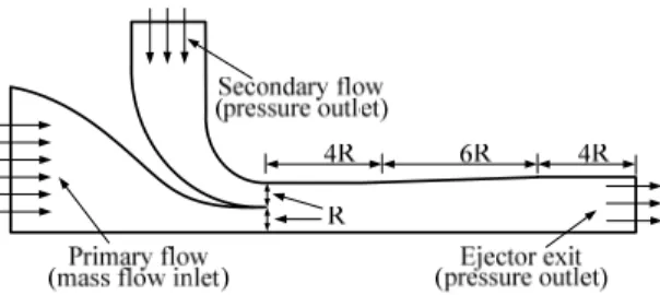
The schematic and boundary conditions of theFig. 1 Schematic of ejector system
ejector system are shown in Fig.1. It consists of a primary driving device, a constant volume secondary chamber, a constant area mixing section and a diverging section and exit which act as the diffuser.
The primary driving device is a sonic nozzle. When the primary flow starts, fluid is dragged from the secondary chamber and mixed with the primary flow in the mixing section of the ejector. The mixed flow is compressed in the diffuser and is discharged from the exit of the ejector diffuser.
Commercial software Fluent 6 is used to analyze the transient flow field. 2-D axi-symmetric solver is chosen with coupled implicit solver for both steady and unsteady simulations. The working gas is selected to be hydrogen. The grid system consisted of structured quadrilateral cells. A study for checking the grid independence was also performed with steady solver, based on the maximum Mach number inside the ejector and the optimum number of grid points arrived at was 33500. Standard k-ε model was used in the computations.
Initially, steady flow has been simulated with mass flow inlet boundary condition (0.0008kg/s) at the primary nozzle inlet and pressure outlet conditions at secondary nozzle inlet (1.26bar) and the ejector exit (1.32bar). Static pressure inside the secondary chamber has been monitored. Convergence is also monitored based on both static pressure history and residuals.
After the simulation has achieved convergence, the secondary flow inlet condition has been changed from pressure outlet to wall boundary condition in order to have a fixed volume secondary chamber, and correspondingly the solver is switched to unsteady one with a time step size of 10-7s.
3. Results and discussion
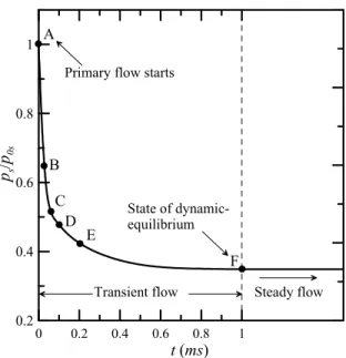
Fig.2 shows the static pressure history in the secondary chamber for the unsteady simulations. The term ps/p0s refers to the static pressure normalized by
0.2 0.4 0.6 0.8 1
ps/p0s
0 0.2 0.4 0.6 0.8 1
t (ms)
Transient flow Steady flow A
B C
D E
F Primary flow starts
State of dynamic- equilibrium
Fig. 2 Schematic of ejector system
the initial pressure p0s in the secondary chamber. Point A refers to the state on the verge of the instant at which the primary flow is started.
Figs.3 shows the mass flow history from the
secondary chamber, where ω =
( m
• p− m
•s) / m
• p. It can be noted that the flow reaches pressure equilibrium at point F in Fig.2, corresponding to the flow state at which the secondary mass flow is zero in Fig.3 at the same time instant (1.002ms). The unsteady0.2 0.4 0.6 0.8 1
ω
0 0.2 0.4 0.6 0.8 1
t (ms) Transient flow
Steady flow State of dynamic equilibrium
Fig. 3 Construction of chimera meshes for piston
flow quickly attains pressure equilibrium between the secondary chamber and the primary nozzle exit, owing to the small volume of the secondary chamber. It should be noted that at point F in Fig.2, though there is no pressure difference between the secondary chamber and the mixing section of the ejector, the flow field is not frozen. The fluid is still dynamic inside the ejector and hence the point F is termed as “state of dynamic equilibrium.”
Flow field at the start of the primary flow, denoted by point A in Fig.2, is detailed in Figs.4 and 5, which show the density contours and velocity vectors in the vicinity of the primary nozzle exit. The velocity vectors show how the fluid from the secondary jet is dragged due to the shear action generated by the primary jet.
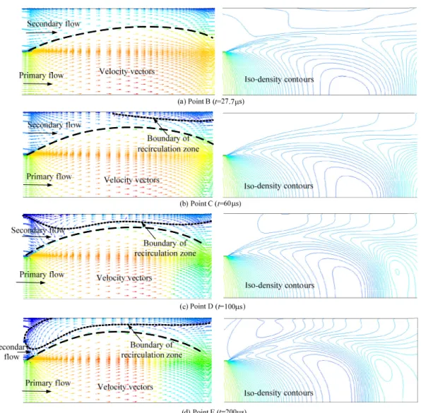
In order to understand how flow achieves this dynamic equilibrium state, flow states correspond to different time instants, indicated as B, C, D and E are illustrated in Fig.6 where the respective velocity vectors and iso-density contours are shown.
Consequent on the reduction in the secondary chamber pressure, the primary jet keeps on expanding.
Velocity vectors corresponding to the point B in Fig.6(a) show a more expanded jet compared to that at point A because of the reduction of secondary chamber pressure. Fig.6(b) reveals a small re-circulation zone
Fig. 4 Iso-density contours (point A)
Fig. 5 Computational conditions for piston motion
Fig. 6 Flow fields at various time instants downstream of the first Mach disc of the primary jet, at
point C (t=60μs). The area of re-circulation zone increases with the reduction in secondary chamber pressure as seen from the velocity vectors at point D (t=100μs) in Fig.6(c) It is also noticed from the flow state at point E in Fig.6(d), that the re-circulation zone is moving upstream with the secondary chamber pressure reduction.
Fig.7 shows the velocity vectors in the vicinity of the primary nozzle exit at point F where the flow has reached the pressure equilibrium. It is seen that the re- circulation zone has sufficiently moved upstream and the fluid particles are turning 180o in order to have themselves entrained into the shear layer. This is the one and only condition in which the two conflicting flow conditions can be possible in a real flow situation.
The conflicting conditions are the finite mass supply from the secondary chamber and the infinite mass entrainment into the shear layer as long as primary flow is present. It is worth noting that, though the fluid in the secondary chamber is stagnant, the fluid in the mixing section of the ejector is still dynamic, owing to the re-circulation. The re-circulation zone appears in the flow field at a particular time instant. In order to make it clear how the re-circulation zone is generated inside the ejector, the wall shear stress along the ejector wall is plotted at various time instants in Fig.8.
It can be seen that the first time instant at which the re-circulation zone appears in the flow field is around 40μs after the primary flow is started. Here, the wall shear stress is negative in the divergent portion of the nozzle. From this point onwards, the magnitude of
Primary flow
Entrainment begins
Iso-density contours
Fig. 7 Detailed flow field in the vicinity of primary nozzle exit at the state of equilibrium (Point F) the negative wall shear stress is increasing with its
-800 -400 0 400 800
Wall shear stress (Pa)
Mixing section (constant area)
27.7μs 40.4μs
46.5μs
80μs60μs 100μs
t=200μs
Outlet section (constant area) t=0
Divergent section Distance
Fig. 8 Distribution of wall shear stress along the ejector wall
peak moving upstream. This is in correlation with what has been observed early in the velocity vectors. The re- circulation zone is moving upstream with reducing secondary chamber pressure.
In the unsteady case, the pressure in the secondary chamber is continuously reduced due to a fixed chamber volume. As the secondary chamber pressure reduces with time, the primary jet characteristics are changed as it is expanded more and more. This makes a hypothetical convergent section (shown by dotted line in Fig.5) more converged as the primary jet develops in the radial direction. The flow in this area is still subsonic, consequently leading to more reduction in the secondary flow pressure as it moves along the primary jet through the converging section.
The entrained flow being subsonic has to increase its velocity as it passes through the converging section.
During this time, the expansion process of the primary jet continues and Mach disk becomes stronger downstream, and correspondingly, the pressure increases downstream of the minimum area of the hypothetical nozzle section. The flow has now to travel against a high adverse pressure gradient and the available kinetic energy of the entrained flow at this location is too small to overcome this pressure hill.
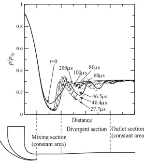
This causes the flow to separate and re-circulate in this location. This can clearly be understood from Fig.9 where the ratio of the static pressure normalized by total pressure of the primary flow along the ejector axis
0 0.2 0.4 0.6 0.8 1
p/p0p
Mixing section (constant area)
Divergent section Outlet section (constant area) t=0
27.7μs40.4μs46.5μs 60μs 100μs80μs 200μs
Distance
Fig. 9 Static pressure distribution along the ejector axis
is shown for various time instants.
It is seen that the second Mach disk is traveling upstream with increasing time and decreasing secondary chamber pressure. The re-circulation zone also follows the same trend. This implies that the effect of first Mach disc does not come into play during the initial stages of the generation of the re-circulation zone. After the re-circulation zone is expanded enough, the location of maximum wall shear stress is controlled by the first Mach disc as seen from Figs. 8 and 9.
The present analysis reveals that starting process of an ejector vacuum system with constant area secondary chamber is inherently conflicting and complicated due to transient flow structures. Even under the condition of a finite mass supply, dynamic effects persist under equilibrium conditions. The flow achieves this state through the generation of a re- circulation zone inside the ejector which is the only condition for the flow to achieve a dynamic equilibrium state inside the ejector. For such systems, where the ejector is used as a vacuum pump, the required level of vacuum can be maintained in the vacuum tank after a particular time instant, while the entrainment takes place inside the ejector for infinite time, as long as primary flow is present.
4. Conclusions
The present study on the transient features of the starting process of the ejector system with a finite secondary chamber reveals interesting flow phenomena.
The flow field exhibits significant changes from that of a steady ejector system which has an infinite secondary chamber. The flow through the ejector attains a dynamic equilibrium state after a particular time depending on the secondary chamber volume.
At the equilibrium state, a re-circulation zone appears in the vicinity of the primary nozzle exit. Due to this re-circulation zone, continuous mass entrainment into the primary jet prevails even when there is no flow from the secondary chamber. This is the one and only condition for the two conflicting phenomena to occur simultaneously, i.e., the finite mass flow from the secondary chamber and infinite mass entrainment into the primary jet. Moreover, during the transient period of the ejector flow, the primary jet characteristics are continuously changing owing to the reduction in pressure at the outlet of the primary nozzle. This will have a deterministic effect on
the whole flow field. The present analysis thus permits to identify how the flow field behaves with respect to the transient changes during the starting process of ejector systems.
References
[1] Keenan, J. H., Neumann, E. P. and Lustwek, F., “An Investigation of Ejector Design by Analysis and Experiment,” Journal of Applied Mechanics, Vol.17, No.3, 1950.
[2] Kim, H. D. and Lee, Y. K., “Numerical Simulation of the Supersonic Flows in the Second Throat Ejector-Diffuser Systems, Journal of Thermal Science, Vol.8, No.4, 1999.
[3] Whittley, D. C., “Ejector-Powered Lift Systems for V/STOL,” NASA-1974-0063487, 1974.
[4] Seiler, M. R. and Schum, E. F., “Analytical and Experimental Investigation of Diffusers for V/STOL Thrust-Augmenting Ejectors,” AIAA Journal, Vol.16, No.10, 1979.
[5] Mandell, B., Mc Farland, B. L., Nelson, R. E.
and PATMOR, G. O., “Scale Model Testing of 90 deg Supersonic Turn Ejector Systems for Altitude Simulation,” Journal of Spacecraft and Rockets, Vol.1, No.1, 1964.
[6] Chen, F. C. and Hsu, C. T., “Performance of Ejector Heat Pumps,” Energy Research, Vol.11, 1987.
[7] Eames, I. W., Aphornratana, S. and Haider, H., “A Theoretical and Experimental Study of a Small Scale Steam Jet Refrigerator,” International Journal of Refrigeration, Vol.18, No.6, 1995.
[8] Dutton, J. C. and Carroll, B. F., “Optimized Ejector-Diffuser Design Procedure for Natural Gas Vapor Recovery,” Transactions of ASME, Journal of Energy Resources Technology, Vol.105, 1983.
[9] Lee, J. H., Sameen, A., Kumar, V. R. S., Kim, H. D., Choi, B. G. and Kim, K. H., “Studies on Ejector Systems for Hydrogen Fuel Cells,” 41st AIAA/ASME/SAE/ASEE Joint Propulsion Conference
& Exhibit, AIAA 2006-4884, California, USA, 2006.
[10] Lee, J. H., Kim, H. D., Setoguchi T. and Matsuo, S., “An Experimental Study of a Variable Ejector for the Hydrogen Fuel Cell System,”
International Journal of Transport Phenomena, Vol.8, No.1, 2006.
[11] Ahuja, K. K., “Mixing enhancement and Jet Noise Reduction through Tabs Plus Ejectors,” AIAA Paper 93-4347, 1993.