硏究論文 DOI: http://dx.doi.org/10.6108/KSPE.2013.17.1.052
혼합 안내깃을 적용한 초음속 이젝터-디퓨져 시스템에 대한 연구
Fanshi Kong* ․ Yingzi Jin** ․ 김희동***†
Study of the Supersonic Ejector-Diffuser System with a Mixing Guide Vane
Fanshi Kong* ․ Yingzi Jin** ․ Heuydong Kim***†
ABSTRACT
Ejector-diffuser system makes use of high-pressure primary stream to entrain the low-pressure secondary stream through pure shear action between two streams. In general, the flow field in the ejector-diffuser system is highly complicated due to turbulent mixing, compressibility effects. A fatal drawback of the ejector system is in its low efficiency. Many works have been done to improve the performance of the ejector system, but not yet satisfactory. In the present study, a mixing guide vane was installed at the inlet of the secondary stream for the purpose of the performance improvement of the ejector system. A CFD method has been applied to simulate the supersonic flows inside the ejector-diffuser system. The present results obtained were validated with existing experimental data.
The mixing guide vane effects are discussed in terms of the entrainment ratio, total pressure loss as well as pressure recovery.
초 록
이젝터-디퓨져 시스템은 두 유동 사이의 순수전단운동을 통해 저압의 2차유동을 동반하여 고압의 주 된 유동을 만들어 낸다. 일반적으로, 이젝터-디퓨져 시스템에서 유동장은 난류 혼합, 압축 효과로 인해 매우 복잡하게 되며, 저효율의 큰 문제점을 가지고 있다. 현재까지 이젝터 시스템의 성능을 향상시키기 위한 많은 연구가 수행 되어 왔지만 만족스럽지 않은 실정이다. 본 연구에서는 이젝터 시스템의 성능 향상을 위해 2차유동의 입구에 혼합 안내깃을 설치하였으며, CFD는 이젝터-디퓨져 시스템의 초음속 내 부 유동을 모사하여 수행하였다. 얻어진 결과는 기존의 실험결과를 입증하였으며, 본 논문에서 혼합 안 내깃 효과를 전압 손실, 유인비 및 압력회복에 대해서 논의되었다.
Key Words: Ejector-Diffuser System(이젝터-디퓨져 시스템), Mixing Guide Vane(혼합 안내깃), Shock Wave(충격파), Compressible Flow(압축성 유동), Supersonic Flow(초음속 유동) 접수일 2012. 1. 30, 수정완료일 2012. 12. 10, 게재확정일 2012. 12. 14
* 학생회원, 안동대학교 기계공학과
** 정회원, Zhejiang Sci-Tech University
*** 종신회원, 안동대학교 기계공학과
†교신저자, E-mail: [email protected]
[이 논문은 한국추진공학회 2011년도 추계학술대회(2011. 11. 24-25, 부산 노보텔 앰배서더) 발표논문을 심사하여 수정・보완한 것임.]
1. Introduction
Ejector-diffuser system makes use of high -pressure primary stream to entrain the
low-pressure secondary stream through pure shear action between the two streams. The high-pressure primary stream, mainly discharged from a supersonic nozzle, drags the secondary stream into the diffuser, where the kinetic energy of the mixed stream is converted to pressure energy. This system has many advantages over other fluid machinery because of the absence of moving parts and structural simplicity. By the way of directly increasing the pressure without the input of mechanical energy, the ejector system can be used in such industrial applications as air-conditioning[1, 2], ejector refrigeration[3] or seawater desalination[4].
A fatal drawback of the ejector system is in its low efficiency. For many years, researchers have tried to describe the phenomena of ejector flow in order to achieve a high performance of ejector. Zhang et al.[5]
performed a series of investigation on the geometry effects of the mixing chamber and its influence on the entrainment ratio. Hong et al.[6] tried to improve the efficiency of the ejector by reducing the pressure loss during the mixing process. Munday [7] pointed out an active area of the mixing chamber as an important parameter to describe the performance of ejector under given operating conditions. Recently, Computational Fluid Dynamics (CFD) method has been extensively used as a powerful technique for simulating and analyzing flow. Many works have been done to improve the performance of the ejector system[8, 9].
Manohar[10] made an experimental work of a jet ejector with several mixing guide vanes installed at the inlet of secondary stream. The experimental results showed that the mixing guide vane had a good effect in the pressure recovery of the ejector system, but the
(a) Without Mixing Guide Vane
(b) With Mixing Guide Vane Fig. 1 Supersonic Ejector-Diffuser System
entrainment ratio was decreased due to the influence on mass flow ratio of secondary stream[11]. In the present study, a mixing guide vane was installed at the inlet of the secondary stream of the ejector-diffuser system.
The objective is to lessen the negative effects on the secondary stream and get a higher value in both pressure recovery and entrainment ratio. A CFD method has been applied to simulate the supersonic flows inside the ejector-diffuser system. The results obtained were validated with existing experimental data. The mixing guide vane effects are discussed in terms of the entrainment ratio, total pressure loss as well as pressure recovery. The experimental supersonic ejector-diffuser system is schematically shown in Figs. 1(a), and (b) representing the system with a mixing guide vane.
2. Numerical Analysis
2.1 Computational Flow Model
The ejector-diffuser system mainly consists
Fig. 2 Schematics of Supersonic Ejector-Diffuser System
Fig. 3 Geometry of the Mixing Guide Vane
of a supersonic nozzle, a mixing section and a diffuser, which are shown respectively in Fig.
1. The geometry of jet ejector physical model was built to be exactly the same as the experimental apparatus[10]. Similar model was used for an ejector without mixing guide vane in Somsak’s study[12], which was a constant-area ejector and the working fluid was air. Fig. 2 represents a two-dimensional axisymmetric geometrical model with a mixing guide vane. It depicts the main geometrical model of the ejector while the computational characteristics such as the diameters of nozzle exit and mixing chamber are kept constant to DM=6.08 mm, D=84.56 mm. The total length of the ejector-diffuser system is 2442.21 mm (which amounts to 29D). As the nomenclature of nozzle exit, P is defined as static pressure and P0 is defined as total pressure. The static pressures of primary stream (P), secondary stream (Ps) as well as ejector exit (Pt) are illustrated in Fig. 2.
The geometry of the mixing guide vane is illustrated in Fig. 3. It is not just a cylindrical pipe, since the diameters of the inlet and outlet of the mixing guide vane are different (D1>D2). It was built as a circular truncated cone with a taper ratio of 0.011. L is defined as the length of mixing guide vane. Ls is
Mesh
Numbers ṁt (CFD) ṁt (Exp) Percentage deviation 158,506 0.408 kg/s
0.39 kg/s
4.61%
283,876 0.376 kg/s 2.82%
467,763 0.375 kg/s 3.85%
Table 1. Mesh Independence Study
described as the axial distance between mixing guide vane and nozzle exit in Fig. 2.
2.2 Computational Domain
The computational mesh was generated in the grid-generating software ICEM. A structured mesh was employed in computations. Grids were densely clustered near the wall to capture the flow features in boundary layers.
A high quality mesh can provide accurate results and save the computational time.
Several works to get grid-independent solutions have been done prior to the present study. The simulation result of different mesh sizes is summarized in Table 1. The deviation of results was defined as the difference of total mass flow rates of ejector exit (ṁt) between the CFD analysis and experiment results. The first (coarse) grid with y+ of about 4.6 has 158,506 cells. The second (medium) grid set has 283,876 cells with a y+
of about 2.7. The third (fine) set grid is generated using the same minimum space as the second set has 467,763 cells. The difference among 3 percentage deviations in Table 1 was less than 5%, therefore grid independence of solutions was also checked. The second domain with 283,876 cells and a minimum percentage deviation was chosen in the present study. The most accurate results with the least computational time were obtained in the second domain.
2.3 CFD Analysis
Commercial software ANSYS Fluent 13.0 was used for the Computational Fluid Dynamics simulations. The working fluids of both
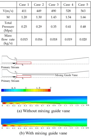
Case 1 Case 2 Case 3 Case 4 Case 5
V(m/s) 411 449 490 528 563
M 1.20 1.30 1.43 1.54 1.66
Total Pressure
(Mpa)
0.25 0.29 0.35 0.41 0.48
Mass flow rate
(kg/s)
0.015 0.016 0.018 0.019 0.020
Table 2. Computational Conditions at the Supersonic Nozzle Exit
Fig. 4 Contours of Mach Number and Sonic Line Location for Case 5
Fig. 5 Contours of Static Pressure (Case 5)
primary stream and secondary stream in the ejector-diffuser system were treated as ideal gas. Two-dimensional axial symmetric model, density-based solver, with the standard k-ω turbulent model was used in the computation.
Governing equations were discretized spatially with a finite volume scheme. Second-order MUSCL was used in turbulent kinetic energy as well as spatial discretizations.
Total pressure boundary conditions were used at the primary stream inlet. The boundary conditions of primary stream were specified at the exit of supersonic nozzle. The flow models were simulated for 5 different initial total pressures at the primary stream nozzle exit from 0.25 MPa to 0.48 MPa, as summarized in Table 2. Thus 5 different Mach numbers (M) ranging from 1.20 to 1.66 were used as reference values in the following investigation. The initial values can be calculated by these equations:
(1)
(2)
(3)where,
P : static pressure, Pa P0 : total pressure, Pa γ : ratio of specific heats M : Mach number at nozzle exit V : velocity, m/s
R : gas constant, J/kg·K T : temperature, K A : area, m2
ṁ : mass flow rate, kg/s
Ejector outlet was extended to stabilize the pressure outlet boundary conditions, so that
more accurate results can be obtained. The secondary stream inlet and the outlet of ejector-diffuser system were taken from ambient conditions at atmospheric pressure.
3. Results and Discussion
From the comparison of the results of the numerical analysis, higher pressure recovery increment and entrainment ratio increment can be found in case 5 with a Mach number of 1.66 as shown from Fig. 8 to Fig. 11. The following discussions are based on the CFD results of case 5.
In the geometry of ejector system, a very small diameter supersonic nozzle and a high length-diameter ratio of ejector system can be observed. This kind of ejector system model is beneficial to mixing two streams in the mixing chamber. Due to the high length-diameter ratio of ejector system, primary stream and secondary stream is mixed up before flowing into the diffuser. Thus, the mixed flow will be subsonic in the mixing chamber and lose momentum in the diffuser continuously. As a
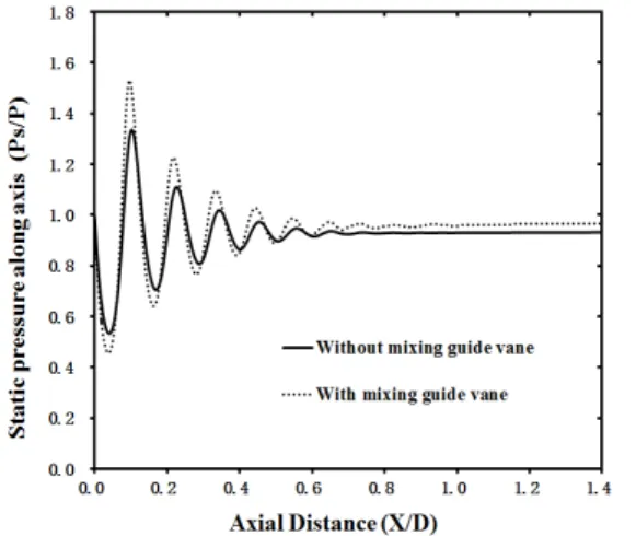
Fig. 6 Distribution of Static Pressures along Ejector Axis (Case 5)
result, discussion based on the contours in mixing process will be more meaningful.
Figure 4 shows the contours of Mach number around the primary stream inlet and sonic line location for case 5. Figure 5 shows the contours of static pressure around the inlet of ejector-diffuser system. The results are depicted for both models. For each figure, the upper field represents results for the model without mixing guide vane, while the results for the model with mixing guide vane are shown in the lower field. The different Mach number fields illustrate the different flow forms provided by both models in the Fig. 4.
The solid line in each field represents the sonic line where Mach number equals 1.
The high pressure primary stream, mainly discharged from the supersonic nozzle, entrains the low pressure secondary stream through pure shear action between the two streams. A series of shock waves could be found during the stream discharging and mixing processes. For both models, the first shock cell revealed a strong shock and continuous shocks occurred in the following mixing process. Indeed, more shock cells could
Fig. 7 Comparison of Momentum Ratio between With and Without Mixing Guide Vane
be found in the model with mixing guide vane, and a longer sonic line was showed in this case. Therefore, the mixing guide vane had a positive influence on the shock system itself and presented a certain appearance in the contours of Mach number in Fig. 4 and distribution of static pressures in Fig. 6.
However, it would be easy to think that a longer sub-critical area has a better promotion in the entrainment ratio[13].
Figure 5 shows the flow structures from other point of view of static pressure. The difference of the static pressure distribution between two models is illustrated in Fig. 6 while Ps is described as the static pressure along the ejector axis. As a result of energy exchange between both streams, the model with mixing guide vane achieves a higher static pressure than another model after shock wave, which would induce a higher pressure recovery of the ejector-diffuser system. The momentum ratio of secondary stream and primary stream was compared in Fig. 7. The influence on the secondary stream can be easily reflected on the momentum. The momentum ratio between two streams become
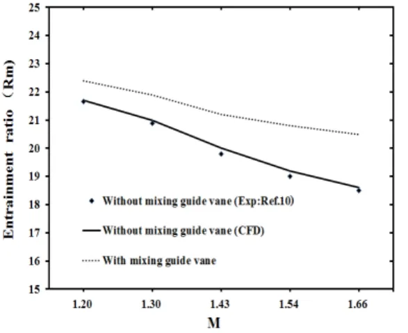
Fig. 8 Entrainment Ratio vs Mach Number at Nozzle Exit
larger as a result of installing the mixing guide vane. Less momentum loss and more energy saving were proved. This also shows that the optimized model gets a higher entrainment ratio and pressure recovery after final promotion in the diffuser.
3.1 Entrainment Ratio
Many kinds of flow characteristics can affect the performance of the ejector-diffuser system directly or indirectly. Entrainment ratio (Rm) is one of the most important parameters to describe the system performance, which can be influenced by geometry, back pressure as well as other operating conditions. The entrainment ratio (Rm) can be represented by the following equation:
(4)
In the present study, the entrainment ratio for different Mach numbers of primary stream is shown in Fig. 8 where the M ranges from 1.20 to 1.66. Results obtained from the computational analysis were similar with experiment results with a percentage deviation
Fig. 9 Comparison of Entrainment Ratio between With and Without Mixing Guide Vane
less than 3%. It is found that the entrainment ratio tends to decrease when the Mach number is increasing. The ejector-diffuser system with mixing guide vane shows better result of entrainment ratio in CFD analysis than the model without mixing guide vane.
The comparison of entrainment ratio between with and without mixing guide vane is illustrated in Fig. 9. Rm represents the entrainment ratio without mixing guide vane while Rm` represents the entrainment ratio with mixing guide vane. Indeed, the percentage increase of average entrainment ratio was about 6.8%, and the maximum amplitude of increase achieved was 13.1% in case 5. The increase amplitude in entrainment ratio became larger when the primary stream Mach number increased.
From the comparison between two models under different operating Mach numbers, the area of the mixing section and the productive capacity of primary stream were changed.
With a mixing guide vane, the flow vortexes were generated and more vertical flow was introduced into the stream. Therefore, rotary stream passed through the mixing chamber and introduced more shear stress to propel the secondary stream into the ejector-diffuser
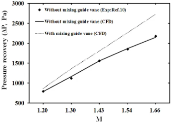
Fig. 10 Pressure Recovery vs Mach Number at Nozzle Exit
system, which effectively enhanced the performance of the ejector-diffuser system.
3.2 Pressure Recovery
Pressure recovery (ΔP) can be defined as the difference between static pressure at the secondary stream inlet (Ps) and static pressure at the outlet of ejector-diffuser system (Pt). The pressure recovery indicates the operational capability of ejector-diffuser system. The pressure recovery (ΔP) can be represented by the following equation:
∆
(5)The pressure recovery of the ejector-diffuser system for different cases was shown in Fig.
10. Results obtained from the CFD works were similar with experimental results and the percentage deviation was less than 5%. With the inlet stream Mach number increasing, the pressure recovery gradually becomes larger in both models. The ejector-diffuser system with mixing guide vane shows better pressure recovery than another model. The comparison of pressure recovery between with and without mixing guide vane is illustrated in Fig. 11. ΔP is described as the pressure
Fig. 11 Comparison of Pressure Recovery between With and Without Mixing Guide Vane
recovery without mixing guide vane and ΔP`
is described as the pressure recovery with mixing guide vane. The increase in amplitude of pressure recovery became larger when the primary stream Mach number increased. The ejector-diffuser system with mixing guide vane showed better pressure recovery. The difference of pressure recovery between two models was about 20.1%, and the maximum value of increase achieved was 26.6% when M=1.66.
The geometry of the diffuser in two cases was same while the mixing section was different. With a mixing guide vane, the flow vortexes were generated and more vertical flow was introduced into the stream.
Therefore, the mixing and energy transfer between the primary and secondary stream were increased, which effectively enhanced the pressure recovery of the ejector-diffuser system. Hence, addition of a mixing guide vane helps to mix the primary and secondary streams in the constant-area mixing section.
3.3 Total Pressure Loss Ratio
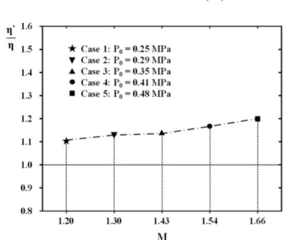
Total pressure loss ratio () can be considered as the difference between total pressure at the nozzle exit (P0) and total
Fig. 12 Comparison of Total Pressure Loss between With and Without Mixing Guide Vane
pressure at the outlet of ejector-diffuser system (Pt0). The total pressure loss ratio () can be represented as the following equation:
× (6)
Figure 12 shows the total pressure loss ratio of the ejector-diffuser system for different Mach numbers of primary stream. As the Mach number of primary stream increased from 1.20 to 1.66, the increase amplitude in total pressure loss became larger. The ejector-diffuser system without mixing guide vane shows better results in the total pressure loss ratio for all 5 cases. The increment of η between two models is about 14.8%, and the maximum value of increase achieves 19.8%
where the M=1.66. Although the addition of a mixing guide vane helps to mix the primary and secondary streams in the constant-area mixing section, the frictional force of mixing stream increased. At the same time, more flow losses were generated when the mixing guide vane was equipped in the secondary stream inlet. Indeed, the mixing guide vane enhanced the pressure recovery and also the total pressure loss of the ejector-diffuser system. But the enhancement of ΔP and η was still small for the low primary stream Mach number at the stream nozzle exit.
4. Conclusions
In the present paper, computational studies were carried out to investigate the supersonic ejector-diffuser system with a mixing guide vane at the inlet of secondary stream. The CFD simulation was carried out under different primary stream pressures and Mach
numbers. Results obtained from the computational analysis were similar with experiment results with a percentage deviation less than 3%. Therefore, the present results obtained were validated with existing experimental data.
The numerical simulation results with and without mixing guide vane have been compared. The mixing guide vane effects have been discussed in view of the performance improvement of the ejector system. The mixing guide vane improved the entrainment ratios, while causing the average entrainment ratio to increase 6.8%. The maximum increase amplitude in entrainment ratio was 13.1%. At the same time, the mixing guide vane leaded to a better pressure recovery of 19.8% in average and the largest increase amplitude of pressure recovery was 26.6%. On the other hand, total pressure loss ratio was increased in an average percentage of 15%. Further work is going on to optimize the mixing guide vane.
References
1. Riffat, S. B., Gan, G. and Smith, S.,
"Computational Fluid Dynamics Applied to Ejector Heat Pumps," Applied Thermal Engineering, Vol. 16, No. 4, 1996, pp.291-297 2. Riffat, S. B., Everitt, P., "Experimental and
CFD Modelling of an Ejector System for Vehicle Air Conditioning," Journal of the Institute of Energy, Vol. 72, 1999, pp.41-47 3. Huang, B. J., Petrenko, V. A., Chang, J. M.,
Lin, C. P. and Hu, S. S., "A Combined Cycle Refrigeration System Using Ejector-cooling as the Bottom Cycle," International Journal of Refrigeration, Vol. 24, No. 5, 2001, pp.391-399 4. Kumar, R. S., Kumaraswamy, S., Mani, A.,
"Experimental Investigations on a Two-phase
Jet Pump Used in Desalination Systems,"
Desalination, Vol. 204, No. 1-3, 2007, pp.437-447 5. Zhang, J. Z., Shan, Y., Li, L. G.,
"Computation and Validation of Parameter Effects on Lobed Mixer-ejector Performances,"
Chinese Journal of Aeronautics, Vol. 3, 2005, pp.93-198
6. Hong, W. J., Alhussan, K., Zhang, H., Garris, C. A., "A Novel Thermally Driven Rotor-vane/Pressure-exchange Ejector Refrigeration System with Environmental Benefits and Energy Efficiency," Energy, Vol. 29, No. 12-15, 2004, pp.2331-2345 7. Munday, J. T., Bagster, D. F., "A New
Ejector Theory Applied to Steam Jet Refrigeration," Ind. Eng. Chem. Proc. DD, Vol. 16, No. 4, 1997, pp.442-449
8. Riffat, S. B. and Omer, S. A., "CFD Modelling and Experimental Investigation of an Ejector Refrigeration System Using Methanol as the Working Fluid,"
International Journal of Energy Research, Vol. 25, No. 2, 2001, pp.115-128
9. Reinke, B., Neal, M. and Gupta, S. M.,
"Flow inside a Jet-ejector Pump for Vacuum Applications," Journal Ind. Inst.
Chem. Engrs., Vol. 3, 2002, p.44
10. Manohar, D.V., "Desalination of Seawater Using a High-efficiency Jet Ejector," Master Thesis, Texas A&M University, 2005
11. Holtzapple, M. T., "High-efficiency Jet Ejector," Texas A&M University, 2001 12. Somsak, W., "CFD Optimization Study of
High-efficiency Jet Ejector," Doctoral Dissertation, Texas A&M University, 2008 13. Amel, H., François, H., Sébastien, L.,
Jean-Marie, S., Yann, B., "CFD Analysis of a Supersonic Air Ejector. Part II: Relation between Global Operation and Local Flow Features," Applied Thermal Engineering, Vol. 29, No.14-15, 2009, pp.2990-2998