† Department of Civil Engineering, Daegu University (Corresponding Author : [email protected])
Effect of the Earth Pressure Coefficient on the Support System in Jointed Rock Mass
Moorak Son
†・ Solomon Adedokun
1)・ Youngcheol Hwang
2)Received: October 31
st, 2014; Revised: December 2
nd, 2014; Accepted: January 9
th, 2015
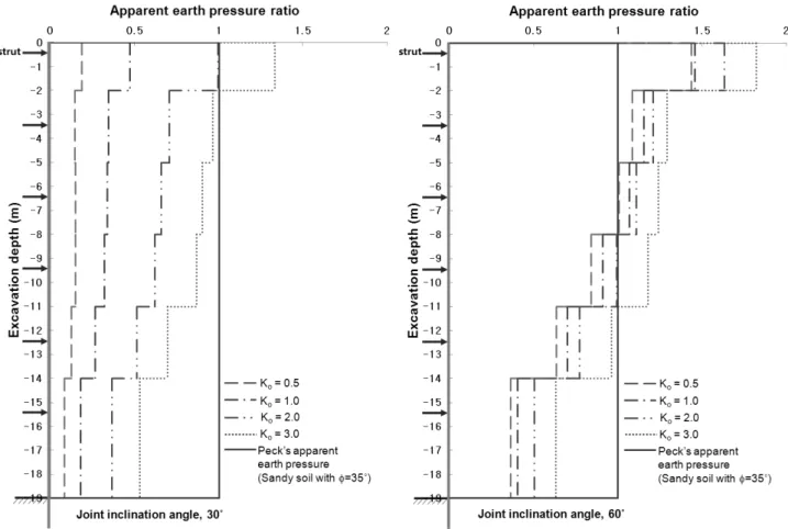
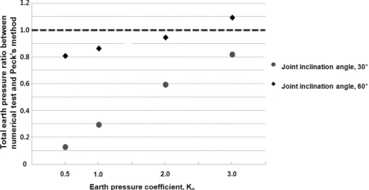
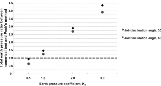
ABSTRACT : This paper investigated the magnitude and distribution of earth pressure on the support system in jointed rock mass by considering different earth pressure coefficients, rock types and joint inclination angles. The study mainly focused on the effect of the earth pressure coefficients on the earth pressure. Based on a physical model test (Son & Park, 2014), extended studies were conducted considering rock-structure interactions based on the discrete element method, which can consider the joints characteristics of rock mass. The results showed that the earth pressure was highly influenced by the earth pressure coefficients as well as the rock type and joint inclination angles. The effects of the earth pressure coefficients increased when the rock suffered more weathering and has no joint slide. The test results were also compared with Peck’s earth pressure for soil ground, and clearly showed that the earth pressure in jointed rock mass can be greatly different from that in soil ground. This study indicated the earth pressure coefficients considering the rock types and joint inclination angles are important parameters influencing the magnitude and distribution of earth pressure, which should be considered when designing the support systems in jointed rock mass.
Keywords : Rock excavation, Support system, Earth pressure, Earth pressure coefficient, Rock type, Joint inclination angle, Rock-structure interaction
Journal of the Korean Geo-Environmental Society 16(2): 33~43. (February, 2015) http://www.kges.or.kr
ISSN 1598-0820 DOI http://dx.doi.org/10.14481/jkges.2015.16.2.33
1. Introduction
Braced and underground excavations are extensively being utilized in congested urban areas for the construction of high- rise structures and underground facilities. However, the impact of these excavation works on the surrounding environment has become a major concern. Particularly, the miscalculation of earth pressure on excavation walls may cause the collapse of support systems in open cuts and eventually lead to the substantial time loss, financial damage, work stoppages, legal action, and compensation. Therefore, it is highly important to ensure the safety of support systems installed in underground structures and to minimize related problems (both social and economic ones). It is also necessary to clearly understand the behavioral characteristics of the ground and excavation walls and to have a clear understanding of ground-wall interactions.
The magnitude and distribution of earth pressure on the support walls caused by ground excavation works have been examined by several researchers through field measurements and physical model tests (Peck, 1969; Tschebotarioff, 1973;
Laio & Neff, 1990; Thompson & Miller, 1990; Lings et al.,
1991; Tanaka, 1994; Wong et al., 1997; Hashash & Whittle, 2002). Among them, Fig. 1 shows apparent earth pressure envelopes suggested by Peck (1969) and Tschebotarioff (1973), which are frequently used in practice for designing excavation support systems in soil ground. Numerical analyses have also been effectively utilized in many ways to predict the behavior of the of the excavation wall and the surrounding soil (Clough
& Hansen, 1981; Potts & Fourie, 1986; Clough et al., 1989;
Finno et al., 1991; Richards & Powrie, 1994; Goh et al., 1995; Hashash & Whittle, 1996; Ou et al., 1996; Lee et al., 1998; Hashash et al., 2003; Lawler et al., 2011; Worden &
Achmus, 2013). However, these existing studies were mainly
carried out on sandy and clayey soils but ground is made
up of not only soils but also rocks. There are also some
studies which measured the earth pressure on the retention
walls in multi-layered ground, including rocks (Chae & Moon,
1994; Jeong & Kim, 1997; Yoo & Kim, 2000). But these
studies only compare the earth pressure measured in multi-
layered soils with Peck’s earth pressure and the effects of the
earth pressure coefficients and joint conditions (joint inclination
angle and joint shear strength) were not considered. It is
Sand Soft to medium clay Stiff fissured clay (a) Apparent earth pressure (Peck, 1969)
Sand Temporary support in stiff clay Permanent support in medium clay (b) Apparent earth pressure (Tschebotarioff, 1973)
Fig. 1. Apparent earth pressure for soils very hard to find studies that have investigated the earth
pressure on support systems in rock strata containing systematic joints.
Few studies have examined the earth pressure in rock strata by considering ground-wall interactions and joint characteristics, which are important factors influencing the magnitude and distribution of the earth pressure. This might be due to the general misunderstanding that rock strata represent a better condition than soil ground. Recently, Son (2013), and Son
& Park (2014) presented the results of the earth pressures in jointed rock mass. Their results clearly showed that the earth pressure can be higher for rock strata than soil ground when the rock and joint characteristics are under unfavorable conditions, such as a joint condition that induces sliding and a weathered joint and rock condition. On the other hand, the earth pressure might be much lower than the soil ground when the rock conditions are favorable.
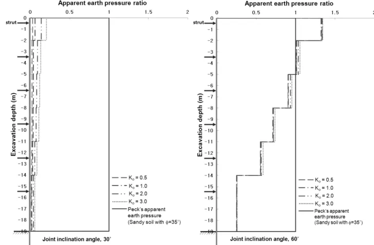
This study extended the previous studies, focusing on the effects of earth pressure coefficients for different rock types and joint inclination angles. Extended numerical parametric
studies were conducted by varying the earth pressure coefficient together with the rock types and joint inclination angles. The advantage of numerical analysis is not only various conditions can be considered easily with limited time, cost, and space, but also reproducible analyses are possible. This characteristic allows the effects of the earth pressure coefficients on the earth pressure to be investigated in various rock and joint conditions. The results from this study are expected to provide a better understanding of the earth pressure on the support system in a jointed rock mass that can experience different earth pressure coefficients.
2. Numerical approach and extended parametric study
The applied numerical approach in this study is similar to
the previous studies (Son, 2013; Son & Park, 2014), and the
following gives a brief description. The approach was verified
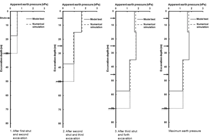
by the numerical simulation of a physical model test (Figs. 2
Fig. 2. Test preparation for physical model (Son & Park, 2014)
Fig. 3. Comparison between physical model test and numerical simulation (Son & Park, 2014) and 3) and the details of the verification are reported elsewhere
(Son & Park, 2014). The numerical approach was extended to this parametric study, which considered the effects of different earth pressure coefficients as well as rock types and joint inclination angles on the magnitude and distribution of earth pressure against the support in jointed rock masses.
To assess the characteristics of rock masses governed by joints, this study adopted 2-D Universal Distinct Element
Code (UDEC, 2004), which allows for large displacements between blocks. The rock blocks, wall and struts were simulated as separate elastic elements. The joints between the rock blocks and the interfaces between walls and rocks were modeled using the Coulomb slip model in which when the contact shear stress exceeds the contact shear strength the contact loses strength and sliding occurred.
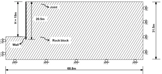
The analysis model was 68.8 m × 31.5 m and the excavation
Fig. 4. Numerical modeling (a case of joint inclination angle of 60°)
Table 1. Controlled parameters for numerical analyses Joint
Rock type Joint inclination angle (°) Joint shear condition Earth pressure coefficient
Hard 30, 60 Good 0.5, 1, 2, 3
Slightly weathered 30, 60 Fair 0.5, 1, 2, 3
Moderately weathered 30, 60 Poor 0.5, 1, 2, 3
wall was installed at the depth of 20.5 m (Fig. 4). The excavation width was assumed to be 20 m and the final excavation depth was 19 m. A strut-supported system was used because the apparent earth pressure (Peck, 1969), which was compared with this paper’s results, was obtained from many sets of comprehensive measurements of the strut load in strut-supported excavation walls for soil ground.
The study considered the different earth pressure coefficients and various arrangements of rock type and joint condition (Table 1). The joint inclination angle was measured in the anticlockwise direction from the horizontal plane, and the joint spacing was assumed to be 1 m to minimize the analysis time but to consider the effect of joints in the condition of the strut spacing of 3 m. For each of the cases, the analysis was carried out using soldier pile and timber lagging wall.
In order to reflect the general excavation procedures in the field, eight excavation stages were conducted to obtain the distribution and magnitude of earth pressure. Before the first excavation was carried out, the initial equilibrium was obtained with the at-rest earth pressure coefficient. At this stage, the boundary condition was a roller at each end of the two vertical boundaries and at the bottom boundary. After ensuring the initial equilibrium condition, all displacements were reset to zero and the wall was installed at a depth of 20.5 m. The
first excavation was conducted up to 1.0 m, followed by the installation of the first strut at 0.5 m over the excavation line. After the first excavation, there was additional excavation work every 3 m, which was followed by the strut installation at every 3 m interval (which is 0.5 m above each excavation line). Wall stabilization was ensured after each excavation stage. The final excavation was conducted up to 19.0 m, and no strut was installed in the final stage (see Fig. 5). Other analyses were also carried out for different earth pressure coefficients using the same procedures discussed above, whereas the earth pressure coefficients of 1.0, 2.0 and 3.0 were used to attain the initial equilibrium.
The shape of typical excavation wall (i.e. soldier pile and timber lagging wall) might have little effect on the earth pressure and wall displacement in the field as long as the flexural stiffness of the wall is equivalent. However, in a numerical analysis the shape may have a considerable influence on the results because of a stress concentration in modeling.
To address this issue, this study transformed the excavation
wall into a simple section to represent the equivalent flexural
stiffness of the wall (see Fig. 6). Table 2 shows the properties
of the wall, rocks, joints, and interfaces used in numerical
analysis. The assessment of the properties was discussed in
detail by Son & Yoon (2011).
Fig. 5. Excavation stages in numerical modeling (a case of joint inclination angle of 60°)
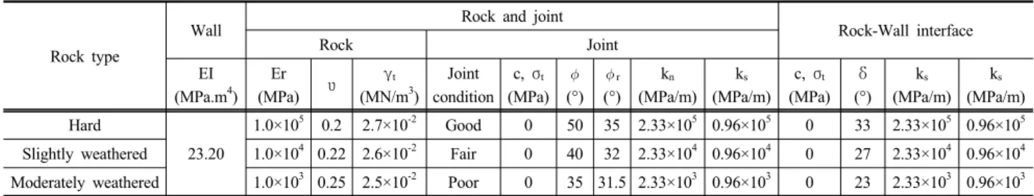
Table 2. Properties of wall, rock, joints and interfaces used in the numerical analysis
Rock type
Wall Rock and joint
Rock-Wall interface
Rock Joint
EI (MPa.m
4)
Er
(MPa) υ γ
t(MN/m
3) Joint condition
c, σ
t(MPa)
(°)
r