Performance of UAV(Unmanned Aerial Vehicle) Communication System Using Civil Wireless Mobile Networks
Byung-Seub Lee, Lifelong Member
ABSTRACT
Recently, demands on civilian UAV (Unmanned Aerial Vehicle) has been increasing and appropriate communication system is required for the UAV. In this paper, the performance of the UAV communication system using commercial wireless mobile network is discussed. The main service area of the wireless mobile network is ground level however the flying range of the UAV is normally in high altitude. Because of this mismatch of service area the performance of the UAV communication system is degraded in high altitude. To compensate performance degradation of the UAV communications system in high altitude, adaptive array antenna is introduced which is able to overcome altitude limitation of the UAV communication system.
Key Words : UAV, Commercial wireless mobile network,Wi-Fi Adaptive Array antenna.
*한국항공대학교 항공전자정보공학부([email protected])
접수일자 : 2017년 01월 15일, 수정완료일자 : 2017년 02월 01일, 최종게재확정일자 : 2017년 02월 02일
I. Introduction
Recently, demands on civilian wireless mobile networks for the UAV (Unmanned Aerial Vehicle) are increasing, along the increasing application of the UAV such as traffic monitoring and sports broadcasting, etc. Among the various wireless mobile networks, Wi-Fi, which is based on the OFDM (Orthogonal Frequency Division Multiplexing) system and widely used for wireless LAN, can be considered appropriate mobile communication system for the UAV since it can be easily accessible in relatively wide area. [1]
UAV team in the Korea Aerospace University has developed the UAV communication system based on commercial Wi-Fi system. Basically the service coverage area of the existing Wi-Fi gate station is ground level where most communication services are demanded by the subscribers who reside there. On the other hand the actual communications for the UAV are occurred in high altitude where gateway station of Wi-Fi normally neglects on purpose by tilting the antenna downward to focus ground level that is the actual service area. Therefore the performance of the UAV communication system using commercial wireless mobile networks cannot be guaranteed in high altitude. So without any measures, the UAV communication system based on civil communication mobile networks cannot do its mission successfully
particularly the mission with real time requirement. This property may restrict the possible civil and military service seriously. To solve this problem, some technical measures are taken either on gate station or on the UAV itself. Considering the slim demand of the UAV for the commercial mobile networks at the moment, the modification on the gate station is less feasible than the technical measures taken on the UAV.
In this paper, as one of the techniques applicable on the UAV side, the adaptive antenna array is considered and discussed. By adopting antenna array on bottom side of the UAV, the communication performance of the UAV is guaranteed even in high altitude without any modification on mobile gate station
Ⅱ. The Specification and Architecture of the UAV System
1. System Architecture and Dimension
Figure 1 illustrates the shape of the UAV that has been
used in the experiment. The UAV is equipped with
Two-Tail Boom of Pusher-type and the Wi-Fi
communication systems are loaded inside of body. Detail
Dimension and specifications of the UAV are shown in
Table 1.
Fig. 1. The shape and outlooks of the UAV
Table 1. Dimensions and Specifications of the UAV
Length (m) 2.3
Width (m) 2.5
Height (m) 1.11
Weight (kg) 15.00
Engine (cc) 48 (gasoline)
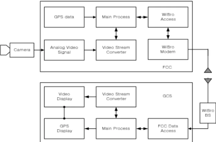
In Fig.2 the functional block diagram of the whole system both in the UAV and ground control site, is shown. As seen in Fig.2, the system is divided into two:
one is the payload system of the UAV and the other is Ground Control System.(GCC)
Fig. 2. The Fuctional block diagram of the system
The payload of the UAV consists of camera, Global Positioning System(GPS) and communication part that is called Flight Control Center.(FCC) While as the counterpart of the FCC, the Ground Control Center(GCC) is equipped with also back-to-back communication system and several human interfacing apparatus, such as monitors and keyboard, which are driven by main processor.
The signal between the FCC and the GCC can be summarized as follows. First of all, analog video signals acquired from camera are converted to digital video
stream data in the FCC and then it is encoded and compressed based on MPEC-4 protocol. The packetized video stream data are transmitted to GCS with GPS data over the Wi-Fi network. As a system to control the UAV on the ground, the GCS (Ground Control Center) send various environmental parameters and control information, and it receives video stream data as well as GPS data from the UAV. From the data received, the GCS main processor extracts the video and GPS information separately and then displays the information on the monitors. The data traffics flows between the FCC and the GCC are very much like the traffic flows between the personal user computer and server computer. The downlink data traffic, that is from the FCC to the GCC, are very much heavier than the opposite uplink data.
Because of this property, the asymmetrical channel allocation is desirable for the UAV application. The ideal maximum and average data rates of the domestic Fi-Wi networks provided by wireless mobile company are summarized in table 2.
Table 2. up-down link Data rate of Wi-Fi networks
MaximumData rate
Uplink 7.2Mbps
Downlink 18.4Mbps Average
Data rate
Uplink 1.2Mbps
Downlink 3-5Mbps
To check the actual average data rates achieved by the UAV modem using the gate station which is located in suburban area, transmission test is performed between the UAV modem and the GCC modem via local Wi-Fi gate station. As a results the actual data rates achieved are summarized in table 3.
Table 3. The real up-down link Data rate achieved
MaximumData rate
Uplink 346 Kbps Downlink 650 Kbps Average
Data rate
Uplink 200 Kbps Downlink 500 Kbps
The exact reason for this large discrepancy between the
proposed data rates by the wireless mobile company and
the actual data rate achieved by test is difficult to address
because there are many factors which affects the data
transmission performance between the UAV modem and
the GCC modem such as shadowing, multipath fading
effects of the channel besides the performance of the wi-fi modem itself. Anyway to provide the UAV service without glitch, the data transmission rate between the UAV and the GCC shoud be considered. This actual transmission data rates are measured on the ground level using the wi-fi modem installed in a car moving around the gate station. However the actual data transmission rate in high altitude where the UAV is cruising is expected even lower.
Ⅲ. Adaptive Antenna Array for High Altitude Communication
To ensure high altitude communication of the UAV using commercial wireless mobile networks, system enhancement either on the gateway station or the UAV in terms of antenna gain can be considered. Before the advent of specially designed gateway station maintaining antenna beam coverage at high altitude for the UAV it is very hard to guarantee the quality of communication of the UAV which has to rely on the civil mobile network only. Further it is expected even more difficult to modify the existing gateway station to cover both region :high altitude and ground.
So more practical approach is modifying the UAV to maintain received RF signal level above the threshold. As can be seen in Fig.3, by installing adaptive antenna array on the bottom section of the UAV which will automatically tracking gateway station, the UAV can maintain the RF signal level high enough to secure reliable communication between the UAV and gateway station.
Fig. 3. The concept of the UAV adaptive antenna array
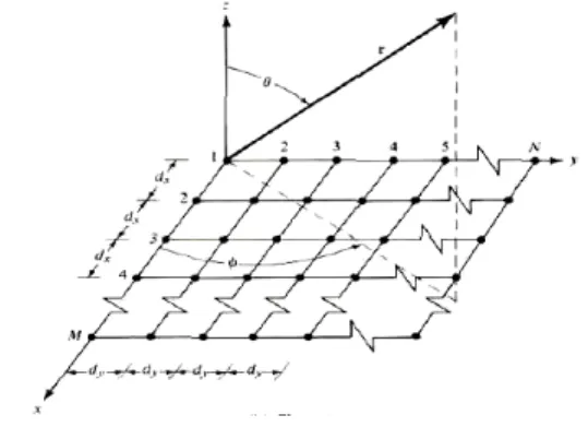
The proposed adaptive antenna is M-by-N planar array which forms narrow beam to the gateway station in order to enhance RF signal level. Figure 4 illustrates M-by-N
two-dimensional planar array antenna structure[2], [3].
Fig. 4. M-by-N two dimensional planar array
As shown in Fig. 4, there are M-elements in the x-direction and N-elements in the y-direction creating an M-by-N array of elements. The m-nth element has weight of . The x directional elements and y directional elements are spaced , respectively. The pattern of the entire M-by-N elements array using pattern multiplication can be expressed as equation (1),
( 1)( )
( 1)( )
1 1
( 1)( ) ( 1)( )
1 1
y y
x x
x x y y
x y
M N
j m j n
m n
m n
M N
j m n
mn m n
AF AF AF
a e b e
w e
d x d x
d x d x
- +
- +
= =
é - + + - + ù
ë û
= =
= ×
é ù é ù
= ê ú ê × ú
ë û ë û
=
å å
åå
0 0
0 0
sin cos sin sin
, sin cos
sin sin
x x
y y
x x
y y
kd where kd
kd kd
d q f
d q f
x q f
x q f
ì =
ï =
ï í = - ï ï = -
î (1)
Where , are current strength of m,n th array elements, multiplication of which are interpreted as magnitude of antenna weights, . and ,
are its phase delay. After normalization by maximum value eq. (1) becomes eq. (2).
sin( ) sin( )
2 2
( , )
sin( ) sin( )
2 2
x y
n
x y
M N AF
M N
y y
q f y y
æ ö
æ ö
ç ÷
ç ÷
ç ÷
= ç ÷ ×
ç ÷
ç ÷
ç ÷ ç ÷
è ø è ø
(2)
, x x x
y y y
where y d x
y d x
= +
ì ï
í = +
ï î
and , is angle of main beam. To avoid
grating lobe, the space between the array element should
be less than . And then main lobe angle can be gotten as eq. (3),(4).
sin
cos
sin cos ±
(3)
tan
sin cos ± sin sin ±
(4)
Assuming that the target gateway station is just below the UAV, the direction of main beam can be set as
, . However, as shown in Fig.5, angles of main beam are slanted by rolling and pitching movement of the UAV; resultantly, the actual directions of main beam are ′ ≠ , ′ ≠ . With this situation, even if the UAV is just flying over the gateway station, the main beam cannot be aligned to the direction of the gateway station because of attitude of the UAV. So regardless of the UAV attitude, if the direction of the main beam is to be kept as vertical to the ground, special adjustment system, shown in Fig.6, is required.
Fig. 6. Block diagram of the phase correction system
With the measurement devices, gyro censor and accelerometer, rolling and pitching angle of the UAV are calculated to make the direction of the main beam is vertical to the ground, whatever the attitude of the UAV may be. The concept of main beam correction is shown in Fig.6.
Fig. 7. Concept of correcting the direction of the main beam
Where are slant angles of airframe that is acquired from measurement devices. Measured angles of Cartesian coordinates, are converted into angles of spherical coordinates in the phase corrector. And antenna beam pattern is adaptively corrected by adjusting phase of main beam. Then antenna beam pattern is formed vertically for the ground. By the eq. (5),(6), the adjusted angles, ′ ′ are gotton from the measured parameters,.
1
1 cos tan 1 cos f b
a
-
-
¢ = - (5)
( )
cos
1cos cos 1
q ¢ =
-a + b - (6)
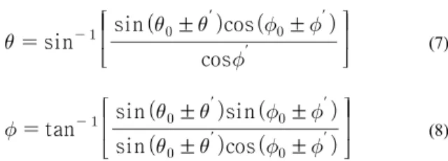
And the final correcting angle is gotten by the eq.(7),(8).
sin
cos ′
sin ± ′ cos ± ′
(7)
tan
sin ± ′ cos ± ′ sin ± ′ sin ± ′
(8)
Azimuth angle and elevation angle adjusted by Eq.
(7),(8) always point the sub-UAV point : the ground position that is vertically linked to the UAV. However the gateway station the UAV has to communicate is seldomly positioned vertical-wise; rather the LOS line between the UAV and gateway station is likely slant-wise according to the position parameter of the UAV and the gateway station mostly represented by global position system(GPS) data. To steer the main beam to the gateway station eq.(7),(8) readjusted according the elevation and azimuth angle of the gateway station from the UAV. Unlike ′ ′ which have to calculate from the sensor data, the elevation angle( ″ ) and azimuth angle( ″ ) from the UAV to the gateway station can be gotten from the GPS data of the UAV and gateway station. So the final elevation and azimuth angles are got as following Eq.(9),(10):
sin
cos ′ ± ″
sin ± ′ ± ″ cos ± ′ ± ″
(9)
tan
sin ± ′ ± ″ cos ± ′ ± ″ sin ± ′ ± ″ sin ± ′ ± ″
(10)
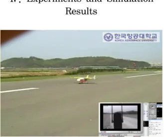
Ⅳ. Experiments and Simulation Results
Fig. 7. The UAV figure and Image by Onboard Camera
Fig.7 shows the takeoff image of the UAV and its image captured by onboard camera.
Fig.8 shows the moving picture of campus building relayed in real time on wi-fi network.
Fig. 8. Picture relayed in real time on wi-fi networks
During experimenting, the altitude and distance of the UAV from the wi-fi gateway station should be within limited range in order to make the communication link between the UAV and the gateway station secured.
Besides the pictures taken by camera, status of the UAV, such as GPS data, are also transferred to the GCC as shown in Fig.9
Using the commercial mobile networks the UAV can provide a lot of useful service such as traffic monitoring, sports broadcasting relay and so on.
Fig. 9. the UAV GPS data transffered
The aerial view of local marathon competition relayed in real time on commercial wireless networks is valuable because this kind of aerial view can not be procured by conventional broadcasting system. However there is big disadvantage using commercial wireless networks for the UAV communication.
Fig. 10. The local Marathon Competition shot by the UAV
Most wireless network services are likely targeting the residence on the ground level so the wireless mobile antenna on the gateway station are tilted downward to concentrate power on the ground level. Because of this fact, the UAV navigating around the gateway station in high altitude is very likely loss its communication link to the gateway station.
To alleviate this kind of symptom, the adaptive antenna array system is proposed. With the adaptive antenna system proposed, the UAV will keep tract of the gateway station wherever navigate around the gateway station.
The antenna radiation pattern of the adaptive antenna
array is shown in Fig. 11.
-45 -36 -27 -18 -9 0
60
120
30
150 0
180 30
150 60
120
90 90
Polar plot of Relative Directivity (0<f<360o)