1.
(rotor blade) (casing)
(stator vane)
, (tip clearance)
.
(pressure surface) (suction surface)
2 ,
(tip-leakage flow) .
Mayle
Metzger
(1).
(cascade) .
(2-5)Jin Goldstein
(6).
(turning angle) 107 ,
(span-to-chord ratio) 2.5
.
.
. 1
Measurement of Thermal Load in the Tip-Clearance Region of a Rotor Surface
Sang Woo Lee, Hyun Goo Kwon, and Jin Jae Park
Key Words: Tip-Leakage Flow ( ), Tip Clearance ( ), Heat (Mass) Transfer Coefficient ( ( ) )
Abstract
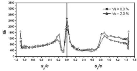
The heat (mass) transfer characteristics in the tip-leakage flow region of a high-turning first-stage turbine rotor blade has been investigated by employing the naphthalene sublimation technique. The heat transfer data in the tip-leakage flow area for the tip clearance-to-span ratio, h/s, of 2.0% are compared with those in endwall three-dimensional flow region without tip clearance (h/s = 0.0 %). The result shows that the thermal load in the tip-leakage flow region for h/s = 2.0% is more severe than that in the endwall flow region for h/s = 0.0%. The thermal loads even at the leading and trailing edges for h/s = 2.0% are found larger than those for h/s = 0.0%. The tip-leakage flow results in heat transfer augmentations near the tip on both pressure and suction sides in comparison with the mid-span results.
,
E-mail : [email protected]
TEL : (054)467-4209 FAX : (054)467-4050
* ,
** ,
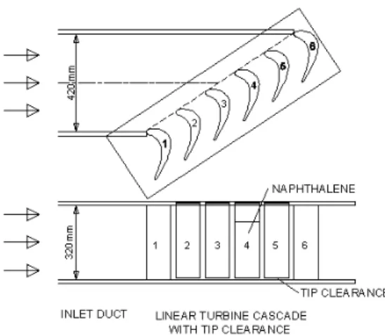
Fig. 1 Turbine rotor cascade with tip clearance
, ( )
.
2.
,
, .
9.0 ,
40 m/s .
(Fig. 1).
420 mm × 320 mm ,
1.2 m .
6
. 1
(mid-span)
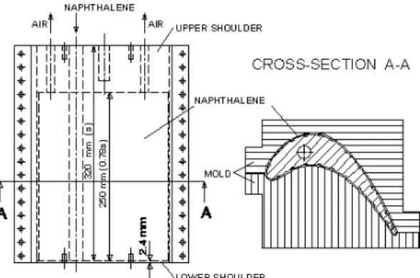
large-scale . Fig. 2
, (c),
(p), (s) 217.8 mm, 151.6 mm,
320.0mm .
119 Goldstein
(6)
107 12 .
(7)