62
http://dx.doi.org/10.21289/KSIC.2016.19.2.062 한국산업융합학회 논문집 제19권 제2호
24 GHz 안테나 모듈을 이용한 2차원 레이더 거리 측정 시스템 개발 및 성능 평가
Development of 2-Dimension Radar Distance Measurement System with 24 GHz Antenna Module and Its Performance
Evaluation
고석조1*, 김태훈2, 차병수3, 박민규4, 문영근5, 유기호5
Seok-Jo Go
1*, Tae-Hoon Kim
2, Byung-Soo Cha
3, Min-Kyu Park
4, Young-Gun Moon
5, Ki-Ho Yu
5<Abstract>
Laser distance measuring systems are used in many fields with high precision.
However, when measuring the reflector such as the mirror and the black color, a laser distance measuring system does not guarantee the measurement accuracy. In order to measure the shape of the cargo, this study proposes the radar distance measurement system. The radar distance measuring system is composed of a distance measuring unit with a 24 GHz antenna module, a signal processing and control board and the 1-axis tilting unit. And, this study developed a monitoring program to monitor the measured data. In order to evaluate performance of the developed system, the distance measurement tests are carried out. The distance error was about 6-15 cm.
However, considering the size of the cargo, the precision is not a problem. And, cargo shape was measured by using the distance information measured by the 1-axis tilting unit. It could get a 2 dimension shape profile for the cargo stacked in a yard.
Keywords :
Laser distance measuring system, Radar distance measurement system, 24 GHz Antenna module, Signal processing and control board, Tilting unit
1. 교신저자, 정회원, 동의과학대학교 기계계열 교수, 工博 E-mail : [email protected]
2. 동의과학대학교 전자과 3. 동의과학대학교 산업디자인과 4. 영남이공대학교 기계계열 5. 엔비코어
1. Corresponding Author, Division of Mechanical Engineering Dongeui Institute of Technology, Prof. Ph.D.
2. Electronic Engineering, Dongeui Institute of Technology 3. Industrial Design, Dongeui Institute of Technology 4. Division of Mechanical Eng., Yeungnam University College 5. NBCORE
1. 서 론
국내 제철소, 화력발전소 등에서는 수입된 원료 를 하역하기 위해 언로더(unloader)를 사용하고 있다1). 이러한 하역 작업 시에는 선박 구조물과 언로더 충돌, 원료에 의해 버킷이 묻히는 경우 등 이 발생할 수 있으므로 하역 상황에 대한 정보를 운전자에게 제공할 필요가 있다.
본 연구의 선행연구에서는 선박 화물 및 원료 등을 하역하는 과정에서 하역 상황에 대한 정보를 운전자에게 제공하기 위하여 선박의 해치부 및 화 물 형상 스캔을 위한 3차원 레이저 거리 측정 시 스템을 개발하였다2-4).
레이저를 이용한 측정 시스템은 측정에서의 높 은 정밀도로 다양한 분야에서 사용되고 있다. 그 러나 거울과 같은 반사체, 검은 색상 등의 측정에 서는 측정 정밀도를 보장하지 못하는 문제를 가지 고 있다. 한편 레이더 거리 측정 시스템은 레이저 거리 측정 시스템에 비교해서 정밀도는 낮으나 레 이저 시스템이 감지하지 못하는 반사체 및 검은 색상을 감지할 수 있으며 눈, 비, 먼지 등의 외부 환경 변화에도 강인한 특성을 가지고 있다5-6).
본 연구에서는 빔(beam)의 폭이 좁은 밀리미터 파장 영역대의 레이더를 사용한 레이더 거리 측정 시스템을 개발하고자 한다. 레이더 거리 측정 시 스템은 24 GHz의 안테나 모듈을 이용한 거리 측 정부와 2차원 측정 데이터 획득을 위한 1축의 틸 팅부로 구성되어 있다.
2. 레이더 거리 측정 시스템 개발
2.1 혼 형상 비교 테스트
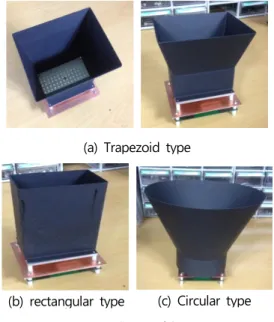
레이더 거리 측정 시스템 설계에 앞서 혼의 입
구 통로 형상에 따른 전파 수신 특성을 파악하기 위해 Fig. 1과 같이 사다리꼴형, 사각형, 원형 등 의 입구 형상을 고려하였다. 사다리꼴 혼 형상은 빔의 폭을 줄여주는 역할을 하도록 제작하였으며 노이즈 제거를 위해 동판을 설치하였다. 사각 기 둥 형상은 수신 주파수를 모으는 형상을 검토하기 위해 제작하였으며 빔의 폭을 7×5 degree 까지 줄이도록 하였다. 실험에 사용된 레이더는 Fig. 1 (a)와 같이 24 GHz 패치 안테나/트랜시버 모듈 (patch antenna/ transceiver module)을 사용하 였으며 그 사양은 Table 1과 같다7).
(a) Trapezoid type
(b) rectangular type (c) Circular type Fig. 1 Shape of horn.
Item Specifications
transceiver 24 GHz (K-Band) short range
antenna Dual 54 patch narrow beam
Elevation
beam Angle 25 degree Azimuth
beam Angle 7 degree
Table 1. Specifications of the patch antenna/
transceiver module.
64 한국산업융합학회 논문집 제19권 제2호
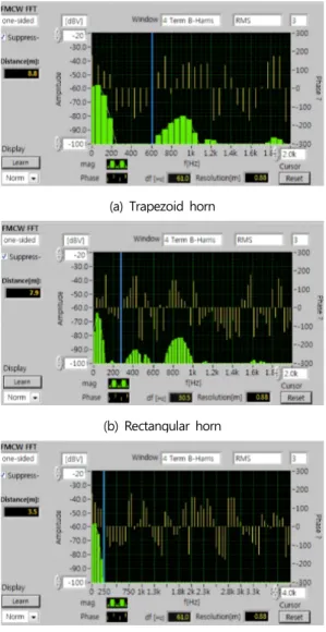
(a) Trapezoid horn
(b) Rectangular horn
(c) Circular horn
Fig. 2 results of experiment.
3가지 혼 형상에 대한 감지 평가를 위해 8 m 전방에 차량을 위치시키고 차량에 대한 레이더 감 지 측정 실험을 하였다. 측정 결과는 Fig. 2와 같 다. 가로축은 수신 주파수 거리를 나타내고, 세로 축은 측정 감도 세기를 나타낸다. 각 그래프에서 앞부분에 나타난 신호부분은 노이즈 신호로 필터 링을 통해 해결 가능하다. 실험 결과를 보면 사다 리꼴 형상의 혼이 가장 신호를 잘 수신한 것으로 나타났다. 주파수의 직진성을 고려해서 제작한 사
각 형상에서는 수신 결과 노이즈 신호가 많이 발 생하였다. 그리고 원형 혼에서는 수신 감도가 좋 지 않아 차량을 감지하지 못하였다.
2.2 레이더 거리 측정 시스템 제작
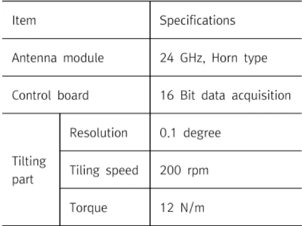
개발한 레이더 거리 측정 시스템은 Fig. 3과 같 고 안테나 모듈, 신호처리 및 제어 보드, 1축 틸 팅부 등으로 구성되어 있다. 레이더 거리 측정을 위해서는 RF Beam 사8)의 24 GHz 안테나 모듈 을 이용하였으며 신호처리 및 제어를 위한 회로부 를 Fig. 4와 같이 제작하였다. 그리고 레이더의 회전을 위해 1축 틸팅부를 제작하였다. 개발된 레 이더 거리 측정 시스템의 사양은 Table 2와 같다.
Fig. 3. Radar distance measurement system.
Fig. 4. Signal processing board.
Item Specifications Antenna module 24 GHz, Horn type Control board 16 Bit data acquisition
Tilting part
Resolution 0.1 degree Tiling speed 200 rpm
Torque 12 N/m
Table 2. Distance measuring unit.
2.3 모니터링 프로그램 개발
측정된 거리 정보들을 이용하여 물체의 위치를 확인하고 사용자가 인지할 수 있는 거리 정보로 나타내어 주기 위해서는 모니터링 프로그램이 필 요하다. Fig. 5는 본 연구에서 개발한 모니터링 프로그램을 나타낸다.
Fig. 5. Monitoring program.
Fig. 5에서 왼쪽 그래프는 측정된 물체의 위치 를 나타낸다. 가로와 세로 반경 방향의 값(0~255) 은 측정 시스템으로 부터의 거리를 나타내며 원주
상의 값은 측정 시스템의 정면 기준 방향과 측정 대상 물체 사이의 각도를 나타낸다. 가운데 표는 측정된 값을 미터 단위로 환산하여 나타낸 것이 다. 그리고 오른쪽 그래프는 측정된 거리 정보의 신호 크기를 나타낸다.
3. 성능 평가
3.1 거리 측정 평가
개발된 레이더 거리 측정 시스템에 대한 거리 측정 성능 평가를 하기 위해 Fig. 6과 같이 구성 하였다. 그리고 기준 거리 측정을 위해 보쉬 (Bosch) 사의 레이저 거리 측정기(DLE70)를 사용 하였다9).
Fig. 6. Distance measurement test of the developed radar distance measurement system.
타겟 보드를 이동하면서 보쉬 사의 레이저 거
리 측정기에 의한 거리 측정과 본 연구에서 개발
된 레이더 거리 측정 시스템에 의한 거리 측정 실
험을 Fig. 7과 같이 하였으며 측정된 결과를 표 3
과 같이 비교하였다. 본 연구에서 개발된 레이더
거리 측정 시스템에 의해 약 6~15 cm의 거리 측
66 한국산업융합학회 논문집 제19권 제2호
정 오차가 발생하였다. 본 연구에서 개발하고자 하는 레이더 거리 측정 시스템은 레이저 측정 시 스템으로 감지할 수 없는 화물의 형상 정보를 운 전자에게 제공하는 것을 목적으로 하기 때문에 화 물의 전체 크기를 고려할 때 정밀도 측면에서 문 제는 없다.
Fig. 7. Experiment for measuring a distance.
Laser distance measurement device(BOSCH)
Developed
system distance error
5.375 m 5.438 m 6-14 cm
9.207 m 9.300 m 9-15 cm
12.126 m 12.200 m 7-12 cm
Table 3. The measured distance.
3.2 형상 측정 평가
개발된 시스템의 화물 형상에 대한 측정 평가 를 위해 Fig. 8과 같이 야적장의 화물에 대한 형 상 프로파일을 측정하였다.
Fig. 9는 야적장의 화물에 대한 스캐닝 결과 그 래프를 나타낸다. 그래프의 원점에서 반경 방향은 측정 시스템으로 부터 측정된 화물의 반경 방향
거리를 나타내며 원주 상의 각도 값은 초기에 측 정기의 정면 방향을 90도로 두었을 때의 측정기 의 회전 각도값을 나타낸다.
1축 틸팅부에 의해 회전하면서 측정된 거리 정 보를 이용함으로써 화물이 쌓여 있는 2D 형상 프 로파일을 획득할 수 있다.
Fig. 8. Shape measurement test of the developed radar distance measurement system.
Fig. 9. Scanning Result.
4. 결 론
레이저를 이용한 형상 측정 시스템은 측정에서 의 높은 정밀도로 다양한 분야에서 사용되고 있으 나 거울과 같은 반사체, 검은 색상 등의 측정에서 는 측정 정밀도를 보장하지 못하는 문제가 있다.
본 연구에서는 24 GHz의 안테나 모듈을 이용한
거리 측정부와 2차원 측정 데이터 획득을 위한 1
축의 틸팅부로 구성된 레이더 거리 측정 시스템을 개발하였다. 개발된 레이더 거리 측정 시스템에 대한 거리 측정 성능 평가에서는 약 6~15 cm의 거리 측정 오차가 발생하였으나 화물의 전체 크기 를 고려할 때 정밀도 측면에서는 문제가 없다. 그 리고 화물 형상에 대한 측정 평가에서는 1축 틸 팅부에 의해 회전되면서 측정된 거리 정보를 이용 함으로써 야적장에 쌓여 있는 화물에 대한 2D 형 상 프로파일을 획득할 수 있었다.
후기
본 연구는 중소기업청에서 지원하는 2014년도 산학연협력 기술개발사업(기업부설연구소 신규설 치)(No. C0185261)의 연구수행으로 인한 결과물 임을 밝힙니다.
참고문헌
[1] H. S. Han, "A study on shape and flexural rigidity of bucket lip for continuous ship unloader," Master’s thesis, Gyeongsang National University, 2013
[2] S. J. Go, T. H. Kim, B. S. Cha, M. K.
Park, K. H. Yu and Y. G. Moon, "A study on Development of 3D Laser Scanning System Using 2D Laser Scanner," Proceeding on KSIA Autumn Conference, pp. 154-155, CECO, Changwon, Korea, 2014
[3] Y. G. Moon, S. J. Go, K. H. Yu and M.
C. Lee, "Development of 3D Laser Range Finder System for Object Recognition," Proceeding on IEEE/ASME International Conference on Advanced Intelligent Mechatronics, pp. 1402-1405, BEXCO, Busan, Korea, 2015
[4] S. J. Go, T. H. Kim, B. S. Cha, M. K.
Park, K. H. Yu and Y. G. Moon,
"Development of a 3D Laser Scanning System for Scanning a Shape of Hatch and Cargo Holder on a Cargo Ship,"
Journal Korean Society Mechanical Technology, Vol. 18, No. 2, pp.
288-293, 2016
[5] B. W. Kim, J. Hur, "Radiation
Characteristics of Parallel Slot Antenna for
Automotive Radar System," Trans. KIEE,
Vol. 59, No. 11, pp. 1980-1985, 2010
68 한국산업융합학회 논문집 제19권 제2호
[6] S. H. Park, I. S. Choi, S. J. Lee, S. J.
Lee and J. H. Jin, "A Study on the System Design for Intelligent Automotive Radar," The Journal of Korea Institute of Information Technology, Vol. 10, No.
2, pp. 62-69, 2012 [7] www.conti-online.com [8] www.rfbeam.com [9] www.bosch.com
(접수:2016.05.18. 수정:2016.05.26. 개제확정:2016.06.08.)