• 검색 결과가 없습니다.

Strength Properties of Wooden Retaining Walls Manufactured with Pinus rigida Miller

N/A
N/A
Protected

Academic year: 2021

Share "Strength Properties of Wooden Retaining Walls Manufactured with Pinus rigida Miller"

Copied!
8
0
0

로드 중.... (전체 텍스트 보기)

전체 글

(1)

*1 Received on November 3, 2010; accepted on January 5, 2011

*2 Hwacheon Clean Industry Promtion Foundation, 1146-5, Woncheon-ri, Hanam-myeon, Hwacheon-gun, Gangwon-do 209-842, Korea

*3 Department of Forest Biomaterials Engineering, College of Forest and Environmental Sciences, Kangwon National University, Chuncheon 200-701, Korea

*4 Div. of Environmental Wooden Material Engineering, Dept. of Green Resources Utilization, Korea Forest Research Institute, 57 Hoegi-ro, Dongdaemun-gu, Seoul 130-712, Korea

Corresponding author : Soon-Il Hong (e-mail: [email protected])

Strength Properties of Wooden Retaining Walls Manufactured with Pinus rigida Miller* 1

Jun-Chul Park*

2

, Keon-Ho Kim*

3

, Dong-Heub Lee*

4

, Dong-Won Son*

4

, and Soon-Il Hong*

3†

ABSTRACT

The strength properties of wooden retaining wall which was made with pitch pine were evaluated.

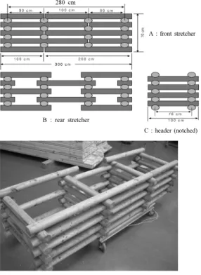
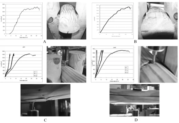
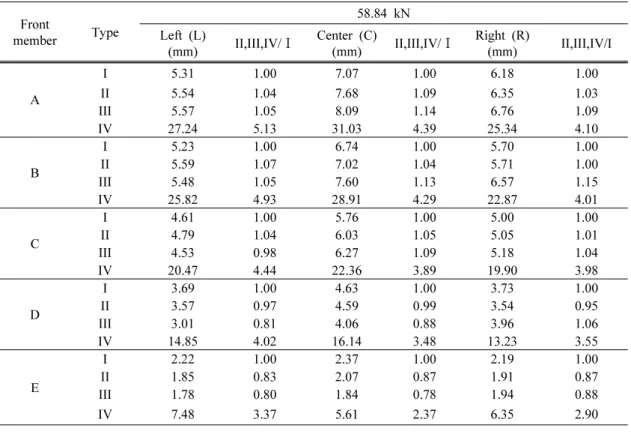
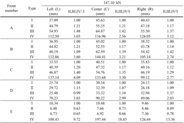
Wooden retaining wall was made with diameter 90 mm of pitch pine round posts treated with CUAZ-2 (Copper Azole). The length of the front stretcher of the retaining wall was 3,000 mm. The distance be- tween the headers (the notched member) is 1,000 mm in center and is 900 mm in side. There were con- nections every 2,000 mm because actually the length of stretcher is limited in the retaining wall. The strength test was carried out according to connection type because the section between stretchers can act as a defect. A result of the strength test according to connection type confirms that connection does not act as defect because the strength of retaining wall in single stretcher is similar to that in the section be- tween stretchers. The strength test of the wooden retaining wall was carried out in 5 types according to the condition of the base section. When the upper soil pressure was 9.8 kN/m

2

, the maximum load of the retaining wall fixing the front foundation shows higher values than those of others. But the total de- formation is lower in the retaining wall not to fix a base section than in that to fix a base section. It is thought that the retaining wall not to fix a base section shows low value because the deformation is distributed throughout the retaining wall and it is confirmed that the soil pressure affects supporting the structure because the deformation of the retaining wall under low pressure is 3∼4 fold higher than those of others. The failure mode of the retaining wall is the overturning type because the high section is deformed. Mostly, the failure mode is the separation of the header in the notched section.

Keywords : retaining wall, Pinus rigida Miller, image process

(2)

1. INTRODUCTION

In 1960s Pinus rigida Miller was afforested more than Larix leptolepis in Korea, because it can root well in a barren mountainous district and occupies 15.2 percent of accumulated quan- tity in forest trees and 13.4 percent of total for- est area. About 40 years after afforestation, al- most all afforested trees have reached a final age. Cutting tree is increased to plant more eco- nomical species of trees, because at present eco- nomical efficiency is considered more im- portantly than rapid growth and so Pinus rigida Miller is recognized as useless. It is urgently re- quired to find where Pinus rigida Miller can be used, because falling trees has been increased.

In Japan Forest Agency has educated the im- portance of utilization of domestic wood and has made an effort to use more domestic wood through national movement since 2005. To use the logged tree, recently, a soil Erosion Control Dam, a retaining wall and a debris barrier using wood have been developed in South Korea (Ryu and Jang, 1998; Ryu et al., 1999; Lee et al., 2007). If the slope on a foundation of the earth surface is steeper than a stable slope, the retaining wall as the structure to prevent the foundation collapsing is used to pile up soil, to clear forest and to fill up seashore (Paik and Lee, 1983; Bullen et al., 1992). The height of the gravity retaining wall is below 3 m. A member composing the structure, a fastener, an assembly of connection, and etc. are important in controlling wall strength (Bae et al., 2007).

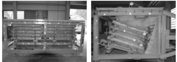
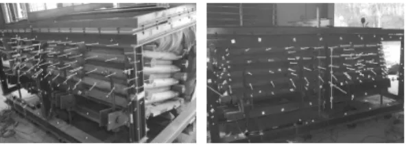
The aim of the present paper is to use Pinus rigida Miller in the retaining wall. This paper reports the results obtained by comparing the strength properties and the deformation by the horizontal load of each wooden retaining wall in the foundation. In the strength test, the re- taining wall was set in the strength test machine and tested, changing foundation fixing condition

and upper part pressure.. The 3D space de- formation was checked, using AICON 3D DPA- PRO system.

2. MATERIALS and METHODS

2.1. Materials

The round post (Pinus rigida Miller), of which the diameter is 90 mm and which was treated with CUAZ-2 (Copper Azole), was ob- tained from Joong-dong Co.. The moisture con- tent of the round post had cured for 15 days at room temperature was 16∼27%. The retaining wall was consisted of the 1,000 mm long head- er and the 2,000 mm long stretcher.

2.2. Manufacturing

2.2.1. Retaining Wall Manufacturing

Round posts of 1,000 mm and 2,000 mm used in the front side of the retaining wall were piled up, changing the position of post in order that the connection of wall is crossed. The total length of stretcher in the front side was 3,000 mm and the span between notched posts was 1,000 mm. The stretcher of the rear section was connected as shown in Fig. 1-B, and an empty space was made in the rear section to enter soil.

The stretcher in the rear section was piled up

with the 1,200 mm long round post, crossing

each floor. One hundred centimeter long notch-

ed post was used as the header, and the span

between the notches, which is the distance be-

tween the front and the rear stretcher, was 760

mm. When manufacturing the retaining wall,

the screw (H/W #14 × 120) was used as the

connector of the round post. The retaining wall

was consisted of 5 layers of the front and rear

stretcher and 4 layers of header. The size was

3,000 mm by 700 mm.

(3)

280 cm

A : front stretcher

C : header (notched) B : rear stretcher

Fig. 1. Retaining wall design.

A B

C D

Fig. 2. Connections of retaining wall.

Fig. 3. Strength test of the retaining wall loaded horizontally.

2.2.2. Manufacturing of Connection in the Retaining Wall

The connection specimens were made in the same type as the connection of retaining wall.

Four types of connections were made as shown in Fig. 2. The connection specimens were div- ided into two groups. Type A and B had a con- nection between stretcher and header, and Type C and Type D had two connections. Type A connected with a stretcher was consisted of two headers (500 mm) and a stretcher (200 mm), and was connected with a H/W #14 × 120 screw. Type B was consisted of two headers (500 mm) and two stretchers (100 mm) instead of the 200 mm long stretcher of Type A, and two stretchers were connected with two screws at 100 mm apart from the end of the header.

Type C was consisted of a stretcher (1,200 mm) and four headers (500 mm), and there was no

connection of stretcher at the both ends of header. Type D was similar to Type C except that the stretcher was consisted of a 100 mm and 1,100 mm of round post and there was a connection of two stretchers at the end of header.

2.3. Methods

2.3.1. Strength Test of the Wooden Retaining Wall

The strength test of the retaining wall was

carried out in 5 types according to the fixed

state of foundation. The foundation was not

fixed in Type Ⅰ. The front section of the wall

was fixed in Type II. Both the front and rear

section of the wall were fixed in Type III. In

Type II and III 9.8 kN/m

2

of upper pressure

was loaded. In Type Ⅳ in which the foundation

was not fixed, 2.5 kN/m

2

was loaded. In Type

V all sections of the foundation were fixed and

the soil was not filled in the retaining wall.

(4)

Fig. 4. Positions of targets for the image processing of retaining wall.

Fig. 5. Pictures of the installation of targets for the image processing.

A,B C D Fig. 6. The strength test of the connection (A,B,C,D - refer to Fig. 2).

After adjusting a slope to 1 : 0.3, the nonwoven was spread out on and the soil was filled in the inner part of the retaining wall. Uniformly dis- tributed load was loaded on the upper section of the retaining wall, using the air-compressor, of which the upper cover is covered with rubber pad. The space between the retaining wall and the load-plate to which the 300 kN loadcell is attached was filled with soil, and then the earth pressure was loaded on the rear section of the retaining wall (see Fig. 3). Displacement (limited to 50 mm) transducers were set up horizontally on the center of four stretchers in the front section.

2.3.2. Measurement of the Deformation on the Image Processing of the Retaining Wall

At the same time with the strength test the three-dimensional deformation was measured by the image processing which used AICON 3D DPA-PRO system. The target was attached on

the front of the stretcher and header to measure the three-dimensional deformation (see Fig. 5).

The targets were attached at the intervals of 300 mm on both sides (L and R) and at the intervals of 250 mm on the center of the stretcher. In case of the header, three targets were on the both sides and the center. In this study 40 code targets and 98 uncode targets were used on the stretcher and vertica lbar. The deformation was compared, using the average value of the classi- fied section, and was measured with increasing the load by 30 kN each time.

2.3.3. The Strength Test of the Connection in the Retaining Wall

Type A and Type B manufactured by con- necting the stretcher and the header were fixed in order that the lower part did not move, and the load was loaded directly on the stretcher.

Type C and Type D were consisted of two con-

nections and were fixed in order that both ends

of header did not move. The load was loaded

(5)

Fig. 7. Load-deformation curves of the connection on type.

Table 1. Maximum load on retaining wall types Type Maximum Load (kN)

I 225.55

II 245.17

III 176.52

IV 147.10

V 83.36

directly on the center of the specimens. In Type C 3 displacement transducers were set up at both sides and center of the stretcher. In Type D 4 displacement transducers were set up at both sides, center and 100 mm apart from the stretcher connected to 1,100 mm stretcher.

3. RESULT and DISCUSSION

3.1. Effect of the Connection Type in the Retaining Wall

Fig. 7 shows the load-deformation curve of the compressive lateral strength of the Type A specimens. The maximum load is 14.27 kN and the deformation is 20 mm at 13.08 kN. The maximum load of Type B is 18.31 kN and the deformation is 11∼12 mm at 13.08 kN. Both Type A and Type B are failed, being unscrewed.

The maximum load of Type C and Type D is 14.01 kN and 12.95 kN, respectively. The fail- ure occurs at the center of the stretcher loaded.

The deformation of Type C at 11.77 kN is

about 15 mm at the center and 3∼7 mm at

(6)

Front

member Type

58.84 kN Left (L)

(mm) II,III,IV/Ⅰ Center (C)

(mm) II,III,IV/Ⅰ Right (R)

(mm) II,III,IV/I

A

I 5.31 1.00 7.07 1.00 6.18 1.00

II 5.54 1.04 7.68 1.09 6.35 1.03

III 5.57 1.05 8.09 1.14 6.76 1.09

IV 27.24 5.13 31.03 4.39 25.34 4.10

B

I 5.23 1.00 6.74 1.00 5.70 1.00

II 5.59 1.07 7.02 1.04 5.71 1.00

III 5.48 1.05 7.60 1.13 6.57 1.15

IV 25.82 4.93 28.91 4.29 22.87 4.01

C

I 4.61 1.00 5.76 1.00 5.00 1.00

II 4.79 1.04 6.03 1.05 5.05 1.01

III 4.53 0.98 6.27 1.09 5.18 1.04

IV 20.47 4.44 22.36 3.89 19.90 3.98

D

I 3.69 1.00 4.63 1.00 3.73 1.00

II 3.57 0.97 4.59 0.99 3.54 0.95

III 3.01 0.81 4.06 0.88 3.96 1.06

IV 14.85 4.02 16.14 3.48 13.23 3.55

E

I 2.22 1.00 2.37 1.00 2.19 1.00

II 1.85 0.83 2.07 0.87 1.91 0.87

III 1.78 0.80 1.84 0.78 1.94 0.88

IV 7.48 3.37 5.61 2.37 6.35 2.90

Table 2. Comparison of deformations on types (58.84 kN)

Fig. 8. Pictures of failure modes on retaining wall types.

both sides. The deformation of Type D at 11.77 kN is about 16 mm at the center, 4∼6 mm at

both sides and 1 mm at 100 mm apart from the connected stretcher. The deformation is little at the connection in all types, except for the di- rectly loaded center of the stretcher.

3.2. Strength Capacity of the Retaining Wooden Wall

Table 1 shows that the maximum load is 225.55 kN (150.37 kN/m

2

) in Type I, 245.17 kN (163.45 kN/m

2

) in Type II, 176.52 kN (117.68 kN/m

2

) in Type III, 147.10 kN (98.07 kN/m

2

) in Type IV and 83.36 kN (55.57 kN/m

2

) in Type V. The maximum load is the highest in Type II to fix the front section and the lowest in Type V not to fill with soil.

Compared to the deformation at the center of

the top stretcher, the deformation is the highest

(7)

Table 3. Comparison of deformations on types (147.10 kN) Front

member Type

147.10 kN Left (L)

(mm) II,III,IV/Ⅰ Center (C)

(mm) II,III,IV/I Right (R)

(mm) II,III,IV/I

A

I 37.09 1.00 45.63 1.00 40.43 1.00

II 44.79 1.21 55.35 1.21 47.18 1.17

III 54.93 1.48 64.87 1.42 55.50 1.37

IV 112.50 3.03 116.96 2.56 126.05 3.12

B

I 36.95 1.00 45.02 1.00 38.32 1.00

II 44.82 1.21 52.55 1.17 43.78 1.14

III 40.19 1.09 62.59 1.39 54.42 1.42

IV 132.86 3.60 144.41 3.21 105.14 2.74

C

I 33.55 1.00 40.51 1.00 35.83 1.00

II 40.39 1.20 47.32 1.17 40.16 1.12

III 46.87 1.40 54.76 1.35 46.19 1.29

IV 137.14 4.09 133.68 3.30 99.12 2.77

D

I 25.74 1.00 30.16 1.00 24.13 1.00

Ⅱ 29.72 1.15 32.39 1.07 26.18 1.09

III 25.48 0.99 33.32 1.10 32.94 1.37

IV 78.23 3.03 90.22 2.99 49.06 2.03

E

I 10.34 1.00 10.48 1.00 9.46 1.00

II 6.48 0.63 7.66 0.73 8.46 0.89

III 6.73 0.65 6.92 0.66 7.36 0.78

IV 100.43 9.72 197.44 18.85 126.44 13.36

in Type IV. The deformation of Type I, II and III at 98.07 kN is 20.31 mm, 23.52 mm and 31.89 mm, respectively. The deformation of the upper section increases with fixing the lower section. Type I is separated from the founda- tion, and the stretcher of the rear section is bro- ken as shown in Fig. 8. In case of Type II fix- ing the front section, the stretcher of the foun- dation is broken and the notched section of the bottom header is separated from the stretcher of the foundation. The upper section of Type III fixing both the front and rear section is pushed and so the notched header is broken. The whole specimen of Type IV in which the earth pres- sure was lower than in Type I is pushed and separated from the connection and the foundation.

The header of Type V, the structure which wasn’t filled with soil, is separated from the

stretcher in the connection, and the screw in the connection was broken.

3.3. Comparison of Deformations of the Retaining Wall by Image Processing

Compared to the deformations of retaining

walls based on Type I at the same load, the dif-

ference of deformations is small, when the load

was below 58.84 kN. The deformations of the

upper section in the fixed wall are larger than

in other walls, when the load was over 88.26

kN. As the load was increased, the difference of

the deformation is increased. The deviation

gradually decreases at the lowest part of wall. It

shows that the deformation of the lower section

is suppressed by fixing the foundation but the

(8)

Fig. 9. Deformation image of processing (Type II, 58.84 kN).

deformation of the upper section is increased.

When the upper earth pressure of 2.5 kN/m

2

was loaded without fixing foundation, from the beginning the deformation is about 4 fold larger in Type IV than in other walls. Therefore, it shows that the high earth pressure in retaining wall can control the deformation of the structure.

4. CONCLUSIONS

There is no strength difference in the parts connected with two stretchers or with one stretcher. The maximum load of the frame of the retaining wall is 78.45 kN and the max- imum load of Type II to fix the front section of the foundation is the highest. But when compar- ing deformations at the same load, Type I not to fix foundation is lower than other types. The deformation of Type IV to load lower earth pressure is 3∼4 fold larger than those of other walls. The behavior of the retaining wall is overturning because the deformation increases

in higher section and the failure mode of the re- taining wall is that the header is separated from notched part rather than that the wood failed.

REFERENCES

1. Bae W. S., Y. C. Kwon, and J. W. Kim. 2007.

A study on the deformation behavior of the seg- mental grid retaining wall using scaled model tests. Journal of Korean Society for Rock Mechanics, TUNNEL & UNDERGROUND SPACE 17(5): 350∼359.

2. Bullen, F., B. Boyce, and C. Fidler. 1992. The design and performance of measures segmental concrete crib retaining walls. Physical Infrastructure Centre, Queensland University of Technology.

Research Report 92∼9.

3. Lee Y. K., J. G. Han, K. K. Hong, and Y. K.

Kim. 2007. Stability analysis of retaining wall using thinning timber. Journal of the korean soci- ety of civil engineers. 33th Academic Conference and civil EXPO. pp. 3518∼3521.

4. Paik Y. S. and Y. I. Lee. 1983. Reliability analy- sis of the gravity retaining wall. Journal of the Korean Society of Civil Engineers 3(2): 127∼

135.

5. Ryu. T. G. and K. K. Jang. 1998. Effect of soil Erosion Control Dam in the Hillside Area. Life Science and Natural Resources pp. 20: 1∼4.

6. Ryu. T. G., K. K. Jang, and S. M. Park. 1999.

Decision of the Dam site for the Soil Erosion Control and the Water Resource Management.

Life Science and Natural Resources 21: 1∼16.

수치

Fig. 2. Connections of retaining wall.
Fig. 5. Pictures of the installation of targets for the  image processing.
Table 1. Maximum load on retaining wall types Type Maximum Load (kN)
Table 2. Comparison of deformations on types (58.84 kN)
+3

참조

관련 문서

The objective of this study is to analyze the shear bond strength of orthodontic buttons according to light tip distance and optic fiber diameter when an extended optic

Taken together, by applying physical strength exercise program to the elite table tennis players we can conclude that physical strength exercise program has positive effects

In the change of physical strength, The exercise group showed statistically significant differences in muscle strength(right), muscle strength(left),

connection type abutment had larger marginal gap than the external-hex connection type abutment, it is more difficult to make customized abutment of the internal-hex

Within the limitations of this study, it is concluded that pretreatment of desensitizing agent (Seal&Protect) reduced the bond strength of two-step self-etch adhesive

The purpose of this study is to analyze basic physical strength so that youth Taekwondo Poomsae players in middle school and high school can

In order to compare physical strength before and after the experiment, measured physical strength is agility (side step), cardiopulmonary endurance

As a result of the systematic strength training for six sports climbing speed athletes, there were positive changes due to the improvement of