https://doi.org/10.7848/ksgpc.2019.37.2.45
Three-dimensional Map Construction of Indoor Environment Based on RGB-D SLAM Scheme
Huang, He 1)·Weng, FuZhou 2)·Hu, Bo 3)
Abstract
RGB-D SLAM (Simultaneous Localization and Mapping) refers to the technology of using deep camera as a visual sensor for SLAM. In view of the disadvantages of high cost and indefinite scale in the construction of maps for laser sensors and traditional single and binocular cameras, a method for creating three-dimensional map of indoor environment with deep environment data combined with RGB-D SLAM scheme is studied.
The method uses a mobile robot system equipped with a consumer-grade RGB-D sensor (Kinect) to acquire depth data, and then creates indoor three-dimensional point cloud maps in real time through key technologies such as positioning point generation, closed-loop detection, and map construction. The actual field experiment results show that the average error of the point cloud map created by the algorithm is 0.0045m, which ensures the stability of the construction using deep data and can accurately create real-time three-dimensional maps of indoor unknown environment.
Keywords : SLAM Technology, Location Point Generation, Closed-loop Detection, Map Construction Original article
1. Introduction
In recent years, with the coverage of WiFi (Wireless Fidelity) and the increasing indoor activities of people, indoor maps have gradually become an important part of guiding people’s daily life. Major universities and research institutes have also done different levels of research on indoor raw data collection, indoor map style, visual representation of indoor maps, and application of indoor maps. The involvement of some large companies (Baidu, Google, Microsoft, etc.) has accelerated the application process of indoor maps. However, because the indoor environment is affected by factors such as complex structure of buildings and many obstacles, the accuracy of the map is poor, which is far from solving the personalized and adaptive navigation service. For the construction of indoor three-dimensional maps, three-dimensional laser
scanning technology and close-range photogrammetry technology are traditionally used as the main measurement means. In comparison, three-dimensional laser scanning technology has better indoor reconstruction effect. However, based on the traditional three-dimensional laser scanning technology, the overall three-dimensional reconstruction cannot be carried out in real time and quickly. The complex scene requires a large number of station changes, and then the point cloud splicing, The data acquisition efficiency is low and the workload is large. With the maturity of SLAM (Simultaneous Localization and Mapping), it is possible to reconstruct indoor three-dimensional real-time and fast.
For example, a 3D SLAM backpack launched by Ou Silai (Beijing) Intelligent Technology Co., Ltd. can carry out map creation and environment modeling for indoor and outdoor environments at the same time (Huang et al., 2016). With
Received 2018. 12. 24, Revised 2019. 02. 11, Accepted 2019. 04. 28
1) Member, School of Geomatics and Urban Spatial Information, Beijing University of Civil Engineering and Architecture (E-mail: [email protected]) 2) Corresponding Author, School of Geomatics and Urban Spatial Information, Beijing University of Civil Engineering and Architecture (E-mail:
3) School of Geomatics and Urban Spatial Information, Beijing University of Civil Engineering and Architecture (E-mail: [email protected]) This is an Open Access article distributed under the terms of the Creative Commons Attribution Non-Commercial License (http://
the discovery of sparse matrices in the pose optimization problem and the rapid development of sensor technology, it is possible to create indoor three-dimensional maps using simple vision sensors. This paper describes RGB-D SLAM indoor map creation method combining depth data from the perspective of Surveying and Mapping field.
2. Advantages of RGB-D SLAM
According to the number and type of visual sensors, visual SLAM systems can be divided into three categories:
MonoSLAM, multivisual SLAM and RGB-D SLAM.
Although the cost of MonoSLAM is very low, it can’t measure the absolute depth of the object. It needs the help of other sensors to estimate the trajectory and map of the robot. Compared with MonoSLAM, multivisual SLAM can estimate the depth in the running process, but the calculation is still complicated. RGB-D SLAM is a new type of camera with three senses: infrared projector, color camera and infrared depth camera. It can directly obtain the real distance between the object of each pixel in the image and the camera through the principle of infrared structured light. With the popularity of consumer-grade depth sensors (Kinect, Xtion Pro), a large number of real-time three-dimensional recreation schemes have emerged. Kinect Fusion (Newcombe et al., 2012) first realized real-time three-dimensional recreation based on Kinect in 2011. Because of the lack of closed-loop detection algorithm, the system has the problem of trajectory drift. Kintinuous (Whelan et al., 2012) is an upgrade of KinectFusion in 2012. The back-end pose estimation combines ICP (Iterative Closest Point) and direct method, and is implemented by GPU (Graphics Processing Unit).
The accuracy and robustness of pose estimation are greatly improved compared with the previous generation. But it does not optimize the whole system. It consumes much memory and is difficult to recreate large three-dimensional scenes. In order to solve the problem of memory consumption, Niebner et al. (2013) used Voxel Hashing to model in 2013 which made the model update faster and reduced the consumption of memory resources. In 2017, RGBD-SLAM (Endres et al., 2017) was originally designed to extract features using SIFT (Scale Invariant Feature Transform) features, which
was time-consuming. Now, with the wide application of binary image features such as ORB (Oriented FAST and Rotated BRIEF), it has been able to get rid of the acceleration of GPU, once known as the most stable and effective visual SLAM system. So far, RGB-D SLAM algorithm integrates all kinds of technologies in SLAM field: feature-based visual odometer, bag-of-words loop detection, back-end pose map optimization, and point cloud iteration, etc. It has become an important way of building indoor three-dimensional map in recent years.
In this paper, the representative theory and algorithm of RGB-D SLAM scheme are studied by using mobile robot with Kinect, combined with the ROS (Robot Operating System) node of the industrial control station, the odometer information and the visual positioning information are merged, and the key technologies are introduced. The real- time construction of the indoor map is carried out through specific site experiments, and the effectiveness of the algorithm is analyzed.
3. Implementation Method
3.1 RGB-D Camera Calibration
Because the depth image and color image are not exactly aligned in the actual acquisition process, RGB-D camera needs to calibrate the infrared camera and the color camera respectively. According to the need of solving the model, the parameters needed to be calibrated are: focal length ( , )f f , optical center ( , )x y c cx y and depth scaling factor d . s
The relationship between parameters can be expressed as the camera internal calibration parameter matrix:
(1)0 0
0 0 1
x x
y y
f c
K f c
=
With the camera calibration toolbox, these parameters are settled one by one, and then the projection relationship between the spatial point and the two-dimensional image point is determined. For a certain pixel coordinate ( , )u v of the image, its depth value is depth ( , )u v , then there are:
( , )
= ⋅ +
= ⋅ +
= ⋅
x x
y y
s
u x f c y fz
v c
depth u vz z d
(2)
The spatial coordinates of the pixel can be determined by Eq. (2):
( , )
( )
( )
s x x y y
depth u v
z d
u c z
x f
u c z
y f
=
− ⋅
=
− ⋅
=
(3)
The external parameters of the camera are shown as rotation-translation relations
[ ],
T= R t (4)
3.2 Front-end Visual Odometer
Visual odometer calculates the camera motion between adjacent images, that is, the motion relationship between two images. The algorithm front end performs feature point detection and descriptor calculation on RGB images by feature-based methods (SIFT, FAST (Features from Accelerated Segment Test), SURF (Speeded-Up Robust Features)) according to the RGB image and Depth image obtained in real time; the feature matching of the adjacent two frames of images is performed according to the feature descriptor to obtain the 2D-2D feature matching point set, and the 3D-3D matching point set of the feature matching point pair is further obtained from the depth information of the image. The calculated rotation and translation matrix between adjacent two frames of images can be used to recover the motion trajectory of the camera between the two frames of images. Finally, the motion estimation error is optimized to obtain the pose estimation result with the smallest error.
3.3 Backend Nonlinear Optimization
Back-end nonlinear optimization is mainly to solve the noise problem in SLAM process. In practical applications,
the precise sensor will also have some noise. Therefore, after obtaining the motion estimation between the adjacent two frames by the algorithm front end, it is also necessary to calculate how much noise this estimate has. Back-end optimization is to estimate the status of the whole system and the uncertainty of the status of estimation from these noisy data, which is called maximum a posteriori probability estimation. The status here includes not only the trajectory of the robot itself, but also the map. Specifically, the front-end provides the back-end with the data to be optimized, as well as the initial values of these data (camera pose, closed-loop detection constraint information). The back end is responsible for the overall optimization process, and the global optimal posture is obtained by non-linear optimization.
3.4 Close-loop Detection
Closed-loop detection mainly solves the problem that the position estimation of the robot drifts with time. Closed- loop detection can be accomplished by similarity between images. Because of the abundant image information, the difficulty of detecting loops correctly is reduced a lot. If the loop detection is successful, it is considered that the mobile robot has been to this location, which can significantly reduce the cumulative error. Then, according to these new information, the back end adjusts the trajectory and map to the same pattern as the closed-loop detection result. In this way, the cumulative error can be eliminated and the globally consistent trajectory and map can be obtained by full and correct closed-loop detection.
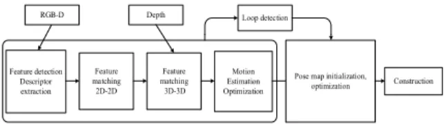
According to the above description, the overall flow of RGB-D SLAM algorithm is shown in Fig. 1.
Feature detection Descriptor extraction
Feature matching 2D-2D
Feature matching 3D-3D
Motion Estimation
Optimization Pose map initialization, Construction optimization
RGB-D Depth Loop detection
Fig. 1. RGB-D SLAM mapping process
4. Key Technologies
The idea of RGB-D SLAM algorithm is to use a limited
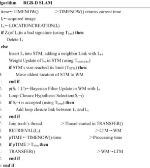
number of locating points in the closed-loop detection, and at the same time to access the entire map locating points when needed, in order to meet the real-time constraints. When the number of locating points in the map makes the time of locating matches exceed a certain threshold, RGB-D SLAM transfers locating points in WM (Working Memory), which are unlikely to form loops, to LTM (Long-Term Memory), so that these transferred locating points do not participate in the next loop detection calculation (Man et al., 2017). When a loop is detected, its adjacent location points can be retrieved from STM (Short-Term Memory) and put back into WM for future loop detection. The principle of the algorithm is shown in Fig. 2 below.
Fig. 2. Principle of RGB-D SLAM algorithm
4.1 Locating Points Generation
The process of locating point generation is shown in Fig.
3. According to the RGB information provided by RGB-D sensor, ORB feature points and their descriptors are extracted and integrated into 3D feature points with corresponding depth information. Based on the epipolar constraint, the basic matrix of 3D feature points matched between two frames is calculated to determine whether the correct matching points (inliers) are enough. On the basis of enough correct matching
points, the position and attitude transformation between the previous frame and the current frame of the interception code-disk odometer is used as the initial estimation of the RGB-D position and attitude transformation of the front and back frames. RANSAC (Random Sampling Consistency) estimation based on PnP (Perspective-n-Point) is carried out for 3-D feature points matched between two frames, and the inter-frame pose is obtained as RGB-D location information (Yu et al., 2017). At the same time, the ORB feature points correspond to a bag of words vector. The above information constitutes the signature St of the current frame, merges St and time stamp t into the location point Lt, initializes the edge of the location point and the previous location point, and sets the weight value to 0, thus completes the processing of the current frame RGB-D and the odometer information stream.
In unknown environments, especially in environments with less features and larger illumination changes, depth information and matching errors of feature points may occur, resulting in the absence of RGB-D positioning information, which will adversely affect the real-time motion control of mobile robot platform. Therefore, it is necessary to fuse the visual positioning information with the codedisk positioning information.
Kinect
RGB
Depth
Feature
points Word bag
vector 3D point set
Motion
chassis Code
odometer Initial estimate Pose estimation Mobile Robot
test platform Location
point Lt
Fig. 3. Generation process of locating points
4.2 Map Construction and Closed-Loop Detection Map construction and closed-loop detection are tightly coupled by graph optimization and memory management methods to ensure the real-time and stability of the mapping process. G2o (General Graph Optimization) graph optimization framework optimizes the similarity and pose relationship of different locating points to ensure global consistency.
According to the similarity of locating points, memory management strategy determines whether it is stored in WM
or LTM. The specific process is shown in Fig. 4. WM stores positioning points with qualified similarity for real-time closed-loop detection. The remaining positioning points are put into LTM as candidate points for closed-loop detection. It is decided to retrieve WM or be rejected according to the size of similarity and the time stored in LTM.
Location
point Graph
optimization Computational similarity s
Pose
calculation Update
memory Loop detection
Indoor 3D map Map revision
Fig. 4. Map construction and closed-loop detection process In order to update the weights of the locating points, Lt is taken as the new vertex of the graph and compared with the last locating point in LTM. Similarity s is measured by (6) (Angeli et al., 2017): Among them, denotes the number of word pairs matched between locating point signatures, while
N and zt Nzc correspond to the total number of words signed between Z and t Z , respectively. If s( , )c Z Z exceeds a fixed t c
similarity threshold Tsimiliarity, the compared location pointsL are fused into c L . In the fused signature, only the t words from Z are saved, while the new words fromc Z are t
deleted from the dictionary: Z is emptied and t Z is copied c
intoZ .t
s(Zt, Zc) = , s( , )
,
pair
zt zc
zt
t c
pair
zt zc
zc
N N
Z Z
N N
≥
<
(5)
According to the similarity s , the conditional probability values of L and other locating points in the graph are t updated to form a closed loop, and the edge weights of Lt
and other locating points in the graph (including the edges of all locating points of WM and LTM) are corrected by g2o. With the change of odometer as the initial estimate, the homogeneous transformation of the location points in L and WM is calculated by ICP algorithm. Because the t
sensor in this paper is the Kinect of RGB-D camera, it can be considered as the pose estimation when the image features are given. The least squares problem can be solved directly by matching known feature points without complex nonlinear optimization. When solving ICP problems, the error term ei
of point pairs is defined as the following Eq.:
( )
i i i
e =p − Rp t′+ (6) By constructing the minimum binary problem, the sum of squares of errors can reach the minimum R,t . The main steps are as follows:
1. Define the centroid p, p′ of two sets of points and calculate the centroid position. The centroid coordinates of each point are represented by the following Eq.:
i i
q = p p− ,qi′= p pi′− (7)′ 2. The rotation matrix is calculated according to the opti- mization objective function:
* '2
1
1 2
n
i i
i
R argmin q Rq
=
= ∑ − (8) 3. According to the rotation matrix of the previous step, the translation vector is calculated:
* '
t = −p Rp (9) According to the calculated rotation matrix and translation vector, the global three-dimensional point cloud map is continuously updated.
5. Experiment and Analysis
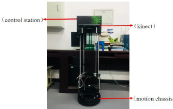
5.1 Experimental Platform
This paper establishes a mobile robot system as shown in Fig. 5 to validate the map building method studied. The system consists of Yujin Kobuki motion chassis, RGB-D sensor (Kinect) and Lenovo g580 mobile computing platform.
Fig. 5. Hardware platform of mobile robot system
Journal of the Korean Society of Surveying, Geodesy, Photogrammetry and Cartography, Vol. 37, No. 2, 45-53, 2019
The proposed method uses the environmental color and depth information obtained by Kinect. The resolution of RGB and depth image is 640×480, the frequency is 30 frames per second, the field of view is 57 degrees horizontally and 43 de- grees vertically, and the depth range in indoor environment is 0.5-5m. In order to avoid image loss during registration, the moving speed of the robot should be kept between 0.1m/s and 0.2m/s, and the rotating speed should be controlled within 1rad/s. The odometer frequency is set to 50 Hz. The CPU of mobile computing platform is i7 7700K, equipped with 16GB running memory. Robot operating system ROS Indigo is in- stalled on this mobile computing platform, and basic toolkits such as OpenCV, Eigen, G2o, PCL and VTK are configured.
5.2 Map Construction Experiments
In order to verify the RGB-D SLAM map building method, the autonomous mobile robot system built in this paper is used to verify the effectiveness of the algorithm in building indoor maps. The related exploratory experiments were carried out in corridors and classrooms by using visual sensors, and the real-time construction of indoor environment was completed.
The experimental results are shown in Fig. 6 below.
(b) (c)
(a)
Fig. 6. Exploration experiment: (a) corridor 1, (b) corridor 2, and (c) classroom
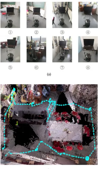
In this paper, representative experiments are conducted in laboratories with complex scenes. Scene settings are shown in Fig. 7(a). Exploration tasks in indoor environments require mobile robots to start mapping and exploring independently from the starting area. If you return to the starting area, the exploration task is completed. The diameter of the mobile robot is 0.5m, including the width of the mobile computing platform, which fully meets the experimental requirements.
Due to the randomness of the exploratory algorithm, mobile
robots explore these scenarios in different order. Therefore, the task of the experiment is to start from the starting area of the laboratory indoor environment and stop exploring when it comes back to the starting area. The 3D point cloud map created by mobile robot autonomous exploration and map building experiment is shown in Fig. 7(b).
(a)
(b)
Fig. 7. Experimental scenarios and results: (a) scene diagram, (b) point cloud map
5.3 Experimental Results and Accuracy Analysis In the process of autonomous mapping and exploration, the 3D point cloud maps of laboratory including narrow aisles, dense obstacle areas and open areas were built in real time by using the odometer information of mobile robot and the
(b) (c)
(b)
Fig. 8. 3D reconstruction effect: (a) 2D image, (b) 3D point cloud
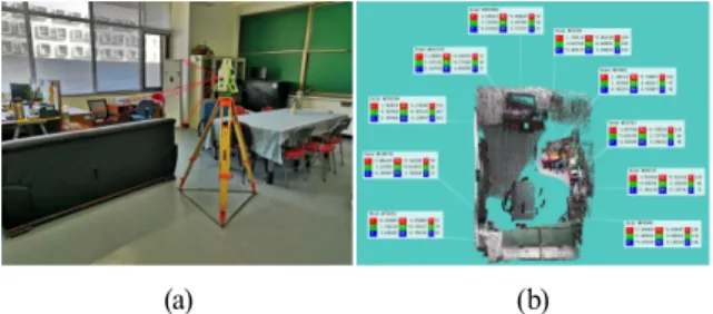
Ten target points are selected as control points in point cloud map for error analysis, and their coordinates are measured by total station. After coordinate transformation, the accuracy of the coordinates is verified with the coordinates selected in SLAM point cloud map. The experimental process is shown in Fig. 9 and Table 1.
RGB-D sensor information. It can be seen that the three- dimensional point cloud map independently established by the mobile robot system can better correspond to the actual indoor environment, the incremental construction of point cloud maps in the process of autonomous exploration of mobile robots can maintain the relative consistency of geometric relations and coherence docking. The effect of feature reconstruction in local map is shown in Fig. 8.
(a)
ID
characteristic point coordinates of
total station characteristic point coordinates of SLAM point cloud
X Y H X Y Z
01 286476.0616 494089.4941 43.0429 1.2081 1.0371 -0.5411
02 286476.0366 494089.8927 43.2177 1.1851 0.6279 -0.3651
03 286474.5239 494092.2262 43.0693 0.4972 -0.6319 -0.3555
04 286473.9435 494091.7402 42.4658 0.5189 -0.6568 -1.0422
05 286473.4152 494091.5997 43.2563 -1.5849 -1.0455 -0.1983
06 286470.2133 494089.1907 43.4933 -4.0405 1.7261 0.0265
07 286471.3652 494087.4496 43.2321 -2.6462 3.1379 -0.3846
08 286476.5599 494084.4241 42.5718 2.8687 4.8879 -1.0890
09 286477.2008 494085.8810 43.6756 3.1545 3.3371 0.0127
10 286477.5944 494086.7923 43.5913 3.1443 2.7240 -0.0160
Table 1. Contrast of coordinates of control points (Unit:m)
(a) (b) Fig. 9. Coordinate acquisition: (a) Total Station Acquisition, (b) SLAM Point Cloud Acquisition In this paper, the accuracy of SLAM point cloud map is evaluated by coordinate transformation of control points.
The distribution of points and errors after coordinate transformation of control points are counted. The experimental results are shown in Fig. 10. The average point position error after coordinate transformation is 0.0045m, which shows that the SLAM algorithm based on vision sensor is feasible for real-time construction of indoor maps.
(a)
(b)
Fig. 10. Coordinate acquisition: (a) Total Station Acquisi- tion, (b) SLAM Point Cloud Acquisition
6. Conclusion
Experiments show that compared with traditional mapping methods, visual SLAM technology reduces the measurement
complexity, does not need a large number of marking points, does not need GPS (Global Positioning System) signals, and is suitable for indoor scenes, and overcomes the limitations of traditional measuring instruments. In this paper, the visual SLAM scheme is applied to the real-time creation of indoor three-dimensional maps using consumer-level depth sensors, and the accuracy of the built indoor maps is evaluated by coordinate transformation. This scheme can solve the problem of real-time construction of indoor maps in surveying and mapping field, because the camera collects a large number of feature points in the course of movement, the efficiency of building three-dimensional point cloud maps is not high. Laser and visual sensors can be used to explore the indoor environment in the later stage, so as to obtain rich and comprehensive environmental information and establish the semantic map of indoor environment.
References
Angeli, A., Filliat, D., and Doncieux, S. (2008), Fast and incremental method for loop-closure detection using bags of visual words, IEEE Transactions on Robotics, Vol. 24, No. 5, pp. 1027-1037.
Endres, F., Hess, J., and Sturm, J. (2017), 3-D mapping with an RGB-D camera, IEEE Transactions on Robotics, Vol.
30, No. 1, pp. 177-187.
Huang, H., Wang. L., and Jiang B. (2016), Accuracy verification of 3D SLAM laser image knapsack surveying robot, Surveying and mapping Bulletin, Vol. 12, No. 5, pp.
68-73.
Man, C. T., Cao, M., and Li, W. (2017), SLAM algorithm evaluation based on depth camera , Journal of Electrical Machinery and Control, Vol. 21, No. 12, pp. 60-65.
Newcombe, R. A., Izadi, S., and Hilliges, O. (2012), KinectFusion: real-time dense surface mapping and tracking, IEEE International Symposium on Mixed and Augmented Reality. IEEE, Vol. 38, No. 6, pp. 127-136.
Nießner, M., Zollhöfe, M., Izadi, S., and Stamminger, M.
(2013), Real-time 3D reconstruction at scale using voxel hashing, Acm Transactions on Graphics, Vol. 32, No.6, pp.
1-11.
Whelan, T., Kaess, M., and Fallon, M. (2012), Kintinuous:
spatially extended KinectFusion, Robotics & Autonomous Systems, Vol. 69, No. 5, pp. 3-14.
Yu, N. B., Wang, S. R., and Xu, C. (2017), A RGB-D based method for autonomous exploration and mapping of unknown indoor environment for mobile robots, Robot, Vol. 39, No. 6, pp. 860-871.