Vol. 14, No. 11 pp. 5385-5391, 2013
Realistic 3D model generation of a real product based on 2D-3D registration
Gang Yeon Kim
1*and Seong Min Son
11Faculty of Mechanical Engineering, Ulsan College
2D-3D 정합기반 실제 제품의 사실적 3D 모델 생성
김강연
1*, 손성민
11울산과학대학교 기계공학부
Abstract As on-line purchases is activated, customers’ demand increases for the realistic and accurate digital information of a product design. In this paper, we propose a practical method that can generate a realistic 3D model of a real product using a 3D geometry obtained by a 3D scanner and its photographic images. In order to register images to the 3D geometry, the camera focal length, the CCD scanning aspect ratio and the transformation matrix between the camera coordinate and the 3D object coordinate must be determined. To perform this 2D-3D registration with consideration of computational complexity, a three-step method is applied, which consists of camera calibration, determination of a temporary optimum translation vector (TOTV) and nonlinear optimization for three rotational angles. A case study for a metallic coated industrial part, of which the colour appearance is hardly obtained by a 3D colour scanner has performed to demonstrate the effectiveness of the proposed method.
요 약 온라인을 기반한 제품의 구매가 활성화 됨에 따라, 소비자들의 제품 디자인에 대한 사실적이고 정확한 정보
를 요구하고 있다. 본 연구에서는 제품의 형상정보(3D mesh)와 색/질감정보(image)를 이용하여 텍스쳐 맵핑된 실사적 3차원 모델을 생성하는 효율적인 방법을 제안한다. 3 차원 형상정보에 대응하는 이미지 상의 텍스쳐 좌표 관계를 구 하기 위해 오브젝트 좌표계와 카메라 좌표계 사이의 변환행렬, 카메라의 초점거리, 카메라 CCD 와 프레임상의 이미 지 사이의 종횡비를 파라미터로 하는 2D-3D 정합을 수행한다. 이러한 2D-3D 정합에 있어 발생하는 연산의 복잡도와 비선형도를 낮추기 위하여, 카메라 내부파라미터 검정단계, 임의의 회전행렬에 대한 임시적 최적 이동 벡터 (TOTV),
회전행렬에 대한 비선형 최적화 단계로 접근한다. 제안하는 방법의 유용성을 시현하기 위해 3차원 컬러 측정기로는
색외관을 획득하기 힘든 메탈릭 페인트 재질로 이루어진 제품에 적용한 구현결과를 보인다.
Key Words : 2D-3D registration, 3D colour scanner, realistic 3D model, texture parameterization
This work was supported by the Research Fund of Ulsan College.
*Corresponding Author : GangYeon Kim(Ulsan College) Tel: +82-52-279-3107 email: [email protected]
Received October 16, 2013 Revised November 5, 2013 Accepted November 7, 2013
1. Introduction
As the E-business such as on-line marketing and on-line purchases is activated, there is an increased demand for the appearance (colour and texture) information of a product as well as its geometry. Since color appearance of a product plays a crucial role in its
commercial success [1]. Several expansive 3D colour scanners are available for acquiring such appearance data and geometrical data of a real object at the same time.
But there are many limitations of measurable materials for the 3D colour scanners. For these reasons, many 2D-3D registration techniques have been suggested to add 2D appearance data such as photographic images to a 3D
object of known geometrical data.
One simple way is selecting a set of points in each image of which corresponding points on the surface are known to solve the 2D-3D relationship[2-3]. From these pairs of points, the relationship between the image view and the 3D object often called camera transformation can be directly determined using standard camera calibration method [4-5]. However, the object should have geometric feature points which can be easily located in the image to find these pairs of points.
Another approach is trying to find the exact camera transformation automatically, using feature points or contours that easily give correspondence between image and geometry (See, Fig 1). But, this kind of algorithm generally requires huge computation to solve high non-linear optimization problem of which unknown parameters are camera focal length, CCD aspect ratio, and position and orientation of the camera [6-10].
[Fig. 1] Overview process of 2D-3D registration
In this paper, we present a practical method of 2D-3D registration that can generate a texture mapped 3D model of a real object. To reduce non-linearity and complexity of 2D-3D registration, a practical approach that separately solves intrinsic parameters and extrinsic parameters of the camera is applied.
2. Camera Transformation
In order to connect 3D geometry and 2D image information, it is required to know the mapping
projected image point in the photographic view. For this work, CCD scanning aspect ratio, the camera focal length and the transformation matrix between the image coordinate and the 3D object coordinate must be determined.
[Fig. 2] The coordinate systems used in our work
As shown in Fig. 2, in our work a simplified Tsai’s camera model is assumed to formulate image-to-object transformation [4].
The mapping relationship between the world coordinate system (Xw, Yw, Zw) and the camera 3D coordinate system (x, y, z) can be formulated by rigid body transformation.
(1)Where, R is a 3x3 rotation matrix, which is determined by using the three rotation angle (θx, θy, θz) and T is a translation vector ∈ R3.
The perspective projected point (uccd, vccd) from a point (x, y, z) on the surface to camera CCD plane (z=f) in the camera coordinate system is given by
(2)Where, f is camera focal length.
Finally, camera CCD coordinate (uccd, vccd) to computer image coordinate (u, v) transformation is given by
∙ ′
∙
′
∙
(3)′
∙
′
∙
Where,
s CCD scanning aspect ratio dx, dy
Size of one CCD cell in x and y direction respectively
Ncx, Ncy
Number of CCD cells in x and y direction respectively
Nfx, Nfy
Number of pixels in u and v direction as sampled by the computer respectively (Cx, Cy) Image coordinate for the origin in the
image plane
3. 3D-2D registration
To perform the 3D-2D registration process robustly, in our work a three step method is applied, which consists of camera calibration for the intrinsic parameters, determination of a temporary optimum translation vector for a certain rotational matrix and nonlinear optimization for the rotational matrix. From (1), (2) and (3), the 3D-2D registration is mathematically described as the optimization of the eight parameters, which are camera focal length f, CCD scanning aspect ratio s, three rotation angles (θx, θy, θz) and translation vector T. In the case of camera intrinsic parameters which are focal length f and aspect ratio s, photographic images of various objects can be easily taken with a fixed value of f and s. So, we can get rid of two complexities by determining internal parameters (f and s) and the other parameters separately.
3.1 Camera calibration
In our work, the method of Tsai’s camera calibration with a calibration pattern is applied to determine internal parameters (f and s) [4]. Figure 3 shows the geometry of our calibration pattern which the matched feature-point sets of (Xw, Yw, Zw) and (u, v) are easily obtained.
[Fig. 3] geometry of camera calibration pattern
At least four feature-point sets are required to solve this camera calibration problem. The singular value decomposition (SVD) for the over-determined case (more than four feature-point sets) is employed[11].
3.2 Nonlinear optimization
To optimize R and T parameters, comparison between the silhouette of the photographic image and the silhouette of a virtually generated image is performed.
The virtual image depends on the R and T parameters. In our work, a segmentation technique of the histogram-based threshold is used to obtain the silhouette of the photographic image [2]. This silhouette comparison can be represented as the cost function J, which is shown below
(4)
′
Where, (i, j) is a spatial index over pixels in an image.
XOR is the ‘exclusive or’ operation. I and I’ denote the binary silhouette image of photographic and virtually generated one respectively.
This optimization problem could be directly solved by numerical method with the approach of the six independent variables (R and T) system but practically it requires too huge computation and often it gives divergent solution. To reduce the complexity and the risk of a local minimum, the temporary optimum translation vector (TOTV) for a certain rotation matrix R is defined. This TOTV can be obtained by the two constraints given by
Rule 1)
The silhouette center positions of I and I’ must be unified.
Rule 2)
The silhouette bounding box size of I and I’ must be equal.
From the rules of 1) and 2), TOTV for a certain rotational matrix R can be expressed as below
(5) ∙
where, O is the origin of camera coordinate, d is the vector from O to The silhouette center positions of I in the CCD Plane(z=f). Q is the silhouette center position of I’. The virtual silhouette image of geometric data is obtained by projecting geometric data to the x-y plane of camera coordinate. C and G is the center position of 3D geometry and G is the projected position of C to the x-y plane of camera coordinate. a and b represent the silhouette bounding box size of I and I’ respectively.
[Fig. 4] The conditions of ‘temporary optimum translation vector’
So, the mathematical model of 3D-2D registration changes J(f, s, R, T) to J(R) or J(θx, θy, θz). The well known Levenberg-Marquardt algorithm of a nonlinear optimization method is employed to determine the optimum value of (θx, θy, θz) that matches the geometry data to its photograph with the lowest error[11].
4. Implementation and Result
(a)
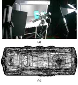
(b) [Fig. 5] 3D geometry acquisition
(a) Our 3D scanning system (b) 3D mesh model of a MP3 player composed of 56,037 vertexes and 10,1944 triangles.
A MP3 player made of shining materials is chosen for a demonstration of the proposed method. 3D points data of the MP3 player is obtained using the 3D scanner of Optoscan HE-100 developed by Breuckman Inc.
Generation of its 3D mesh model from the points cloud data is performed using the Rapidform2004 of a reverse engineering CAD software developed by INUS Technology Inc. In our work OBJ file format which is developed by Wavefront Inc. is chosen to handle a 3D mesh. Figure 5 shows our 3D data acquisition equipment and a captured image of the mesh model composed of 56,037 vertexes and 10,1944 triangles.
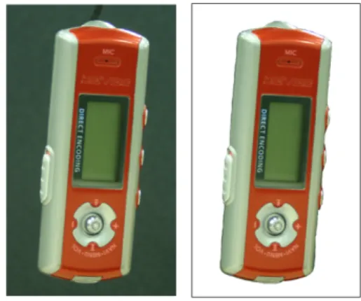
A Cannon Mark II digital camera that produces high resolution image(3504 x 2336 pixels) is used to take photometric images of a product. Figure 6 shows a part of the photometric image of the MP3 player with the resolution of 720 x 1200 pixels and its segmented image.
Figure 7 shows our calibration pattern for estimating the camera focal length. Figure 7 (a) is a real photographical image and Figure 7 (b) is the reconstructed image using the camera inner parameters estimated from Figure 7 (a). Figure 7(c) is the superposed image by overlapping Fig. 7(a) and Fig 7(b).
Figure 8 presents the optimization progress of the 3D-2D registration. To speed up the optimization and even to increase robustness, a reliable initial solution (θx0, θy0, θz0) is determined by user interaction with the mouse.
[Fig. 6] Photographs of the MP3 player: original image (left) and segmented image (right)
(a) (b)
(c)
[Fig. 7] Our camera calibration pattern
(a) Real photograph (b) Reconstructed image from the estimated camera parameters (C) Overlapped image of (a) and (b)
[Fig. 8] Optimization procedure
(a) (b) (c)
[Fig. 9] Error map between the real photograph and the virtually generated image for the registration result
(a) Real photograph (b) Final error map of 2D-3D registration (c) Detail view of the maximum errors
[Fig. 10] A rendering result of a texture mapped 3D model obtained by the proposed method
Figure 9 shows the final error map between the real photograph of a MP3 player and its virtually generated image obtained by the proposed optimizing method.
Errors exist along to the contour of the object, since silhouette based matching is used in our technique. The total number of the mis-matched pixel is 6389 in Fig. (b).
The size of bounding box of the mesh model in the
virtually generated image is 496 x 1023 pixels and the corresponding physical size of the bounding box is 42.3 mm x 87.3 mm. So, the average relative error defined as the number of mis-matched pixels per the number of contour pixels of bounding box is 2.103 and its corresponding physical length is 0.179 mm. And the number of pixels and corresponding physical length for the maximum error as shown in Fig. 9 (c) are 5.09 pixels and 0.436 mm, respectively.
Figure 10 shows some rendering results of the texture mapped 3D model obtained by the proposed method.
5. Conclusion
1. A practical method of 2D-3D registration is developed for generating a realistic 3D model of a real product using 3D geometry obtained by a 3D scanner and its photographic images. The 2D-3D registration is robustly performed by three step approach, which consists of camera calibration, determination of the temporary optimum translation vector and nonlinear optimization for three rotational angles.
2. The effectiveness of the our method is demonstrated by applying to a MP3 Player, of which the colour appearance data is hardly obtained by a 3D colour scanner. Test result shows that our method can be applied with acceptable level of errors for the registration..
3. Our further studies will consider multipe-view to generate a full realistic 3D model.
References
[1] S. S. Suh, C. C. Lee “The Emotional Sensibility Estimation System for Front-load Washer”, J. of the Korea Academia-Industrial cooperation Society, Vol. 11, No.3, pp. 821-826, 2010.
DOI: http://dx.doi.org/10.5762/KAIS.2010.11.3.821 [2] B. Guenter, C. Grimm, D. Wood, H. Malvar, F. Pighin,
“Making Faces”, Proc. of 25th Conference on Computer Graphics and Interactive Techniques, pp. 55-66, July, 1998.
[3] P. E. Debevec, C. J. Taylor, J. Malik, “Modeling and Rendering Architecture from Photographs: A Hybrid Geometry- and Image-based Approach”, Proc. of 23th Conference on Computer Graphics and Interactive Techniques, pp. 11-20, August, 1996.
[4] R. Y. Tsai, “A Versatile Camera Calibration Technique for High-Accuracy 3D Machine Vision Metrology Using Off-the-Shelf TV Cameras and Lenses”, IEEE Journal of Robotics and Automation, Vol. RA-3, No. 4, pp.
221-244, August, 1987.
[5] R. Hou, K. S. Jeong “3D Reconstruction and Self-calibration based on Binocular Stereo Vision”, J. of the Korea Academia-Industrial cooperation Society, Vol.
13, No.9, pp. 3856-3863, 2012.
DOI: http://dx.doi.org/10.5762/KAIS.2012.13.9.3856 [6] D. G. Lowe, “Fitting Parameterized Three-Dimensional
Models to Images”, IEEE Transaction on Pattern Analysis and Machine Intelligence, Vol. 13, No.5, pp.
441-450, May, 1991.
DOI: http://dx.doi.org/10.1109/34.134043
[7] H. P. A. Lench, W. Heidrich, H. P. Seidel, “Automated Texture Registration and Stitching for Real World Models”, Proc. of the 8th Pacific Conference on Computer Graphics and Application, pp. 317-452, October, 2000.
DOI: http://dx.doi.org/10.1109/PCCGA.2000.883955 [8] K. Matsushita, T. Kaneko, “Efficient and Handy Texture
Mapping on 3D Surfaces”, Computer Graphics Forum, Vol. 18, No. 3, pp. 349-358, 1999.
DOI: http://dx.doi.org/10.1111/1467-8659.00355 [9] T. Franken, M. Dellepiane, F. Ganovelli, P. Cignoni, C.
Montani, R. Scopigno, “Minimizing User Intervention in Registering 2D Images to 3D Models”, The Visual Computer, Vol. 21, No. 8-10, pp. 619-628, 2005.
DOI: http://dx.doi.org/10.1007/s00371-005-0309-z [10] M. Corsini, M. Dellepiane, F. Ponchio, R. Scopigno,
“Image-to-Geometry Registration: a mutual Information Method exploiting Illumination-related Geometric Properties”, Computer Graphics Forum, Vol. 28, No. 7, pp. 1755-1764, 2009.
DOI: http://dx.doi.org/10.1111/j.1467-8659.2009.01552.x [11] W. H. Press, S. A. Teukolsky, W. T. Vetterling, B. P.
Flannery, “Numerical Recipes: The Art of Scientific Computing”, 3rd edition Cambridge University Press, 2007.
Gang Yeon Kim
[Regular member]• Aug. 2002 : Gwangju Institute of Science and Technology, Dept. of Mechatronics, MS
• Feb. 2011 : Gwangju Institute of Science and Technology, Dep.
of Mechatronics, PhD
• Jan. 2011 ~ Aug. 2011 : LG Electronics Inc., Inspection &
control system Dept., Senior Research Engineer
• Sep. 2011 ~ current : Ulsan College, Assist. Professor
<Research Interests>
Machine Vision, CAD/CAM, System Operating S/W Development
Seong Min Son
[Regular member]• Feb. 1999 : Pusan National Univ. MS
• Feb. 2004 : Pusan National Univ. PhD
• Nov. 2004 ~ Feb. 2007 : National Univ. of Singapore Research Fellow
• Mar. 2008 ~ current : Ulsan College, Assist. Professor
<Research Interests>
Micro/Non-conventional Machining, Manufacturing