Comparative study on stress distribution around internal tapered connection implants according to fit of cement- and screw-retained prostheses
Mi-Young Lee1, DDS, MSD, Seong-Joo Heo2, DDS, MSD, PhD, Eun-Jin Park1, DDS, MMSc, PhD, Ji-Man Park1*, DDS, MSD, PhD
1Department of Prosthodontics, School of Medicine, Ewha Womans University, Seoul, Republic of Korea
2Department of Prosthodontics, School of Dentistry, Seoul National University, Seoul, Republic of Korea
PURPOSE. The aim of this study was to compare the passivity of implant superstructures by assessing the strain development around the internal tapered connection implants with strain gauges. MATERIALS AND METHODS.
A polyurethane resin block in which two implants were embedded served as a measurement model. Two groups of implant restorations utilized cement-retained design and internal surface of the first group was adjusted until premature contact between the restoration and the abutment completely disappeared. In the second group, only nodules detectable to the naked eye were removed. The third group employed screw-retained design and specimens were generated by computer-aided design/computer-aided manufacturing system (n=10). Four strain gauges were fixed on the measurement model mesially and distally to the implants. The strains developed in each strain gauge were recorded during fixation of specimens. To compare the difference among groups, repeated measures 2-factor analysis was performed at a level of significance of α=.05. RESULTS. The absolute strain values were measured to analyze the magnitude of strain. The mean absolute strain value ranged from 29.53 to 412.94 μm/m at the different strain gauge locations. According to the result of overall comparison, the cement-retained prosthesis groups exhibited significant difference. No significant difference was detected between milled screw-retained prostheses group and cement-retained prosthesis groups. CONCLUSION. Within the limitations of the study, it was concluded that the cement-retained designs do not always exhibit lower levels of stress than screw-retained designs. The internal adjustment of a cement-retained implant restoration is essential to achieve passive fit. [J Adv Prosthodont 2013;5:312-8]
KEY WORDS: Implant prosthesis; Cement retention; Screw retention; Cement space; Passive fit; Strain gauge
INTRODUCTION
In osseointegrated implants, the absence of periodontal space results in limited movement of the implant within the range of 10 μm.1,2 Related to this ankylotic characteristic of implant, the passive fit of superstructure has been considered as a critical factor for the long-term success of implant treatment.3-7
Misfit of the implant-supported prosthesis can cause undesirable strain and consequently lead to biologic compli- cations including harmful load to the bone causing bone loss, and growth of microflora in the implant-restoration gap.8 Also, misfit of a prosthesis can result in mechanical complications such as component fracture and screw loos- ening.9 Screw loosening is not a rare complication10 and causes inconvenience by requiring additional retightening
Corresponding author:
Ji-Man Park
Department of Prosthodontics, School of Medicine, Ewha Womans University, 911-1 Mok-dong, Yangcheon-gu, Seoul, 158-710, Republic of Korea
Tel. 82226505631: e-mail, [email protected]
Received April 19, 2013 / Last Revision August 13, 2013 / Accepted August 16, 2013
© 2013 The Korean Academy of Prosthodontics
This is an Open Access article distributed under the terms of the Creative Commons Attribution Non-Commercial License (http://creativecommons.
org/licenses/by-nc/3.0) which permits unrestricted non-commercial use, distribution, and reproduction in any medium, provided the original work is properly cited.
This work was supported by the Ewha Womans University Research Grant of 2009.
procedure.11,12 Not only the fracture of implant has been reported to occur by many authors,13-15 but it has been observed that the fracture subsequently causes bone loss due to the mobility of the fractured implant body.16 The fracture of fastening screws can also occur and is challeng- ing to recover once it happens.9
It has been reported that every single step in the clinical and laboratory stages can cause errors when manufacturing implant restorations.17 The small errors occurred during the each stage can be accumulated, which will lead to misfit of the implant restoration.18,19
Implant supporting prostheses can be cement-retained or screw-retained. It has been reported that cement-retained design is more favorable in achieving a passive fit. The absence of a screw connection in cement-retained super- structure prevents the strain caused by a misfit from direct- ly impacting the implant by the clamping force.20 On top of that, intervention of a cement layer can compensate for errors.21-23 The cement space is formed during the laborato- ry procedure by applying die-spacer. The resulting cement layer serves as an absorber for the strain22 and helps the equitable transfer of load throughout the bone-implant- restorative system.24-26
The strain gauge has been widely used to measure the strain development around implants.18,19,22,27-33 The strain gauge works based on the fact that an object undergoes deformation as the strain develops. The strain gauge is attached to an object and responds to the deformation of the object under stress. The change in dimension leads to the change in the basic resistance of gauge and that makes it possible to measure the magnitude and direction of the stress. The small size of strain gauges makes them ideal for evaluation of strain development around teeth and prosthe- ses.34
In the present study, the null hypothesis was that even the ill-fitting cement-retained restoration with inadequate cement space would be advantageous in achieving a passive fit, when compared with a screw-retained prosthesis. Thus, the strain development around cement- and screw-retained implant prostheses was measured and evaluated using strain gauges.
MATERIALS AND METHODS
A self-curing polyurethane composite resin (Frame;
Zirkonzahn, Gais, Switzerland) was used to simulate implant-supporting alveolar bone.29 The block was prepared for implant installation by drilling two holes on top of it, and 15 mm apart from each perimeter. Two internal con- nection-type implants with a diameter of 4.1 mm and a length of 10 mm (SSII; Osstem Inc., Seoul, Korea) were installed in the block according to the clinical protocol from manufacturer’s recommendation. The implant was dipped in the mixed polyurethane resin, before it polymer- ized. Each implant was placed into the socket and secured in place with the same resin. Two implants were maintained to be parallel to each other during the installation.
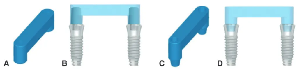
Polymerization of the resin served as osseointegration. The implant fixtures were referred to as implant A and implant B from left to right (Fig. 1). Fixture-level pick-up impres- sion copings (SSICA480; Osstem Inc., Seoul, Korea) were assembled on the fixtures and an impression was taken with a custom tray and a regular-type polyvinylsiloxane impres- sion material (Examixfine; GC, Tokyo, Japan). Implant ana- logs (SSFA480; Osstem Inc., Seoul, Korea) were placed and a vacuum-mixed type IV stone (SynaRock; DFS, Riedenburg, Germany) was poured into the impression to make a work- ing cast. The superstructure was designed as a fixed dental prosthesis with its upper surface flat, providing 3 mm height space underneath the pontic base (Fig. 2). The speci-
Fig. 2. The design for implant superstructure of cement-retained groups (A and B) and screw-retained group (C and D). The upper plane was designed as flat and parallel to the horizontal surface of the resin block.
A B C D
Fig. 1. Measurement model with implant A and B. A polyurethane resin block served as alveolar bone and two implants were placed with an inter-implant distance of 15 mm.
A B15 mm
mens were fabricated on the working cast and adopted cement-retained design as experimental groups and screw- retained design as a control group. The cement-retained group was divided into two groups again, based on whether an internal adjustment was done or not. Each cement- retained group was named as Group Cadj, Group Cnon, res- pectively and the screw-retined group as Group S. Ten specimens were fabricated for each group (Table 1).
To manufacture specimens in the cement-retained groups, two ComOcta cemented abutments (SSCA485;
Osstem Inc., Seoul, Korea) were connected onto the lab analogues in the working cast. After applying two coats of the die-spacer (Rubber Sep; Kerr Corporation, CA, USA), twenty pairs of acrylic resin (Pattern Resin; GC Cor- poration, Tokyo, Japan) copings were fabricated.35 A bar which was made of clear acrylic resin (Jet Acrylic self-cur- ing resin; Lang Dental Mfg Co, IL, USA) with a cross-sec- tion of 4.8 mm × 4 mm was fabricated and a mold was made over this pattern using putty impression material (Twinz; Bisco Inc., IL, USA). Twenty acrylic resin bar repli- cas were manufactured by the mold. Two copings were put on each abutment and linked with the resin bar using wax.
The same procedure was repeated until twenty pairs of copings were connected. The investment, burnout and cast- ing procedures were performed according to the conven- tional lost-wax and casting technique. A Ni-Cr alloy (Vera- Bond II; Aalba Dent Inc., CA, USA) was used for casting.
Ten specimens were selected at random for Group Cadj. The internal surface of the each specimen was examined thoroughly using a silicone material (Fit-checker; GC Corporation, Tokyo, Japan) to detect high spots and pres- sure points. The spots where the silicone peeled away were considered to be premature contacts and were selectively removed using a stone bur. The other ten specimens were classified as Group Cnon and only large nodules apparent to the naked eye were eliminated.
The specimens in Group S were made at computer-aid- ed design/computer-aided manufacturing (CAD/CAM) titanium milling center (Addtech Co. Ltd, Seoul, Korea).
The working cast was placed on an optical scanner (White Light Automatic 3D Scanners; Solutionix DS, Seoul, Korea) to determine the positions and levels of the platforms.
Data on the form of connection parts between abutments and implant fixtures were also imported. After the informa- tion was added to the computer file, the 3D design of the superstructure was completed. In accordance with this design, each framework was milled from one piece of tita- nium block by milling machine (UltraSonic 20 Linear;
DMG, Bielefeld, Germany).
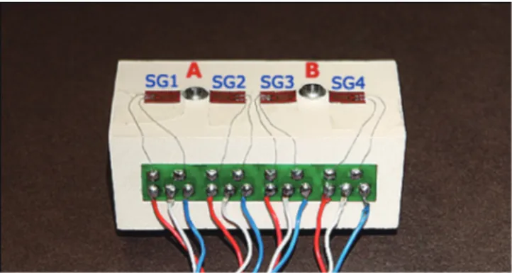
Four strain gauges (KFG-2-350-C1-11; KYOWA elec- tronic instruments, Tokyo, Japan) were attached on the measurement model, mesially and distally adjacent to the implants with an adhesive (M-bond 200; Vishay Micro- Measurements, NC, USA). The strain gauges were referred to as SG1, SG2, SG3 and SG4 from the mesial one of the implant A to the distal one of the implant B (Fig. 3). A dynamic signal conditioning strain amplifier (CTA-1000;
Curiotech Inc., Seoul, Korea) was connected and an analyz- ing program (DA-1700B; Cas Korea, Seoul, Korea) was used to measure and record the strains developed.
Prior to measurement procedure, the measurement model was ensured to be free of residual stress with the strain values showing zero. For the measurement in Group Cadj and Cnon, the ComOcta abutments were assembled onto the implants with a torque of 30 Ncm as the manufacturer’s recommendation. Each specimens were cemented with temporary cement (Temp-Bond; Kerr, MI, USA).20 A defined load of 100 N was applied for 5 and a half minutes to the prostheses using a universal testing machine (5500 series; Instron, MA, USA) atthe middle point of the con- nector between two implants. The direction of loading was perpendicular to the implants. After the specimen was released, it was remained to bench set for few more min- utes. The final strains were recorded until the strain values were stabilized. For the evaluation of Group S, the screw- retained specimens were secured with a driver by an equal sequence. The screws were fastened until resistance was felt and fastening torque was applied until torque wrench set to
Table 1. Abbreviations for different groups investigated
Group Cadj Cement-retained design; cast Ni-Cr metal framework; internal adjustment using Fit-checker Group Cnon Cement-retained design; cast Ni-Cr metal framework; minor internal adjustment
Group S Screw-retained design; milled titanium framework
Fig. 3. The measurement model with strain gauges. Four strain gauges (SG1, SG2, SG3, SG4) were attached with the sensing elements oriented in the mesial-distal direction adjacent to implant A and B.
30 Ncm was folded. The strain values were measured until it was stabilized and the final values were recorded for analysis.
For each group, the stabilized final strain values were collected for the statistical analysis. The measured strain was converted to absolute value for the evaluation. A repeated measures 2-factor analysis was performed for the comparison of the groups, at a level of significance of α=.05 (SPSS 14.0; SPSS Inc., IL, USA). The variance/cova- riance matrix of the dependent variables was evaluated whether they were circular in form.
RESULTS
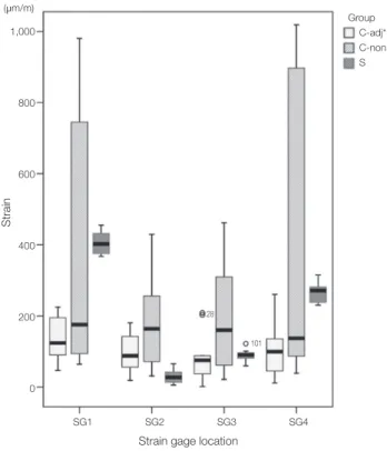
The strain values in μm/m for the three groups and differ- ent strain gauge locations were recorded (Table 2). Mean strain development at the different strain gauge locations ranged from 29.53 to 412.94 μm/m (Table 3). At each gauge location, the average strain was highest in the Group Cnon (Fig. 4). As the Huynh-Feldtepsilon was 0.757 and was to 1, and the repeated contreats were uncorrelated, the sphericity was confirmed for the result of this study.
According to the repeated measures 2 factor analysis, the comparison between Group Cadj and Cnon exhibited signifi- cant difference (P=.008). While the difference was not sig- nificant, the mean strain developed on Group S specimens, a control group, was higher than that of Group Cadj and lower than that of Group Cnon (Table 4).
Table 2. Absolute strain values (μm/m) at the different strain gauge locations
Group Cadj Group Cnon Group S
SG1 SG2 SG3 SG4 SG1 SG2 SG3 SG4 SG1 SG2 SG3 SG4
1 195.0 86.7 71.7 135.5 125.4 141.4 49.3 87.1 416.3 42.1 122.2 231.3
2 46.4 89.3 1.7 55.8 82.4 109.7 162.8 38.6 368.0 52.3 80.9 230.3
3 118.9 56.0 88.3 11.1 980.2 282.7 309.8 898.6 412.9 10.4 91.7 314.9
4 94.0 97.5 79.0 131.4 163.7 186.5 157.0 128.5 375.4 13.4 100.9 281.4
5 90.2 31.9 36.8 45.3 745.1 237.4 285.9 645.1 367.3 65.2 96.1 278.5
6 205.1 63.6 44.6 139.6 967.3 256.2 383.3 1018.5 391.8 34.2 82.1 304.0
7 161.6 180.8 208.7 134 719.6 429.1 461.9 896.8 389.9 22.3 89.0 273.0
8 224.8 149.5 202.9 260.5 64.1 31.0 61.6 77.7 431.7 31.9 59.7 244.1
9 64.1 142.5 85.4 37.5 187.8 71.6 145.1 145.9 454.4 17.9 70.2 238.3
10 129.1 18.6 36.0 67.6 93.8 63.0 21.4 97.2 455.0 5.6 96.1 269.6
Table 3. Mean strain values (μm/m) at each strain gauge location
SG1 SG2 SG3 SG4
Group Cadj 132.92 91.64 85.51 101.83
Group Cnon 412.94 180.86 203.81 403.4
Group S 406.27 29.53 88.89 266.54
Table 4. P values from repeated measures 2 factor analysis (α=.05)
Group Cadj Group Cnon 0.008*
0.177
Group Cnon Group Cadj 0.008*
0.146
Group S Group Cadj 0.177
0.146
*: significant at P<.05
Fig. 4. Boxplot showing the strain values at each strain gauge location. The Group Cnon showed the highest value.
Group C-adj*
C-non S (μm/m)
1,000
800
600
400
200
0
Strain
Strain gage location
* denotes significant difference between group C-adj and C-non SG1 SG2 SG3 SG4
28 101
DISCUSSION
The highest strain was developed around the implants con- nected with the superstructures of Group Cnon. Implant- superstructure complex of Group Cadj was shown to be more passive than that of the other groups. The difference was significant between Group Cadj and Group Cnon. This indicates that an internal adjustment of an implant restora- tion is one of the critical factors to improve a passive fit of the prosthesis. Group Cnon showed higher strain than Group S. While the difference was not significant, this comparison illustrates that cement-retained designs do not always exhibit lower levels of stress than screw-retained designs.
This is opposed to the reports in which several authors have demonstrated that the cement-retained prostheses are advantageous when it comes to passivity.21-26 The magnitude of strain development corresponds to the level of misfit of the restoration.29,36-39 Thus, removing undesirable contacts which can cause misfit is more important to achieve passiv- ity, than selecting the type of retention.
If the misfit is obvious to be felt by the tactile sense, various attempts such as cutting, soldering, or even remak- ing the prosthesis can be done to correct the errors. In this study however, before adjusting the prostheses, every cement-retained specimen was evaluated to fit well without tilting or marginal opening. Therefore, the internal adjust- ments were performed to a very subtle level of correction.
After examining the internal surface using Fit-Checker, only the spots where the Fit-Checker came off were removed selectively. The area near the margin, which had not been covered with the die-spacer, was preserved and set aside from adjustments to ensure the specimens in Group Cadj a reasonable amount of retention.
While the difference was not significant, prostheses from Group Cadj were more passive than those of Group S at the strain gauge locations of SG1, SG 3 and SG 4. The screw-retained superstructures in Group S were manufac- tured with the titanium milling technique by the CAD/
CAM system. Although this method skips some procedures
that can lead to a misfit, there still remains the impression and working cast fabrication procedure which could cause some errors. One of the shortcomings of the screw- retained type was its inability to adjust the prostheses dur- ing the delivery procedure.
When the screw is tightened, a compressive stress is inevitably generated and transmitted to the surrounding alveolar bone, in order to secure the abutment with the implant.40 In this study, Group S revealed particularly high mean strain values at SG1. During the procedure of the measurement model fabrication, the holes for implant fix- tures were drilled by hand without the help of a milling machine for the purpose of reproducing a clinical situation.
Accordingly, the vertical axes of two implants were not per- fectly parallel and the vertical levels of the fixtures were not exactly equivalent. The horizontal part of the superstruc- ture which links the two abutment parts was designed to meet at right angles with the vertical axis of implant B.
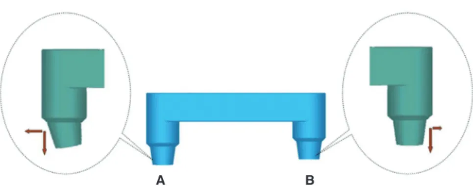
Implant A was anchored at a deeper position and at acute angles to the horizontal axis. Consequently, since the con- nection part of each internal-type screw-retained super- structure was not exactly parallel, the strain developed on each strain gauge was not even. It is assumed that tapered internal surface of implant A might bear the extra com- pression force due to the increased angle between the hori- zontal plane of superstructure and the center line of con- nection part (Fig. 5).
Although the passive fit of an implant prosthesis is regarded as one of the important factors which affect the longevity of an implant treatment,41 the correlation between the mechanical fit of the framework and the bio- logical influence on the surrounding tissue still lacks scien- tific evidences.9,42,43 However, the relationship between strain caused by the misfit and the biologic response of the surrounding tissue could only be discussed, after the in vivo assessment of the strain developmentis established.44 Further clinical studies and cadaver researches is needed to evaluate the strain development in the actual clinical set- tings.
Fig. 5. Illustration for the connection part of screw-retained design. A change in the inclination of the vertical axis could cause the change in the magnitude of horizontal force.
A B
CONCLUSION
Within the limitations of this study presented, the follow- ing conclusions were drawn. The cement-retained designs do not always exhibit lower levels of stress than screw- retained designs. The internal surface adjustment of a cement-retained implant restoration is essential to achieve passive fit.
REFERENCES
1. Rudd KD, O’Leary TJ, Stumf AJ. Horizontal tooth mobility in carefully screened subjects. Periodontology 1964;4:65-70.
2. Sekine H, Komiyama Y, Potta H, Yoshida K. Mobility charac- teristics and tactile sensitivity of osseointegrated fixture-sup- porting systems. In: van Steenberghe D, Albrektsson T, Branemark PI, Henry PJ, Holt R, Liden G editors. Tissue in- tegration in oral and maxillofacial reconstruction. Amsterdam:
Excerpta Medica; 1986. p. 326-9.
3. Adell R, Lekholm U, Rockler B, Brånemark PI. A 15-year study of osseointegrated implants in the treatment of the edentulous jaw. Int J Oral Surg 1981;10:387-416.
4. Lundqvist S, Carlsson GE. Maxillary fixed prostheses on os- seointegrated dental implants. J Prosthet Dent 1983;50:262- 70.
5. Lekholm U, Adell R, Brånemark P-I. Complications. In:
Brånemark P-I, Zarb GA, Albrektsson T, editors. Tissue- Integrated Prostheses: Osseointegration in Clinical Dentistry.
Chicago; Quintessence; 1985. p. 233-40.
6. Rangert B, Jemt T, Jörneus L. Forces and moments on Branemark implants. Int J Oral Maxillofac Implants 1989;4:
241-7.
7. Spector MR, Donovan TE, Nicholls JI. An evaluation of im- pression techniques for osseointegrated implants. J Prosthet Dent 1990;63:444-7.
8. Michalakis KX, Hirayama H, Garefis PD. Cement-retained versus screw-retained implant restorations: a critical review.
Int J Oral Maxillofac Implants 2003;18:719-28.
9. Taylor TD. Prosthodontic problems and limitations associat- ed with osseointegration. J Prosthet Dent 1998;79:74-8.
10. Goodacre CJ, Kan JY, Rungcharassaeng K. Clinical complica- tions of osseointegrated implants. J Prosthet Dent 1999;81:
537-52.
11. Kallus T, Bessing C. Loose gold screws frequently occur in full-arch fixed prostheses supported by osseointegrated im- plants after 5 years. Int J Oral Maxillofac Implants 1994;9:
169-78.
12. Jemt T. Failures and complications in 391 consecutively in- serted fixed prostheses supported by Brånemark implants in edentulous jaws: a study of treatment from the time of pros- thesis placement to the first annual checkup. Int J Oral Maxillofac Implants 1991;6:270-6.
13. Naert I, Quirynen M, van Steenberghe D, Darius P. A study of 589 consecutive implants supporting complete fixed pros- theses. Part II: Prosthetic aspects. J Prosthet Dent 1992;68:
949-56.
14. Adell R, Eriksson B, Lekholm U, Brånemark PI, Jemt T.
Long-term follow-up study of osseointegrated implants in the treatment of totally edentulous jaws. Int J Oral Maxillofac Implants 1990;5:347-59.
15. Jemt T, Book K. Prosthesis misfit and marginal bone loss in edentulous implant patients. Int J Oral Maxillofac Implants 1996;11:620-5.
16. Rangert B, Krogh PH, Langer B, van Roekel N. Bending overload and implant fracture: a retrospective clinical analy- sis. Int J Oral Maxillofac Implants 1995;10:326-34.
17. Tan KB. The clinical significance of distortion in implant prosthodontics: is there such a thing as passive fit? Ann Acad Med Singapore 1995;24:138-57.
18. Heckmann SM, Karl M, Wichmann MG, Winter W, Graef F, Taylor TD. Cement fixation and screw retention: parameters of passive fit. An in vitro study of three-unit implant-sup- ported fixed partial dentures. Clin Oral Implants Res 2004;
15:466-73.
19. Karl M, Winter W, Taylor TD, Heckmann SM. In vitro study on passive fit in implant-supported 5-unit fixed partial den- tures. Int J Oral Maxillofac Implants 2004;19:30-7.
20. Taylor TD, Agar JR, Vogiatzi T. Implant prosthodontics: cur- rent perspective and future directions. Int J Oral Maxillofac Implants 2000;15:66-75.
21. Chiche GJ, Pinault A. Considerations for fabrication of im- plant-supported posterior restorations. Int J Prosthodont 1991;4:37-44.
22. Pietrabissa R, Gionso L, Quaglini V, Di Martino E, Simion M. An in vitro study on compensation of mismatch of screw versus cement-retained implant supported fixed prostheses.
Clin Oral Implants Res 2000;11:448-57.
23. Guichet DL, Caputo AA, Choi H, Sorensen JA. Passivity of fit and marginal opening in screw- or cement-retained im- plant fixed partial denture designs. Int J Oral Maxillofac Implants 2000;15:239-46.
24. Guichet DL. Load transfer in screw- and cement-retained implant fixed partial denture designs [abstract]. J Prosthet Dent 1994;72:631.
25. Misch CE. Screw-retained versus cement-retained implant- supported prostheses. Pract Periodontics Aesthet Dent 1995;
7:15-8.
26. Kim WD, Jacobson Z, Nathanson D. In vitro stress analyses of dental implants supporting screw-retained and cement-re- tained prostheses. Implant Dent 1999;8:141-51.
27. Williams WN, La Pointe LL, Blanton RS. Human discrimina- tion of different bite forces. J Oral Rehabil 1984;11:407-13.
28. Kikuchi M, Korioth TW, Hannam AG. The association among occlusal contacts, clenching effort, and bite force dis- tribution in man. J Dent Res 1997;76:1316-25.
29. Watanabe F, Uno I, Hata Y, Neuendorff G, Kirsch A.
Analysis of stress distribution in a screw-retained implant prosthesis. Int J Oral Maxillofac Implants 2000;15:209-18.
30. Iplikçioğlu H, Akça K, Cehreli MC, Sahin S. Comparison of non-linear finite element stress analysis with in vitro strain gauge measurements on a Morse taper implant. Int J Oral Maxillofac Implants 2003;18:258-65.
31. Karl M, Rosch S, Graef F, Taylor TD, Heckmann SM. Static implant loading caused by as-cast metal and ceramic-ve-
neered superstructures. J Prosthet Dent 2005;93:324-30.
32. Karl M, Wichmann MG, Winter W, Graef F, Taylor TD, Heckmann SM. Influence of fixation mode and superstruc- ture span upon strain development of implant fixed partial dentures. J Prosthodont 2008;17:3-8.
33. Karl M, Wichmann MG, Heckmann SM, Krafft T. Strain de- velopment in 3-unit implant-supported CAD/CAM restora- tions. Int J Oral Maxillofac Implants 2008;23:648-52.
34. Stafford GD, Glantz PO. Intraoral strain gauge measure- ments on complete dentures: a methodological study. J Dent 1991;19:80-4.
35. Bernal G, Okamura M, Muñoz CA. The effects of abutment taper, length and cement type on resistance to dislodgement of cement-retained, implant-supported restorations. J Prosthodont 2003;12:111-5.
36. Clelland NL, Papazoglou E, Carr AB, Gilat A. Comparison of strains transferred to a bone simulant among implant overdenture bars with various levels of misfit. J Prosthodont 1995;4:243-50.
37. Clelland NL, Carr AB, Gilat A. Comparison of strains trans- ferred to a bone simulant between as-cast and postsoldered implant frameworks for a five-implant-supported fixed pros- thesis. J Prosthodont 1996;5:193-200.
38. Clelland NL, van Putten MC. Comparison of strains pro- duced in a bone simulant between conventional cast and res- in-luted implant frameworks. Int J Oral Maxillofac Implants 1997;12:793-9.
39. Pietrabissa R, Contro R, Quaglini V, Soncini M, Gionso L, Simion M. Experimental and computational approach for the evaluation of the biomechanical effects of dental bridge mis- fit. J Biomech 2000;33:1489-95.
40. Nishioka RS, Nishioka LN, Abreu CW, de Vasconcellos LG, Balducci I. Machined and plastic copings in three-element prostheses with different types of implant-abutment joints: a strain gauge comparative analysis. J Appl Oral Sci 2010;18:
225-30.
41. Schwarz MS. Mechanical complications of dental implants.
Clin Oral Implants Res 2000;11:156-8.
42. Jemt T, Book K. Prosthesis misfit and marginal bone loss in edentulous implant patients. Int J Oral Maxillofac Implants 1996;11:620-5.
43. Carr AB, Gerard DA, Larsen PE. The response of bone in primates around unloaded dental implants supporting pros- theses with different levels of fit. J Prosthet Dent 1996;76:
500-9.
44. Eser A, Akça K, Eckert S, Cehreli MC. Nonlinear finite ele- ment analysis versus ex vivo strain gauge measurements on immediately loaded implants. Int J Oral Maxillofac Implants 2009;24:439-46.