한국표면공학회지 J. Korean Inst. Surf. Eng.
Vol. 49, No. 3, 2016.
http://dx.doi.org/10.5695/JKISE.2016.49.3.238
<연구논문>
ISSN 1225-8024(Print) ISSN 2288-8403(Online)
Electrodeposition of Copper on AZ91 Mg Alloy in Cyanide Solution
Nguyen Van Phuong
a, Min-Sik Park
b, Chang Dong Yim
a,c, Bong Sun You
a,c, Sungmo Moon
a,c*aKorea Institute of Materials Science, Gyeongnam 51508, Korea
bKMW Inc., Gyeonggi 18462, Korea
cKorea University of Science and Technology, Daejeon 34113, Korea
(Received June 22, 2016 ; revised June 28, 2016 ; accepted June 29, 2016)
Abstract
Copper electrodeposition on AZ91 Mg alloy was studied in views of preferential deposition on α- or β- phases and how to achieve uniform deposition over the entire surface on α- and β-phases in a cyanide solution.
The inhomogeneous microstructure of AZ91 Mg alloy, particularly α- and β-phases, was found to result in non-uniform deposition of zincate layer, preferential deposition of zincate on β-phases, which leads to non- uniform growth of copper layer during the following electrodeposition process. The preferential depositions of zincate can be attributed to higher cathodic polarizations on the β-phases. Pin-hole defects in the copper electrodeposit were observed at the center of large size β-phase particles which is ascribed to gas bubbles formed at the β-phases. The activation of AZ91 Mg alloy in hydrofluoric acid solution was used to obtain uniform growth of zincate layer on both the α- and β-phases. By choosing an optimum activation time, a uniform zincate layer was obtained on the AZ91 Mg alloy surface and thereby uniform growth of copper was obtained in a cyanide copper electroplating solution.
Keywords : Mg alloy, Copper electrodeposition, Zincate layer
1. Introduction
Mg alloys, as an important family of advanced light metal materials, have been used in many aspects of industrial fields such as aerospace, automobile, electronic and communication equipment recently [1, 2]. One of the main challenges for use of Mg alloys, particularly for outdoor applications, is its poor corrosion resistance [2]. Surface coating techni- ques are applied extensively onto Mg alloys to protect them from corrosion [2-6]. Plasma electrolytic oxidation and anodization treatments are popular processes that significantly improve the corrosion resistance of Mg alloys. Nevertheless, these coatings are generally nonconductive, rough and porous.
Therefore, the fabrication of a metallic layer with low resistivity, good protective capabilities on Mg alloys and electromagnetic shielding property, is gaining interest.
Electrochemical plating, including electro- and electroless plating, has been previously explored on Mg alloys [7-10]. Metallic coatings can impart good surface appearance, and protect Mg alloys from corrosion. Electroless plating has been extensively investigated for Mg alloys [7, 9, 10]. The main advantage of electroless plating is the formation of a uniform coating thickness on complex shaped products. However, its slow deposition rate and the short lifetime of the baths limit more application of this process. The lifetime of electroless bath is seriously shortened when the process is used for Mg alloys due to rapid saturation of the bath with Mg
2+ions due to fast dissolution of Mg into solution.
Additionally, thinner electroless coatings have many micro pin-holes defects, which decrease the corrosion
*
Corresponding Author : Sungmo MoonKorea Institute of Materials Science / Korea University of Science and Technology
Tel : +82-55-280-3549 ; Fax : +82-55-280-3570 E-mail : [email protected]
resistance of coatings on Mg alloys [7, 9]. The electroplating process has also been investigated at length for Mg alloys [7-18]. Disadvantages of electroless plating such as short lifetime of plating baths and slower deposition rate are easily resolved by using electroplating method.
Copper remains the most famous choice for electroplating as it offers many benefits. Copper is a soft and malleable metal, making it an excellent choice for electroplating with other flexible metal materials or objects [19, 20]. Copper plating has very high plating efficiency, excellent coverage even on difficult-to-plate parts, and also, copper is highly conductive. The three basic types of copper electroplating baths are acidic copper bath, alkaline copper cyanide bath and alkaline copper non-cyanide bath such as copper pyrophosphate [19]. The acidic copper bath is most commonly used to electrodeposit copper due to its low-cost, easy to control the deposition process and high deposition efficiencies.
However, the acid solution is not suitable for magnesium alloys due to very fast dissolution of Mg.
Less corrosive and nontoxic copper solution containing pyrophosphate ions, with good throwing power, has been used to deposit copper onto active metals, such as zinc die castings, steel and aluminum [19, 20].
However, magnesium can also react with pyrophosphate ions to form magnesium pyrophosphate complexes dissolvable into the electroplating solution, decreasing the lifetime of the bath. Moreover, copper pyro- phosphate bath is difficult to control. Therefore, the plating of copper on Mg alloys from pyrophosphate solutions has been rarely reported [21, 22]. Alkaline copper cyanide bath, although has high toxicity, is still regarded as a good candidate for copper plating on Mg alloys [19, 22].
Plating of metals onMg alloys is generally carried out in five steps: mechanical cleaning → alkaline
cleaning → acid pickling zincating → electroplating [4, 7, 8]. Pre-treatment process is the most important step for successful electroplating on Mg alloys. Some problems expected to occur during electroplating of copper onto Mg alloys are [7-10]: (1) Mg rapidly reacts with plating solution, releasing Mg
2+ions into the solution, which decreases the life time of the plating bath and lowers the coating quality; (2) the high electrical resistance of magnesium oxide/hydroxide films, which is rapidly formed on the surface, can hinder successful electrodeposition and decrease the adhesion of the coating; (3) the different cathodic polarizations on α-phase and β-phase may result in non-uniform deposition of metal on the surface.
Therefore, to study the electrodeposition behavior of copper on AZ91 Mg alloy is of great interest.
Thus, the purpose of this paper is to study the electrodeposition behavior of copper on AZ91 Mg alloy in views of non-uniform deposition of copper on α- and β-phases in a cyanide solution by controlling the pre-treatment processes. The effects of zincating treatment time and activation time were investigated to find the optimum pretreatment process for a uniform electrodeposition of copper layer on AZ91 Mg alloy.
2. Experimental
The AZ91 Mg alloy with composition (in weight percent) of Al, 8.88; Zn, 0.73; Mn, 0.196; Si < 0.02;
Fe, < 0.01; Cu, < 0.01; Ni, < 0.005; and Mg balance, was used in this study. Samples with a size of 50 mm × 25 mm × 2 mm were cut from an as-cast ingot. The samples were ground in ethanol using SiC abrasive papers successively up to 2000 grit, and then rinsed with ethanol. The bath compositions and operation conditions for deposition of copper are shown in Table 1. An optical microscope (OM, Hirox, Japan) was used to observe the surface and
Table 1. Bath compositions and operation conditions for pretreatments and electrodeposition of copper on AZ91 Mg alloy.Process Bath composition Concentration (M) Condition
(a) SiC-abrasion #2000 grit
(b) Activation HF 0.5 R.T.
(c) Zincating ZnSO4·7H2O 0.2 pH 10.3, 60oC, various times
K4P2O7 0.42
Na2CO3 0.05
KF 0.1
(d) Copper plating CuCN 0.3 pH 12.2, Temp. 55oC,
KCN 0.15 10 mA/cm2
KOH 0.75
cross-sectional morphologies of AZ91 after activation, zincating and copper electroplating. Samples for metallographic examination were prepared by mechanically grinding successively to 2000 grit SiC abrasive paper, followed by finishing with 1 μm diamond paste and then, etched in a solution containing of 19 mL water, 60 mL ethylene glycol, 20 mL acetic acid and 1 mL nitric acid for 30 s.
3. Results and Discussion
Figure 1 displays optical-microscopy images of copper electrodeposited onto the AZ91 plate specimen for various deposition times. The pretreatments used were abrasion by SiC (up to #2000 grit) and zincating treatment for 5 min. Electroplating for 5 min resulted in non-uniform copper deposition and many pores were found at β-phases. The scratch
lines induced by mechanical polishing process were visible, indicating that thin copper coatings were deposited. Increasing the deposition time to 15 min, resulted in the formation of micro pin-holes defects at the β-phases and preferential deposition of copper layer in the β-phases. The size of pin-holes became reduced from 5 ~ 8 µm after 15 min of electroplating to about 1 ~ 3 µm for 30 min of deposition time, and small pin-holes less than 1 µm remained after deposition time of 60 min. The number of pin-holes also decreased with increasing deposition time. The surface morphology obtained after 60 min of deposition was non-uniform, and contained only a few very small pin-holes.
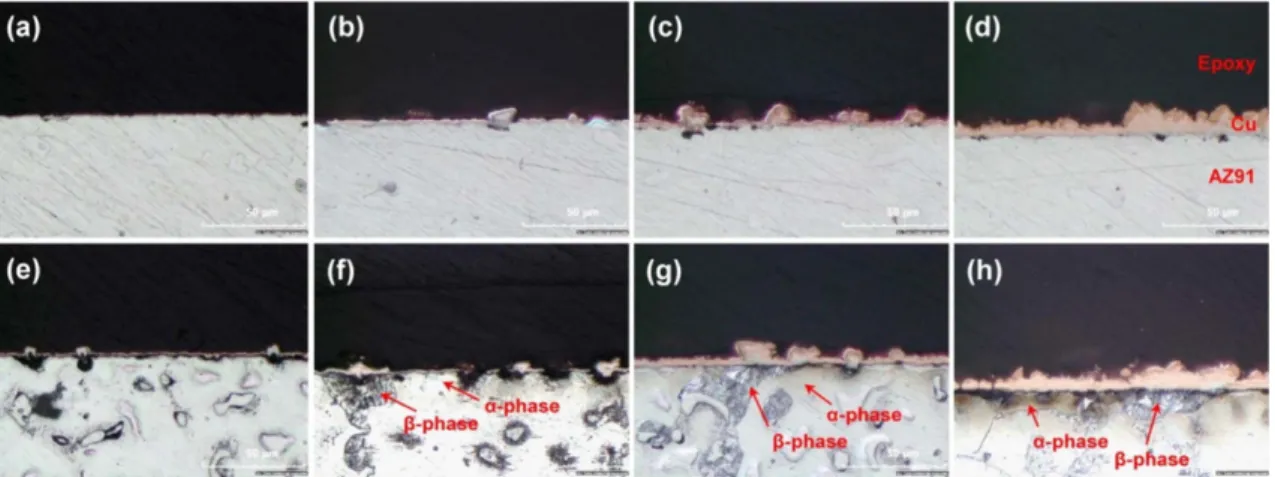
Figure 2 shows cross-sectional views of electro- deposited copper on the AZ91 specimen with various deposition times. The cross-section was etched slightly to show the microstructure of the AZ91 substrate. Figs. 2(e) ~ 2(h) show α- and β-phases of the underlying substrate. Very thin and non- continuous copper layer was deposited on AZ91 surface after 5 min of electroplating. The copper layer almost fully covers the AZ91 surface after more than 15 min of deposition but its thickness was non-uniform. After 60 min of electrodeposition, the thickness of deposited copper layer ranged from 5 to 10 µm. The cross-sectional views of electrodeposited copper layer observed after etching of the polished cross-sections (Figs. 2(e) ~ 2(h)) clearly show a very thick copper layer grown locally on the β-phases and a thin copper layer deposited on the α-phase.
To provide a better understanding of the formation of pin-holes and non-uniform electrodeposition of copper layer, the deposition behavior of copper was observed at the same position of AZ91 Mg alloy
Fig. 1. Optical-microscopy images of electrodepositedcopper on AZ91 after for various deposition times of (a) 5 min, (b) 15 min, (c) 30 min and (d) 60 min.
Fig. 2. Cross-sectional views of electrodeposited copper on AZ91 for various deposition times of (a, e) 5 min, (b, f) 15 min, (c, g) 30 min and (d, h) 60 min. The images were obtained before (a-d) and after (e-f) etching of the polished cross-section by an etchant for 30 s.
sample with electrodeposition time after etching of the polished surface by the etchant solution, as depicted in Fig. 3. The dashed lines drawn on these images were to find the position of β-phases easily.
Spots 1 ~ 6 indicate the positions of the β-Mg
17Al
12phases. After plating for 10 and 30 min (Figs. 3(b) and (c)), the pin-holes were found to be formed at the center of the β-Mg
17Al
12phases (spots 1 ~ 4) while a uniform copper layer was deposited on the α- phase. The deposition rate of copper surrounding the β-Mg
17Al
12phase was higher than that at the α-phase (Figs. 3(b) and (c)). The pin-holes obtained at the smaller β-phases disappeared with increasing deposition time to 30 min (spots 2 ~ 4), while they were still visible at the center of a bigger β-phase (spot 1). The
formation of pin-holes can be ascribed to a masking effect by hydrogen gas bubbles formed on the β- phases during electroplating. The morphologies of electrodeposited layer in Fig. 3 confirmed that the non-uniform growth was due to the different micro- structure of α- and β-phases in AZ91 Mg alloy.
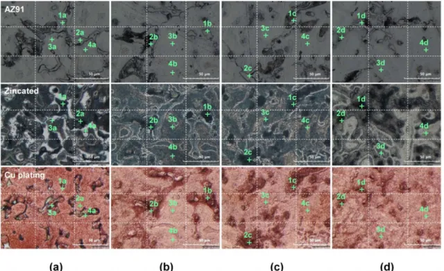
Figure 4 demonstrates effect of zincating time on the deposition of copper on AZ91 Mg alloy in a cyanide copper electroplating solution. The optical- microscopy images of AZ91 Mg alloy were obtained at the same position after acid etching, zincating and copper electroplating for 10 min. Spots 1 and 2 indicate the positions of β-phases and spots 3 and 4 mark the positions of the α-phase. After zincating treatment, all the β-phases became dark, indicating a
Fig. 3. Optical-microscopy images obtained at the same position of AZ91 after (a) etching by etchant solution and (b, c) copper electroplating for 10 and 30 min, respectively.
Fig. 4. Optical-microscopy images of AZ91 obtained at the same position with zincating time after etching by etchant solution (up), zincating treatment (middle) and copper electroplating for 10 min (bottom). The zincating treatment was carried out for (a) 2, (b) 5, (c) 10 and (d) 30 min.
preferential deposition of zinc on the β-phases. For 2 min of zincating treatment time, some bright areas were also obtained (middle of Fig. 4(a)) which corresponds to the positions of α-phase (spots 3a and 4a). No deposits were found at these bright areas during subsequent copper electroplating. With more than 5 min of zincating treatment, the surface of AZ91 was entirely covered with a zincate layer on both the α- and β-phases, as shown by a dark layer.
The deposition of zinc on Mg alloys in a zincating solution can be explained by the following reactions 1 ~ 3 [13,22]:
Mg(OH)
2+ → Mg
2(P
2O
7)
x]
4–x+ 4OH
–(1)
Mg → Mg
2++ 2e
–(2)
Zn
2++ 2e
–→ Zn (3)
For AZ91 Mg alloy, the microstructure is inho- mogenous with the primary α-Mg and the secondary β-Mg
17Al
12phases. Open-circuit potential of the α- phase (–1.6 V
SHE) is more negative than that of the β- phase (–1.3 V
SHE). Therefore, during the zincating treatment, the α-phase acts as an anodic site where preferential dissolution of Mg occurs while the β- phase acts as a cathodic site, where precipitation of zinc dominates. Zinc was found to initially deposit on the β-phase rather than on the α-phase. This result contradicts with the conclusion in another study [16],
where it was reported that the deposition of zinc mainly occurred at the α-phase of AZ91 Mg alloy.
Non-uniform deposition of zinc on AZ91 Mg alloy during zincating treatment leads to non-uniform copper deposition during the subsequent copper electroplating. It should be noted that zincating treatment forms a conductive zinc layer on the magnesium surface which prevents the formation of Mg(OH)
2insulator film. The conductive layer helps the deposition of copper and also results in a good bonding between the metallic substrate and copper plating layer [7, 9, 16]. Thus, if the zincate layer does not fully cover the α-phase, areas with no copper deposition could remain, as can be seen in Fig. 4(a) for the short zincating time of 2 min. In this work, more than 5 min of zincating time is recommended to cover the whole surface of AZ91 including α- and β-phases.
To obtain a uniformly deposited zincate layer, it is important to create an equipotentialized film on the surface of AZ91 Mg alloy before zincating process.
In this work, the AZ91 Mg alloy surface was activated by immersing in hydrofluoric acid solution (HF). In HF solution, the dissolution rate of α-phase is slow due to the formation of stable MgF
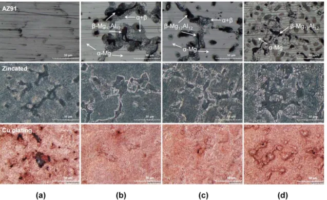
2film over the α-phase, while that of β-phase is fast because Al in the β-phase can form soluble ions. Fig. 5 shows optical-microscopy images of xP
2O
74−AlF
63−Fig. 5. Optical-microscopy images of AZ91 after various activation times of (a) 0 s, (b) 30 s, (c) 60 s, (d) 120s in 0.5 M HF solution, 10 min zincating treatment and 10 min copper electroplating.
AZ91 Mg alloy after various activation times from 0 to 120 s in 0.5 M HF solution, after 10 min zincating treatment and after 10 min copper electrodeposition.
Scratch lines induced during the mechanical polishing step by SiC papers were visible on the abraded AZ91 surface (Fig. 5(a)). On the other hand, the surface activated for 30 and 60 s in the HF solution reveals a typical microstructure of AZ91 Mg alloy with primary α-Mg phase (bright color), the secondary β-Mg
17Al
12phase (dark color) and the lamellar eutectic α+β mixture (Figs. 5(b) and 5(c)).
The obtained microstructure is explained to be formed by different dissolution rates of α- and β- phases in the HF solution. Increasing the activation time to 120 s, produces a cracked layer on the surface, which is explained by the formation of a thick MgF
2film on AZ91 surface. After zincating treatment, zinc layer was uniformly deposited on the whole sample surface, over both α- and β-phases, and large pinholes after copper electroplating were only observed on the inactivated sample (Fig. 5(a)).
For activated samples for 30 and 60 s, the electro- deposited copper layer demonstrates a more uniform morphology with a few small pin-holes (Figs. 5(b) and 5(c)). Increasing the activation time to 120 s, again results in non-uniform deposition of both zinc and copper layers. Thus, it is concluded that the AZ91 specimen surface should be activated for an optimum time between 30 and 60 s in 0.5 M HF solution. The formation of a thin MgF
2film, instead of Mg(OH)
2film on α-phases, may accelerate the formation of a conducting layer on the α-phases during the zincating process, which consequently leads to uniform deposition of copper layer.
However, if thick MgF
2films are formed on the α- phases, the formation of a conducting layer is believed rather to be hindered.
4. Conclusion
Copper electrodeposition on AZ91 Mg alloy was studied in views of non-uniform copper electro- deposition behavior on α- and β-phases and how to achieve uniform copper layer over the α- and β- phases in a cyanide solution. It was found that β- phase is the main reason for the non-uniform deposition of zincate layer which induce also non- uniform growth of copper layer during the following electrodeposition process. The depositions of zincate layer and copper layer during the following electroplating process occurred preferentially on the
β-phases, which act as the cathodic sites due to their higher cathodic polarization than that of α-phase.
Pin-hole defects in the copper electrodeposit were also observed at the center of large size β-phase particles which is ascribed to a masking effect by hydrogen gas bubbles formed preferentially at the β- phases. The zincating treatment was crucial in creating a conducting film on AZ91 Mg alloy surface for subsequent copper electrodeposition. The activation of AZ91 Mg alloy in hydrofluoric acid solution employed prior to the zincating treatment, was found to result in the formation of a uniform zincate layer which leads to uniform electrodeposition of copper layer.
Acknowledgements
This research was supported by the World Class 300 R&D projects funded by the Small and Medium Business Administration of Korea (S2318109) and by a research grant from the general research pro- gram from KIMS (PNK4652).
References
[1] Y. Kojima, Project of platform of science and technology for advanced magnesium alloys, Mater.
Trans., 42 (2001) 1154-1159.
[2] G. L. Song, Corrosion prevention of magnesium alloys, Woodhead Publishing Limited, (2013).
[3] N. V. Phuong, K. H. Lee, D. Chang, M. Kim, S. Lee, S. Moon, Zinc phosphate conversion coatings on magnesium alloys – a review, Met.
Mater. Int., 19 (2013) 273-281.
[4] J. E. Gray, B. Luan, Protective coatings on magnesium and its alloys – a critical review, J.
Alloy Compd., 336 (2002) 88-113.
[5] A. Atrens, G. -L. Song, M. Liu, Z. Shi, F. Cao, M.S. Dargusch, Review of recent developments in the field of magnesium corrosion, Adv. Eng.
Mater., 17 (2015) 400-453.
[6] B. R. Fazal, S. Moon, Formation of cerium conversion coatings on AZ31 magnesium alloy, J.
Kor. Inst. Surf. Eng., 49 (2016) 1-13.
[7] X. B. Chen, H. Y. Yang, T. B. Abbott, M. A.
Easton, N. Birbilis, Corrosion-resistance electro- chemical platings on magnesium alloys: A state- of-the-art review, Corrosion, 68 (2011) 518-535.
[8] X. P. Lei, G. Yu, Y. P. Zhu, Z. P. Zhang, X. M.
He, B. N. Hu, Y. Chen, Successful cyanide free plating protocols on magnesium alloys, T. I. Met.
Finish., 88 (2010) 75-80.
[9] F. Czerwinski, Magnesium alloys – Corrosion and surface treatments, InTech, Croatia, (2011) 153- 184.
[10] L. P. Wu, J. J. Zhao, Y. P. Xie, Z. D. Yang, Progress of electroplating and electroless plating on magnesium alloy, Trans. Nonferrous Met. Soc.
China, 20 (2010) 630-637.
[11] C. A. Huang, T. H. Wang, T. Weirich, V. Neubert, A pretreatment with galvanostatic etching for copper electrodeposition on pure magnesium and magnesium alloys in an alkaline copper-sulfate bath, Electrochim. Acta, 53 (2008) 7235-7241.
[12] P. Zhu, L. Y. Wang, G. R. Qian, T. H. Cao, Copper coating electrodeposited directly onto AZ31 magnesium alloy, Anti-Corros. Method. M., 60 (2013) 127-133.
[13] J. Tang, K. Azumi, Effect of copper pretreatment on the zincate process and subsequent copper electrodeposition of AZ31 magnesium alloy, J.
Electrochem. Soc., 158 (2011) D535-D540.
[14] P. Zhu, L. Y. Wang, Y. Chen, M. Zhou, J. Zhou, Electrodeposition of copper coating on AZ31 magnesium alloy, Surf. Eng., 28 (2012) 796–799.
[15] J. C. Ballesteros, E. Chainet, P. Ozil, Y. Meas, G. Trejo, Electrodeposition of copper from non- cyanide alkaline solution containing tartrate, Int.
J. Electrochem. Sci., 6 (2011) 2632-2651.
[16] J. Tang, K. Azumi, Influence of zincate pretreatment on adhesion strength of a copper electroplating
layer on AZ91 D magnesium alloy, Surf. Coat.
Tech., 205 (2011) 3050-3057.
[17] C. A. Huang, Y. H. Yeh, C. K. Lin, C. Y. Hsieh, Copper electrodeposition on a magnesium alloy (AZ80) with a U-Shaped surface, Materials, 7 (2014) 7366-7378.
[18] J. Lee, W. Chung, U. Jung, Y. Kim, Direct nickel electrodeposition on magnesium alloy in pyrophosphate electrolyte, Surf. Coat. Tech., 205 (2011) 4018-4023.
[19] Modern electroplating 5th edition, Mordechay Schlesinger (Editor), Milan Paunovic (Editor), A John Wiley & Sons, Inc., Publication (2010) 33-78.
[20] O. Radovici, Cecilia Vass, I. Solacolu, Some aspects of copper electrodeposition from pyrophosphate electrolytes, Electrodepos. Surface Treat., 2 (1974) 263-273.
[21] J. H. Lee, Y. H. Kim, U. C. Jung, W. S. Chung, Electroplating on magnesium alloy in KF-added pyrophosphate copper bath, Kor. J. Met. Mater., 48 (2010) 218-224.
[22] J. Kato, W. Urushihara, T. Nakayama, Magnesium based alloys article and a method thereof, US Patent No: 6,068,938.
[23] ASTM standard D3359-02, ASTM International;
2004, 06.01.
[24] Tohru Watanabe, Nano-plating: Microstructure control theory of plated film and data base of plated film microstructure, Elsevier (2004).