• 검색 결과가 없습니다.

Characterization of PVDF/PU fibers prepared by electrospinning

N/A
N/A
Protected

Academic year: 2021

Share "Characterization of PVDF/PU fibers prepared by electrospinning"

Copied!
8
0
0

로드 중.... (전체 텍스트 보기)

전체 글

(1)

https://doi.org/10.6111/JKCGCT.2018.28.1.001

Characterization of PVDF/PU fibers prepared by electrospinning

Jeongwon Rho, Deuk Yong Lee

, Myung-Hyun Lee*, Bae-Yeon Kim** and Heeseok Jeong***

Department of Biomedical Engineering, Daelim University, Anyang 13916, Korea

*Energy and Environmental Division, KICET, Jinju 52851, Korea

**Department of Materials Science and Engineering, Incheon National University, Incheon 22012, Korea

***Convergence Institute of Biomedical Engineering and Biomaterials, Seoul National University of Science and Technology, Seoul 01811, Korea

(Received January 3, 2018) (Revised January 18, 2018) (Accepted January 19, 2018)

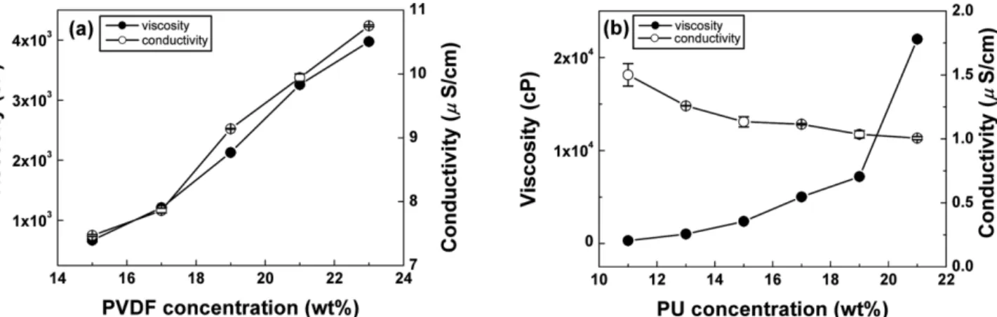
Abstract The 23 wt% polyvinylidene fluoride (PVDF)/15 wt% polyurethane (PU) fibers were electrospun using the conjugated nozzle at a flow rate of 1.0 mL/h and an electric field of 1 kV/cm. The formation of β crystal phase in the PVDF and the PVDF/PU fibers was confirmed by Fourier transform infrared spectroscopy. After electrospinning, the as- spun fibers were immersed in a boiling water and then dried at 100

o

C in a convection oven to make a crimp phenomenon.

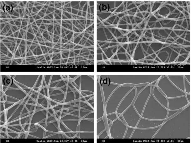
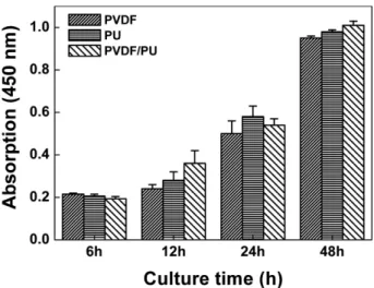
The crimps with a diameter of 2.0 ± 0.08 μm were observed for the PVDF/PU fibers after hydrothermal treatment without sacrificing the extent of β crystal phase. All the PU, PVDF and PVDF/PU fibers exhibited average cell viability of more than 98 %. The cell proliferation results suggested that L-929 cells adhered well to the PU, PVDF and PVDF/PU fibers and proliferated continuously with increasing time, indicating that the PVDF/PU fibers are highly applicable to the biomedical applications.

Key words Polyvinylidene fluoride (PVDF), Polyurethane (PU), Electrospinning, Crimp, Cytotoxicity, Cell proliferation

1. Introduction

Polyvinylidene fluoride (PVDF), a semi-crystalline poly- mer with -(CF

2

-CH

2

)- repeating units, has been consid- ered as the material of choice for electrical devices and systems such as piezoelectric sensors, electro-mechani- cal actuators and energy harvesters [1-7]. Among five different crystalline forms ( α, β, ρ, δ, and ε) of PVDF polymer, the β crystal phase is the most important phase of PVDF. It is noted that the β crystal phase possessing the trans-type molecular chains provide the permanent dipoles arranged in the same direction, leading to large spontaneous polarization [1]. Although the dipole moments in the α phase have a random orientation and result in a nonpolar crystal, the α phase can be converted into β phase with an aid of crystallization from melt, drawing of PVDF films, thermal treatment for 3 h at 130

o

C under vacuum, and poling under high electric field [1- 7]. A flexible PVDF films may overcome the limitation of rigid ceramic sensors and can be used as a wearable sensor as well as a micro-energy harvester. The use of PVDF active sensors is also suitable for the biomedical applications such as the health monitoring methods due

to their biocompatibility and piezoelectric property. The PVDF, a scaffold for bone tissue engineering, can gener- ate electrical activity when mechanically deformed due to the presence of the piezoelectric β-phase [7].

The fabrication of the piezoelectric devices using elec- trospun PVDF fibers is a simple, direct and efficient way to obtain the β phase from the α phase without any further process [1, 6, 7]. The electrospun PVDF fibers have excellent specific surface area, which is highly applicable to the piezoelectric sensors and actuators.

However, porous PVDF nanofibrous membrane made it difficult to form the electrodes due to the porosity. It is desirable to blend with different polymers in order to make the electrode surface smooth and continuous, which costs cheaper than those of chemical modifica- tions or synthesis of tailored macromolecules.

Polyurethane (PU) has been widely used in biomedi- cal applications due to its biocompatibility and mechani- cal properties. Mechanical properties of PU nanofibrous scaffolds were enhanced with increasing the PU concen- tration due to the formation of point-bonding area and supramolecular structure [8]. Point bonding is a form in which the fibers join as if they were welded, and plays an important role in increasing the strength by bearing the load in the tensile test [8]. PVDF and PU nanofi- bers were optimized as a function of polymer content,

Corresponding author

E-mail: [email protected]

(2)

respectively. When the polymers (PVDF and PU) were electrospun in a side-by-side form using a conjugated nozzle (Fig. 1) and subsequently treated hydrothermally in a boiling water, a crimp phenomenon occurred due to the difference in thermal shrinkage between PVDF and PU [1]. In the present study, the PU, PVDF and PVDF/

PU fibers were prepared by electrospinning and opti- mized as a function of polymer concentration. The crimp behavior and the biocompatibility of the PVDF/PU fibers were then examined.

2. Materials and Methods 2.1. Materials

PVDF (polyvinylidene fluoride, Mw = 534,000) and PU (poly[4,4 '-methylenebis(phenyl isocyanate)-alt-1,4- butanediol/di(propylene glycol)/polycaprolactone]) were purchased from Sigma-Aldrich. Dissolving solvents of DMF (N,N-dimethylformamide, Duksan, Korea) and acetone (99.5 %, Samchun, Korea) were purchased and used as received without any further purification. The PVDF (15~23 wt%) and the PU (11~19 wt%) are dis- solved for 6 h at room temperature in DMF/acetone sol- vent mixture (7/3 w/w) and DMF/acetone solvent mixture (6/4 w/w), respectively. The viscosity and the electrical conductivity of solutions were examined by using the viscometer (DV 1M, Brookfield, USA) with spindle NO.

SC4-31 at 30 rpm and the conductivity meter (Metrohm 912, Switzerland).

2.2. Electrospinning

The electrospinning apparatus consisted of two syringe pumps (KDS-200, Stoelting Co., USA), two 21 gage

boiling water for 1 h and dried for 1 h at 100

o

C in a convection oven. When the hot air drying was carried out, it hanged dry so as not to interfere with the shrink- age. The PVDF, PU and PVDF/PU scaffolds were examined by using SEM (S-3000H, Hitachi, Japan) and optical microscopy (SV-55, Sometech, Korea) to investi- gate the morphology of the scaffolds.

2.3. Cytotoxicity

The extract test method was conducted on the PVDF/

PU scaffolds to evaluate the potential of cytotoxicity on the base of the International Organization for Standard- ization (ISO 10993-5) [8-13]. The fibers were extracted aseptically in single strength Minimum Essential Medium (1X MEM, Dulbecco’s Modified Eagles’s Medium (Gibco) with 10 % fetal bovine serum (Gibco) and 1 % penicillin-streptomysin) with serum. The ratio of the nanofibrous films to extraction vehicle was 1.25 cm

2

/ mL. The 96-well plate was incubated at a temperature of 37

o

C in a 5 % CO

2

atmosphere. The test extracts were maintained in an incubator for 24 h. The test extracts were placed onto three separate confluent monolayers of L-929 (NCTC Clone 929, ATCC, USA) mouse fibro- blast cells propagated in 5 % CO

2

. For this test, conflu- ent monolayer cells were trypsinized and seeded in 10 cm

2

wells (35 mm dishes) with a micropipette. Simul- taneously, triplicates of reagent control, negative control (high density polyethylene film, RM-C), and positive control (polyurethane film, RM-A) were placed onto the confluent L-929 monolayers. All monolayers were incu- bated for 48 h at 37

o

C in the presence of 5 % CO

2

. After incubation, the morphological change of the cell was examined to assess the biological reaction by using the inverted microscope (TS100-F, Nikon, Japan) and the iMark microplate absorbance spectrophotometer (Bio- Rad, USA) [8]. Water-soluble tetrazolium salts (WSTs) are a series of other water-soluble dyes for MTT assays, which can provide different absorption spectra of the Fig. 1. A photograph of electrospinning apparatus using a

conjugated nozzle.

(3)

Fig. 2. The variation of viscosity and conductivity as functions of (a) PVDF and (b) PU concentrations.

Fig. 3. SEM images of the PVDF fibers having a PVDF concentration of (a) 15 wt%, (b) 17 wt%, (c) 19 wt%, (d) 21 wt% and (e)

23 wt%.

(4)

Fig. 4. SEM images of the PU fibers having a PU concentration of (a) 11 wt%, (b) 13 wt%, (c) 15 wt% and (d) 17 wt%.

Fig. 5. SEM images of the PVDF/PU fibers as a function of flow rate: (a) 0.5 mL/h, (b) 1.0 mL/h and (c) 1.5 mL/h, respectively.

(5)

formed formazans. EZ-cytox yields a water-soluble for- mazan, which can be read directly. The absorbance of the colored solution is quantified by measuring at a wavelength of 415 nm with the microplate absorbance spectrophotometer [8-13]. The value of untreated cell (control sample, only cultured with culture medium) was set as 100 % and those of the treated cells were expressed as the percentage of the control sample.

2.4. Cell proliferation

Cell counting kit-8 (CCK-8, Dojindo Molecular Tech- nologies, Inc., Japan) was used for the assay of cell pro- liferation. CCK-8, being nonradioactive, allows sensitive colorimetric assays for the determination of the number of viable cells in cell proliferation [8]. WST is reduced by dehydrogenases in cells to give an orange colored product (formazan), which is soluble in the tissue cul- ture medium. The amount of the formazan dye gener- ated by dehydrogenases in cells is directly proportional to the number of living cells. The 96-well plate contain- ing 100 μL of cell suspension (5 × 10

3

cells/well) was incubated for 24 h at a temperature of 37

o

C in a 5%

CO

2

atmosphere. The test extracts (10 μL) were added to the plate and maintained for an appropriate length of time (6, 12, 24, 48 h) in an incubator. After adding 10 μL of CCK-8 solution to each well of the plate, the plate was incubated for 2 h. Then, the absorbance of the colored solution is quantified by measuring at a wave- length of 450 nm with the microplate absorbance spec- trophotometer.

3. Results

The viscosity and the conductivity of the PVDF and

PU solutions are examined and presented in Fig. 2. Vis- cosity provides the time to stay at the tip of nozzle during the electrospinning. If the viscosity of the solu- tion is too low or high, electrospinning would not be possible. Tailored combinations of the viscosity and the conductivity is likely to be necessary for the fiber for- mation. As PVDF and PU concentration increased from 15 wt% to 23 wt% and from 11 wt% to 23 wt%, the vis- cosity increased dramatically from 670 cP to 3.9 × 10

3

cP and from 306 cP to 21.9 × 10

3

cP, respectively. As the viscosity of the PU solution increased, the electrical conductivity decreased from 1.5 μS/cm to 1.0 μS/cm while the conductivity of the PVDF solution increased from 7.4 μS/cm to 10.7 μS/cm.

To determine the optimum combination of viscosity and conductivity, the morphology was examined. The morphology of PVDF and PU fibers electrospun at a flow rate of 0.5 mL/h and an electric field of 1 kV/cm was studied as a function of polymer concentration, as Fig. 6. SEM images of the PVDF/PU fibers (a) before and (b) after the hydrothermal treatment.

Fig. 7. FT-IR spectra of PVDF powder, electrospun PU, PVDF

and PVDF/PU fibers.

(6)

fibers were raised dramatically from 0.7 ± 0.1 μm to 1.9 ± 0.1 μm and 0.7 ± 0.1 μm to 1.0 ± 0.1 μm due to

rate of 1.0 mL/h and at an electric field of 1 kV/cm. After electrospinning, the as-spun fibers were immersed for

Fig. 8. Photographs of cell morphology: (a) positive control, (b) negative control, and the extracts of (c) PU, (d) PVDF and (e)

PVDF/PU membranes from EZ-cytox after exposing with the membrane suspensions for 48 h.

(7)

1 h in a boiling water and then dried for 1 h at 100

o

C in a hot air dryer. During drying, the PVDF/PU nanofi- brous films were hanged and dried so that they could not touch anywhere. SEM images of the fibers before and after the hydrothermal treatment were shown in Fig.

6. The crimp (Fig. 5(b)) formed in a spring shape was observed after hydrothermal treatment [1]. The surfaces of PU and PVDF were smooth and rough, respectively, as demonstrated in Figs. 3 to 5. The diameter of the crimp (2.0 ± 0.08 μm) was almost equal to the sum of the fiber diameters of the smooth PU (0.89 ± 0.04 μm) and the rough PVDF (0.9 ± 0.08 μm) (Fig. 6).

An FT-IR studies of PVDF powder, electrospun PU, PVDF and PVDF/PU fibers, as shown in Fig. 7, revealed that absorption peaks of 510 cm

−1

, 840 cm

−1

and 1278 cm

−1

represented β crystal phase of PVDF. Absorption peaks of 614 cm

−1

, 761 cm

−1

, 796 cm

−1

and 976 cm

−1

corresponded to α crystal phase, which is in good agree- ment with the results reported by Lee et al. [1]. The PVDF powder exhibited a phase mixture of α and β, as shown in Fig. 6. However, absorption peaks of α phase were dramatically attenuated after electrospinning regard- less of the PU addition. On the other hand, the peaks corresponding to β phases became stronger after electro- spinning compared to those of α phases, suggesting that the electrospinning is an effective method for obtaining the β phase. In addition, no difference in FT-IR spectra was detected after hydrothermal treatment, revealing that the crimps produced after hydrothermal treatment did not affect the β phase content of PVDF.

A cytotoxicity test of the PU, PVDF and PVDF/PU films determines whether a product or compound will have a toxic effect on living cells [7, 8]. The test extract with the PU, PVDF and PVDF/PU films showed no evidence of causing cell lysis or toxicity, as depicted in Fig. 8. The PU, PVDF and PVDF/PU films exhibited cell viabilities of 101 %, 98 % and 139 % compared to the negative control, respectively, as measured at a wavelength of 415 nm by using the microplate absor- bance spectrophotometer. The qualitative morphological grading of cytotoxicity of the PU, PVDF and PVDF/PU films was determined to be scale 0. As a result of CCK- 8 cell proliferation experiment [8], L-929 cells adhered well to the PU, PVDF and PVDF/PU films and prolif- erated continuously with increasing time, as depicted in Fig. 9. Therefore, it is conceivable that the PU, PVDF and PVDF/PU films are considered to be clinically safe and effective due to the absence of cytotoxicity and excellent cell proliferation under the condition of this study.

4. Conclusion

PU, PVDF and PVDF/PU fibers were successfully prepared by electrospinning. FT-IR analysis revealed that β crystal phases of PVDF were clearly observed in the PVDF and the PVDF/PU fibers. The diameters of the 15 wt% PU and the 23 wt% PVDF were 1.0 ± 0.1 μm and 1.9 ± 0.1 μm, respectively. The crimps with a diameter of 2.0 ± 0.08 μm were observed for the PVDF/

PU fibers after hydrothermal treatment without sacrific- ing the extent of β crystal phase. All the PU, PVDF and PVDF/PU fibers exhibited average cell viability of more than 98 %. The cell proliferation results suggested that L-929 cells adhered well to the PU, PVDF and PVDF/

PU fibers and proliferated continuously with increasing time, indicating that the PVDF/PU fibers are likely to be highly applicable to the biomedical applications.

References

[ 1 ] H.J. Lee, T.M. Hong, S.C. Lim, J.S. Won and S.G. Lee,

“Preparation and characterization of PVDF/PU bicom- ponent nanofiber by electrospinning”, Textile Sci. Eng.

52 (2015) 88.

[ 2 ] C. Pan, C. Yen, S. Wang, Y. Lai, L. Lin, J.C. Huang and S. Kuo, “Near-field electrospinning enhances the energy harvesting of hollow PVDF piezoelectric fibers”, RSC Adv. 5 (2015) 85073.

[ 3 ] K. Jeong and S. Kim, “Characterization of the PVDF fibers fabricated by hybrid wet spinning”, Compos. Res.

29 (2016) 145.

[ 4 ] E. Nilsson, A. Lund, C. Jonasson, C. Johansson and B.

Hagstrom, “Poling and characterization of piezoelectric polymer fibers for use in textile sensors”, Sens. Actua- tors A 201 (2013) 477.

Fig. 9. Proliferation of L-929 cells on the PU, PVDF and

PVDF/PU nanofibrous films.

(8)

teristics of PU/PEG hybrid scaffolds prepared by elec- trospinning”, J. Biomed. Eng. Res. 38 (2017) 248.

[ 9 ] J.T. Kim, D.Y. Lee, T. Kim, M. Lee and N. Cho, “Bio- compatibility of hyaluronic acid hydrogel prepared by porous hyaluronic acid microbead”, Met. Mater. Intl. 20

[13] C. Chun, D.Y. Lee, J. Kim, M. Kwon, Y. Kim and S.

Kim, “Effect of molecular weight of hyaluronic acid on

viscoelastic and particle texturing feel properties of HA

dermal biphasic fillers”, Biomater. Res. 20 (2016) 275.

수치

Fig. 2. The variation of viscosity and conductivity as functions of (a) PVDF and (b) PU concentrations.
Fig. 4. SEM images of the PU fibers having a PU concentration of (a) 11 wt%, (b) 13 wt%, (c) 15 wt% and (d) 17 wt%.
Fig. 7. FT-IR spectra of PVDF powder, electrospun PU, PVDF and PVDF/PU fibers.
Fig. 8. Photographs of cell morphology: (a) positive control, (b) negative control, and the extracts of (c) PU, (d) PVDF and (e) PVDF/PU membranes from EZ-cytox after exposing with the membrane suspensions for 48 h.
+2

참조

관련 문서

Third, the results of examining the correlation between music interest and psychological well-being showed that the psychological well-being is obtained more firmly by

7) BRUNENGO-BASSO, L'émergence de l'action de groupe, processus de fertilisation croisée, préf. PRIETO, 2011, PU Aix- Marseille, no 274; 이 문헌에 대한 소개는

Recombinant RapA fused with the C-terminus of RapC completely recovered the phenotypes of rapC null cells, indicating that the functions of RapA were modified to become

SEM micrographs of electrospun fibers fabricated with two different collector speeds (CS) for the (a) normal electrospinning process, (b) modified electrospinning process with

Visual Perceptual Development Remedial Activities, Computer, Constructional Block Pu zzle, Pegboard, Plastic card, Card holder. 치료 테이블, 치료 도구 진열장 책,

These results suggest that the bilobalide inhibits the cell proliferation and induces the apoptotic cell death in FaDu human pharyngeal squamous cell carcinoma via both

Comparison of the acyclovir fluxes across hairless mouse skin and artificial membranes (polyether block amide (PBA) membrane, polyurethane (PU) membrane,

Taken together, these results suggested that latex containing the ficin inhibited the cell growth and induced apoptosis by caspase and Bcl-2 family signaling pathway in