This is an Open-Access article distributed under the terms of the Creative Commons Attribution Non-Commercial License(http://creativecommons.org/licenses/by-nc/3.0) which permits unrestricted non-commercial use, distribution, and reproduction in any medium, provided the original work is properly cited.
Journal of Welding and Joining, Vol.32 No.6(2014) pp41-46
레이저 클래딩 공정 조건이 코발트 합금-텅스텐 카바이드 혼합 코팅층의 균열 발생에 미치는 영향
이 창 민*․박 형 권*․이 창 희*,†
*
한양대학교 신소재공학부
Cracking Susceptibility of Laser Cladding Process with Co-Based Metal Matrix Composite Powders
Changmin Lee*, Hyungkwon Park* and Changhee Lee*
,
†*Division of Materials Science & Engineering, College of Engineering, Hanyang University, Seoul 133-791, Korea
†Corresponding author : [email protected]
(Received August 28, 2014 ; Revised October 21, 2014 ; Accepted October 28, 2014)
Abstract
In this study, cracking susceptibility of laser cladding was investigated according to the processing parameters such as laser power, scan speed and feeding rate with blended powders of stellite#6 and technolase40s (WC+NiCr). The solidification microstructure of clad was composed of Co-based dendrite structures with γ +Cr7C3 eutectic phases at the dendritic boundaries. The crack propagation showed transgranular fracture along dendritic boundaries due to brittle chrome carbide at the eutectic phases. From results of fractography experiments, the fracture surface was typical cleavage brittle fracture in the clad and substrate. The number of clad cracks, caused by a tensile stress after the solidification, increased with increase of laser power, scan speed and feeding rate. Increase of the laser power caused large pores by facilitating WC decarburizing reaction. And the pores affected increase of crack susceptibility. High scan speed caused increment of clad cracks due to thermal stress and WC particle fractures. Also, increase of the feeding rate accompanied an amount of WC particles causing crack initiation and decarburizing reaction.
Key Words : Laser cladding, Cracking, Co-Based alloy, Tungsten carbide, Microstructure
ISSN 1225-6153 Online ISSN 2287-8955
1. 서 론
레이저클래딩 (laser cladding)은 물질의 내마모성 과 내식성 향상을 위해 보편적으로 사용하는 표면처리 기술로써, 자동차, 항공기 등의 엔진 또는 채광 산업, 기계 부품 보수 등에 많이 사용되고 있다
1-3). 이러한 레이저클래딩 기술은 코팅층과 모재 사이의 접합력 (bonding strength)이 기존의 열 용사기술 (HVOF, plasma spray 등)에 비해 매우 우수하며, 국소면적에 정밀한 코팅이 가능하다는 장점을 가지고 있다. 또한, 레이저 출력과 빔 사이즈에 의한 에너지 밀도 조절이
용이하기 때문에 다른 오버레이 용접기술 (overlay welding)에 비해 이종접합 시 모재의 희석률 (dilution) 이 낮아 원하는 코팅층의 특성을 얻기 유리한 공정이다
4-8)
. 일반적으로 내식성 향상을 위해 (Co,Ni,Fe)-Cr 합금 등이 분말, 와이어 형태로 주로 사용되며, 고 내 마모성을 요구하는 분야에서는 carbide, boride 입자를 혼합한 금속 모재 복합재료 (metal matrix composite, MMC)형태의 분말이 주로 사용된다
9,10). 하지만 레이 저클래딩 시 코팅층 내 조대한 균열 (crack)이 발생하 면 코팅층의 기계적 특성이 저하되고, 균열을 통해 내 부에 수분, 산 등이 침투하게 되어 모재의 부식을 일으 키는 원인이 된다.
연 구 논 문
(a)
(b)
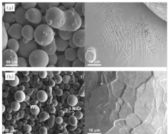
Fig. 1 As-received powders for laser cladding process:
(a) stellite#6, (b) technolase40s
Laser power 900, 1100, 1300 W
Scan speed 5, 8, 11 mm/s
Feeding rate 6, 10, 14 g/min
Beam Size 2.4 mm
Distance 12 mm
Shielding gas (Ar) 15 L/min
Carrier gas (N2) 5 L/min
Stellite#6 + Technolase40s
50 mm
Substrate(stellite#6) 80 mm
60 mm 5 mm
Fig. 2 Schematic image of laser cladding experiments
Table 2 Laser cladding parameters Material Composition (wt%)
Fe W Cr C Co Ni Mn Si
Stellite#6 2.5 5 28 1.2 Bal. 3 1 1 WC
(Technolase40s) <0.1 Bal. 3.9 NiCr
(Technolase40s) 2.8 10.7 <0.6 <0.1 Bal. 2.7 Table 1 Composition of materials used for laser
cladding 레이저클래딩 공정에서 균열은 일반적으로 공정 시 코
팅층 내부에 생성된 잔류응력이 적층물질의 응력 허용 범위를 초과하게 될 경우 발생하게 된다. 잔류응력 발 생은 (1) 응고 중 코팅층의 상부와 하부의 응고속도 차 이, (2) 코팅층과 모재사이의 열팽창계수 차이에 의한 열응력 (thermal stress)이 주요 원인으로 알려져 있 다
11). 또한 MMC형태의 분말을 적층물질로 사용할 경 우, 응고 과정에서 기지금속과 세라믹분말 간의 열팽창 계수 차이가 발생한다. 이로 인해 세라믹 물질이 기지 금속의 수축을 방해하여, 코팅층에 더 높은 잔류응력이 생성됨으로써 균열이 더 쉽게 발생된다고 보고되고 있 다
12-14).
따라서 본 연구에서는 스텔라이트#6 (stellite#6)과 테크노라세40s (technolase40s)혼합 분말을 레이저클 래딩을 통해 적층시켜, 코팅층 내에 발생하는 균열의 발생거동을 분석하였다. 또한 레이저 출력, 조사속도, 분말공급량 등의 공정변수를 변화시키면서 각 공정조건 에 따른 균열의 발생 양상을 관찰하였고, 각 요소들이 균열발생에 미치는 영향을 분석하였다.
2. 실험 방법 2.1 사용 재료
코팅층의 재료는 Fig. 1에서 보는 바와 같이 스텔라이 트#6와 테크노라세40s 분말을 55:45 (wt%)의 비율로 사용하였다. 먼저 스텔라이트#6는 하드페이싱 (hardfacing) 에 주로 이용되는 합금으로써 Table 1에서와 같이 Co 를 기반으로 Cr과 C, W 등으로 이루어져 있으며, 이는 스텔라이트#6가 응고 과정 중 Cr, W 카바이드를 형성함 으로써 내마모성을 향상시키기 위함이다. 스텔라이트#6 분말은 가스분무법 (gas atomization)을 이용하여 제조 되었으며, 공기 중에서 냉각 시 표면적을 최소화하기
위해 Fig. 1(a)과 같이 분말의 형상은 구 형태를 띄게 된다. 본 연구에 사용된 스텔라이트#6의 평균 입도는 45~150 ㎛ 이다. 테크노라세40s 분말은 Fig. 1(b) 에 나타낸 바와 같이 WC 분말과 NiCr 합금 분말이 혼합되어 있고, 혼합비율은 60:40 (wt%)이며, 평균 입도는 40~160 ㎛이다. 이 때, NiCr은 코팅층 형성 시 기지금속 (matrix)으로 작용한다. 본 실험에서는 두 분말을 2시간 동안 쳄버 (chamber)에서 혼합하였 으며, 습기를 제거하기 위해 1시간 정도의 건조과정을 거쳤다.
2.2 레이저클래딩 공정
Fig. 2는 레이저클래딩 실험을 도식적으로 나타낸 것
이다. 레이저는 다이오드레이저 (diode laser)를 사용
하였으며, 레이저 출력 (laser power), 조사속도 (scan
speed), 분말 공급량 (feeding rate)의 세 가지 공정
조건을 변화시켜 실험하였다. 이 때, 레이저 출력은 Table
2에 나타나있는 것과 같이 1100 W를 기준으로 ±200
Thickness 1.2~1.5 mm
Fig. 3 Cross-sectional image of the cladding layer
(a) (b)
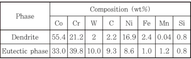
Fig. 4 Microstructure of the matrix : (a) dendrite (g) and eutectic phases, (b) TEM image and SAED pattern of the eutectic phases
Table 3 Results of EDS analysis.
Phase Composition (wt%)
Co Cr W C Ni Fe Mn Si
Dendrite 55.4 21.2 2 2.2 16.9 2.4 0.04 0.8 Eutectic phase 33.0 39.8 10.0 9.3 8.6 1.0 1.2 0.8
(a) (b)
Fig. 5 Morphology of the clad cracks in the (a) coating layer and (b) substrate
W간격으로 설정하였고, 조사속도는 5, 8, 11 mm/s, 분말 공급량은 6, 10, 14 g/min으로 변화를 주었다. 실험은 80 × 60 × 5 mm의 스텔라이트#6 판상 위에 총 4개 의 비드 (bead)를 50% 중첩시켜 지그재그 형태로 클 래딩 하였다. 본 실험에서 보호가스 (shielding gas) 와 이송가스 (carrier gas)는 각각 Ar과 N
2를 사용하 였으며, 레이저 빔의 크기는 2.4 mm, 조사거리 (working distance)는 12 mm로 설정하였다.
레이저클래딩 실험 후, 미세조직 관찰을 위해 시편을 각각 가로, 세로 방향으로 절삭하였고, 연마 (polishing) 후 염산 (HCl), 질산 (HNO
3), 아세트산 (CH
3COOH)를 1:1:1로 혼합한 용액을 이용하여 시편을 에칭 (etching) 하였다. 미세조직은 광학현미경 (optical microscopy, OM, BX60M), 주사전자현미경 (scanning electron microscopy, SEM, SIGMA), 투과전자현미경 (transmi- ssion electron microscopy, TEM, JEM 2010)을 통하여 관찰하였다. 시편의 성분분석에는 에너지 분산 분 광기 (energy dispersive spectroscopy, EDS, Thermo NORAN System 7)를 이용하였다. 또한 코팅층 내 균열을 개방하여 SEM을 통해 파면을 관찰하였다.
3. 결과 및 고찰 3.1 미세구조
Fig. 3은 레이저클래딩 후 코팅층의 단면을 나타낸 것이다. 코팅층의 평균 두께는 평균적으로 1.2~1.5 mm 으로 측정되었으며, 코팅층 내부에는 WC 입자가 고루 분포하고 그 주위를 기지금속이 감싸는 형상을 보였다.
기지금속의 미세조직은 관찰 결과, Fig. 4(a)에 나타나 있는 것과 같이 응고조직인 덴드라이트(γ)와 덴드라이 트 계면 (boundary)의 공정 (eutectic)상으로 구성되 어 있었다. 또한 공정상은 Table 3의 EDS와 TEM 분 석결과로부터 Fig. 4(b)와 같이 γ+Cr
7C
3로 이루어져 있는 것을 확인할 수 있었다. 이러한 공정상은 스텔라
이트 분말의 응고 시 덴드라이트 계면에 Cr이 편석되 면서 다량의 Cr이 C과 반응하여 생성된 것으로 사료된다.
3.2 코팅층 내 균열 거동
균열은 Fig. 5와 같이 일반적으로 코팅층에 수직하게 전파하는 특징을 보이며, 균열 전파 경로 주변에 WC 입자의 파단이 발생한 것을 관찰 하였다. 코팅층 내 균 열은 Fig. 5(a)와 같이 그 폭이 상당히 크며 대체적으 로 입내전파 (transgranular propagation)거동을 보 였다. 그러나 균열의 전파경로 (propagation path)를 관찰한 결과, 균열이 덴드라이트 계면의 공정상을 따라 전파하는 것을 확인하였다. 또한 균열이 모재로 전파할 때 이러한 전파경로를 더 자세히 관찰할 수 있었다.
Fig. 5(b)와 같이 모재의 조직은 코팅층에 비해 상당
히 조대하기 때문에 균열의 전파가 훨씬 용이하며, 균
열은 모재 내의 공정상을 따라 전파하는 특징을 나타내
었다. 이러한 균열이 전파는 공정상 내의 크롬카바이드
가 주요 원인인 것으로 판단된다. 코팅층 내부에 잔류
응력이 발생하게 되면, 균열이 전파할 때 응력에 취약
Coating layer Substrate
Fig. 6 Fracture surfaces of the crack on the coating layer and substrate
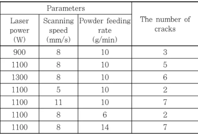
Parameters
The number of cracks Laser
power (W)
Scanning speed (mm/s)
Powder feeding rate (g/min)
900 8 10 3
1100 8 10 5
1300 8 10 6
1100 5 10 2
1100 11 10 7
1100 8 6 2
1100 8 14 7
※ Beam size: 2.4 mm, Distance: 1.2 mm, Shielding gas(Ar): 15 L/min, Carrier gas(N2): 5 L/min
Table 4 The number of cracks according to laser parameters
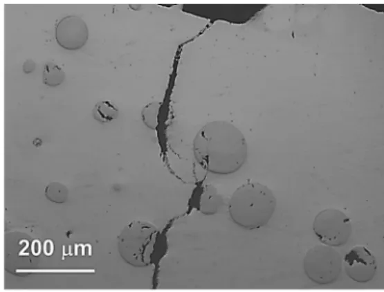
Fig. 7 Optical microgragh of the pores and cracks in the coating layer
한 크롬카바이드가 있는 공정상에서 우선적으로 파단이 발생하게 되는 것이다. 즉, 코팅층과 모재를 통해 전파 하는 균열에 대하여 공정상은 용이한 전파경로로써 작 용하는 것으로 사료된다.
Fig. 6은 균열의 파면관찰 결과를 나타낸 것이다. 관 찰결과, 코팅층과 모재에서 모두 표면이 거칠고 연성이 낮은 파면 형상을 보였는데, 이는 벽개파단 (cleavage fracture)의 일반적인 특징이며, 이로부터 균열이 저온 영역에서 발생한 것으로 판단할 수 있다. 실제로 레이 저클래딩 시 코팅층 내 발생하는 균열은 응고 후 수 초 에서 수십 초 후 발생 하였으며, 이러한 현상은 파면의 형상과 코팅층의 응고속도를 감안할 때, 내부의 조직이 형성 된 후 균열이 발생된 것으로 생각할 수 있다
15). 즉, 코팅층 내 발생한 균열은 저온균열의 특징을 나타 내었으며, 이러한 균열은 응고 후 코팅층 내 잔류응력 에 의해 발생하였을 것으로 사료된다.
3.3 공정변수 변화에 따른 균열의 경향성
Table 4는 각 공정변수 변화에 따른 코팅층 내 균열 의 발생 빈도를 나타낸 것이다. Table 4의 결과를 보 면, 레이저 출력, 조사속도, 분말 공급량의 증가에 따라 균열 발생 수가 증가하는 것으로 나타났다. 먼저, 레이
저 출력의 증가는 코팅층 내의 기공 발생과 관련 있다.
용접에서 입열량이 증가할 경우 응고속도가 감소하여 균열 발생 확률이 낮아지는 것이 일반적인데, 본 연구 와 같이 WC 분말을 사용할 경우 고온에서 식 (1), (2) 의 탈탄반응 (decarburizing reaction)에 의한 코팅층 내 기공이 발생하게 된다
16).
→
(1)
→
→
(2) 코팅층 내의 WC는 열 용사 (thermal spray)와 같 이 높은 온도 환경에서 W
2C로 변하면서 탄소가 탈락하 게 되는데, 이러한 탄소가 주변의 산소와 결합하게 되 어 CO
2가스를 생성된다. 이 때, CO
2가스는 코팅층의 빠른 냉각에 의해 내부에 갇히게 되면서 Fig. 7과 같이 내부에 조대한 기공을 형성하게 된다. 이러한 크기의 기공이 코팅층 내부에 존재할 경우, 코팅층의 부피감소 가 발생하게 되고, 감소한 부피에 비례하여 국부적으로 특성이 취약하게 된다. 따라서 균열은 기공 주변에서 발 생하기 쉬워진다. 또한 이러한 기공을 통해 균열이 전파 하면, 응력해소를 위한 균열의 전파길이 (crack length) 가 더 길어지게 된다. 즉, 조대한 기공은 코팅층 내 부 피감소를 발생시켜 특성 저하에 영향을 미치게 되고, 이러한 원인에 의해 균열의 생성과 전파가 용이해지는 것으로 사료된다.
조사속도에 따른 균열 발생의 변화는 Fig. 8과 같이 속도가 증가할수록 균열의 수가 증가하는 양상을 보였다.
이러한 균열의 양상은 레이저클래딩 시 발생하는 코팅
층 내의 열응력과 관련 있다
17). 일반적으로 용접에서
열원의 조사속도가 빠를수록 대상 물질의 응고속도
(cooling rate)가 빨라지게 된다. 이러한 빠른 응고속
도는 코팅층의 상부와 하부에 온도구배를 더 증가시키
(a)
(b)
Fig. 8 Distribution of the clad cracks according to scan speed : (a) laser power: 900 W, scan speed: 5 mm/s, feeding rate: 14 g/min, (b) laser power: 900 W, scan speed: 11 mm/s, feeding rate: 14 g/min
Fig. 9 A microscopic image of the WC particle fracture
(a)
(b)
Fig. 10 Morphology of the coating layers according to feeding rate : (a) 6 g/min, (b) 14 g/min
게 되고, 이로 인해 코팅층 내의 열응력이 상승하게 된 다. 또한 내부의 WC와 같은 세라믹 입자가 존재할 경 우, 금속기지와의 열팽창계수 (thermal expansion coefficient)차이가 크기 때문에, 응고 시 스텔라이트
#6 금속기지의 수축이 WC 입자에 방해를 받게 되어, 내부의 응력은 더 증가하게 된다. 이러한 내부 환경에 서 WC 입자는 낮은 인장강도 (344 MPa)로 인해 Fig. 9와 같이 입자의 파단이 발생하게 된다. WC 내 부에서 발생한 이러한 균열은 금속기지 쪽으로 전파하 게 되고, 코팅층의 균열을 형성하게 된다
18,19). 결과적 으로, 코팅층 내의 균열 발생에 있어서 WC 입자는 주 요인자로써 작용하는 것으로 판단된다.
또한 분말공급량의 상승은 코팅층 내의 WC의 양을 증가시켜 균열의 생성을 촉진시켰으며, 많은 양의 분말공 급에 따른 모재의 입열량 저하로 인해 용융 풀 (molten pool)이 분말을 모두 수용하지 못하는 문제가 발생하였 다. 따라서 Fig. 10과 같이 코팅층 내의 기공도가 커 지고 코팅층의 전반적인 질이 저하되었다. 이러한 코팅 층 내의 균열을 억제하기 위해서는 WC 분말의 양을 요구하는 특성 (내마모성, 내식성) 범위 내에서 최소화 할 필요가 있으며, 분말 량에 따른 레이저 출력의 최적 화가 수반되어야 한다.
4. 결 론
본 연구에서는 스텔라이트#6 Co 기반 합금과 테크노 라세40s (WC+NiCr)분말을 혼합하여, 레이저클래딩 을 실시하였을 때, 코팅층에 나타나는 균열의 생성 거 동 및 조건 변화에 따른 균열의 발생 양상에 대하여 조 사하였다.
1) 코팅층 내 조직은 덴드라이트(γ)와 덴드라이트 계 면 (boundary)의 공정 (eutectic)상으로 구성되어 있었 고, 공정상의 경우 TEM과 EDS 분석 결과, γ+Cr
7C
3의 구조로 이루어져 있었다.
2) 균열은 전반적으로 코팅층에 수직하게 발생하며, 균열의 전파는 코팅층과 모재의 공정 (eutectic)상을 따라 전파하는 양상을 보였다. 또한, 균열의 파면을 관 찰한 결과 균열은 응고가 끝난 후 저온에서 응력에 의 해 발생한 벽계파단의 특징을 나타내었다.
3) 코팅층의 균열은 레이저출력, 조사속도, 분말공급 량의 증가에 따라 발생량이 상승하는 양상을 나타내었 다. 레이저출력의 증가는 WC의 탈탄반응에 코팅층 내 기공 발생을 증가시켜, 균열을 야기시켰으며, 조사속도 의 증가는 빠른 응고속도에 의한 내부의 열응력 증가로 WC의 파단을 일으켜 균열의 발생을 촉진시켰다. 또한 분말 공급량은 WC 입자의 양을 증가시키고, 모재로 도 달하는 입열량을 감소시켜, 균열 생성뿐 아니라, 코팅 층의 질을 저하시키는 특징을 나타내었다.
5. 감사의 글
이 논문은 한양대학교 교내연구지원사업으로 연구되 었음(HY-2012년도).
Reference