A STUDY ON THE ENGINE PERFORMANCE OF A SPARK A STUDY ON THE ENGINE PERFORMANCE OF A SPARK A STUDY ON THE ENGINE PERFORMANCE OF A SPARK A STUDY ON THE ENGINE PERFORMANCE OF A SPARK IGNITION ENGINE ACCORDING TO THE IGNITION ENERGY IGNITION ENGINE ACCORDING TO THE IGNITION ENERGY IGNITION ENGINE ACCORDING TO THE IGNITION ENERGY IGNITION ENGINE ACCORDING TO THE IGNITION ENERGY
Sung Bin Han
Department of Mechanical & Automotive Engineering, Induk University (Received 12 May 2014, Revised 16 June 2014, Accepted 18 June 2014)
Abstract
The more or less homogeneous fuel-air mixture that exists at the end of the compression process is ignited by an electric ignition spark from a spark plug shortly before top dead center. The actual moment of ignition is an optimization parameter; it is adapted to the engine operation so that an optimum combustion process is obtained. Brake mean effective pressure (BMEP) of the spark ignition energy control device (IECD) than conventional spark system at the stoichiometric mixture is increased about 9%. For lean burn engine, the lean limit is extended about 25% by using the IECD. It was considered the stability of combustion by the increase of flame kernel according to the high ignition energy supplies in initial period and discharge energy period lengthen by using the IECD.
Key words : Engine performance, Brake mean effective pressure (BMEP), ignition energy control device (IECD), Lean limit
1. INTRODUCTION
The development of automobiles with heat engines is one of the greatest achievements of modern technology. However, the highly developed automotive industry and the large number of automobiles in use around the world have caused and are still causing serious problems for society and human life. Deterioration in air quality, global warming, and a decrease in petroleum resources are becoming the major threats to human beings. More and more stringent emissions and fuel consumption regulations are stimulating an interest in the development of safe, clean, and high-efficiency transportation.
It has been well recognized that electric, hybrid electric, and fuel cell-powered drive train technologies are the most promising solutions to the
problem of land transportation in the future [1].
A number of automobiles on the market obtain high fuel efficiency by the use of lean-burn engines. By using a stratified charge, these engines obtain efficient combustion with overall air-fuel ratios of 21. Figure 9-7 shows that normal catalytic converters will work in reducing HC and CO at lean conditions but are very inefficient at reducing NOx. Special converters, which use platinum and rhodium combined with alkaline rare earths, have been developed for lean-burn engines. Combustion temperatures must be limited in these engines so that NOx production is kept within manageable limits [2].
To increase operational reliability, ignition systems should have low source impedance and/or a fast voltage rise (shunt resistance). Furthermore, ignition systems must provide sufficiently high voltage. In future ignition systems, we can anticipate a further rise in the demands on available voltage. In particular, the required ignition voltage in a lean-running engine with direct fuel injection http://dx.doi.org/10.5855/ENERGY.2014.23.3.001
To whom corresponding should be addressed.
Department of Mechanical & Automotive Engineering, Induk University 12 Choansan-ro, Nowon-gu, Seoul 139-749, Rep of Korea.
Tel : TEL:+82-2-950-7545 E-mail : [email protected]
to the end of the compression stroke. The high-temperature plasma kernel created by the spark develops into a self-sustaining and propagating flame front. The function of the ignition system is to initiate this flame propagation process, in a repeatable manner cycle-by-cycle, over the full load and speed range of the engine at the appropriate point in the engine cycle [4].
Understanding of flame initiation is important not only for fundamental combustion research but also for fire safety control and the development of low-emission gasoline and homogeneous charge compression ignition (HCCI) engines. When an external energy is locally deposited into a combustible mixture, there are four possible outcomes: an evolution from outwardly propagating spherical flame to planar flame; a stationary flame ball; a propagating self-extinguishing flame; or a decaying ignition kernel. The evolution of the flame kernel and the final outcome depends on the magnitude of energy addition, fuel concentration, radiation heat loss and transport and kinetic properties. Efficient flame initiation with minimum energy deposition and successful control of fire spreading highly depend on the understanding of the correlations between ignition kernels, flame balls, self-extinguishing flames and propagating spherical and planar flames, as well as the impacts of radiation intensity and the transport properties on the flame regime transitions [5-7].
Randeberg et al.[8] described a spark generator for producing synchronized capacitive spark discharges of low energy, down to below 0.1 mJ.
However, Eckhoff et al. [9] re-examined the
input to the order of 0.25 mJ .
The spark forming at the spark plug can be divided into three sequential types of discharge with very different
energy and plasma physical properties. Initially, the voltage at the spark plug rises sharply. As soon as the current charge forming in the field reaches the opposing electrode, breakdown occurs within a few nanoseconds. The impedance of the electrode path falls drastically, and the current rises quickly from the discharge of the leakage capacitance of the spark plug [3].
In a conventional spark-ignition engine the fuel and air are mixed together in the intake system, inducted through the intake valve into the cylinder, where mixing with residual gas takes place, and then compressed. Under normal operating conditions, combustion is initiated towards the end of the compression stroke at the spark plug by an electric discharge. Following inflammation, a turbulent flame develops, propagates through this essentially premixed fuel, air, burned gas mixture until it reaches the combustion chamber walls, and then extinguishes [4]. This paper investigates the effect of performance from a spark ignition engine according to the multi spark ignition energy control device.
2. EXPERIMENTAL SETUP AND EXPERIMENTS
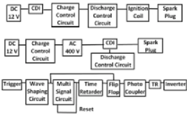
Figure 1 shows the block diagram of the ignition energy control device (IECD). The IECD was consisted of a capacitor discharge igniter, charge
control circuit and discharge control circuit. The capacitor discharge igniter was parallel connected with the capacitor discharge igniter as much as the number of ignited spark. The charge control circuit supplied spark energy to the capacitor discharge igniter, and a discharge control unit supplied energy of the required spark interval and times in spark timing.
The capacitor discharge igniter consisted of the rectifier that could convert the supplied high alternating current voltage from the part of charge control circuit, the condenser that could charge and discharge the ignition energy, and the SCR(1200V,
30A) that could discharge the ignition energy of condenser by trigger pulse. And the ignition coil used was that a conventional spark ignition engine used [10]. The energy is charged in a capacitor discharge igniter that copes with the high speed revolutions, in addition to the followings is that a charge discharge control circuit that to spark with the required spark interval and times in spark timing.
The IECD converts the 12V to the high voltage AC, and charges energy in condenser, and discharges in any time. At this time, the noise occurred by the supplied high voltage in condenser.
The noise operates on the SCR, and has become to break the igniter as well as the control is imperfect.
To solve these problems, it was selected the low voltage type. The charge control circuit consists of wave shaping circuit, multi signal circuit, time retarder, and flip-flop circuit. The wave shaping circuit inputs discharge control circuit and sparks by input of SCR trigger of the capacitor discharge igniter. The simultaneously input signal in time retarder delays the time, 12 DC voltage supplies to DC-AC converter by multi signal circuit and flip-flop circuit, and then occurs an alternating current voltage. And it becomes DC through a primary boosting transformer, charges energy in condenser, and finishes the charge before the first spark.
In order to prevent the occurring noise from DC-AC converter, the photo coupler separated the Fig. 1. Block diagram of the ignition energy control
device (IECD).
Fig. 2. Discharge energy versus number of spark.
Table 1. Spark duration, spark energy and discharge
pattern of spark energy of IECD.
Spark interval,
ms
No.of spark
Cap.
energy, mJ
Ind.
energy, mJ
Total energy,
mJ
Single 1 2.67 0.51 3.18
0.15 2 13.01 0.77 13.77
0.15 4 14.58 1.67 16.25
0.15 6 14.58 3.07 17.65
0.15 8 14.58 4.84 19.42
Single 1 2.67 0.51 3.18
0.20 2 13.01 0.98 13.98
0.20 4 15.40 2.54 17.94
0.20 6 15.40 4.98 20.38
0.20 8 15.40 7.52 22.92
Single 1 2.67 0.51 3.18
0.25 2 13.01 1.63 14.63
0.25 4 16.25 3.66 19.90
0.25 6 16.25 7.34 23.59
0.25 8 16.25 12.08 28.32
control circuit and the power source of capacitor discharge igniter. By this way, IECD could be operated stably. The number of sparks and interval are determined as controlling the width and times that determine the discharge time of the secondary voltage. The pulse intervals are changed by the variable resistance. The number of sparks are controlled by the counter and pulse generating control apparatus. The ignition device, provided the ignition energies of 3.18 mJ to 28.32 mJ as show in Table 1.
Figure 2 shows total discharge energy as a function of number of spark when the spark interval is 0.15 ms, 0.20ms, 0.25ms and number of spark is from single to 8 times. Ignition energy was assumed that the all energy of condenser in store discharge, and the ignition energy determined from,
Total discharge spark ignition energy = inductive discharge energy + capacitive discharge energy.
In Figure 2, the IECD is possible to supply the total discharge spark energy, from the conventional single spark discharge energy, 3.18mJ to (spark interval: 0.25 ms, number of spark: 8 times) 28.32 mJ.
3. RESULTS AND DISCUSSION
Figure 3 shows the schematic diagram of the engine tested. The engine which was spark ignited had a compression ratio of 9.4, 4-cylinder, and a displacement of 1468 cc. The performance was tested by connecting the crank shaft to the dynamometer. An engine control system (IC 5460, INTELLIGENT CONTROLS, INC.) was used to control the fuel injection timing and spark timing.
An air-fuel ratio measurement system (UEGO Sensor, HORIBA 110) was used to measure the air-fuel ratio. The fuel injection timing, air-fuel ratio, spark timing, and spark ignition energy were the experimental operating variables at a part load.
The engine speed is fixed at 2000 rpm. The cooling water temperature is fixed at 80°C. To study the influence of brake mean effective pressure (BMEP) at 2000 rpm with spark ignition energy variables, spark timing is fixed at minimum spark advance for best torque (MBT). A piezo-electric pressure transducer, Kistler 6061B, was mounted in the cylinder head to measure the cylinder pressure. The average cylinder pressure diagram of the 100 consecutive cycles was used to evaluate the stability at 2000 rpm. An absolute pressure sensor (Kistler 4045A2) was used to measure the inlet pressure.
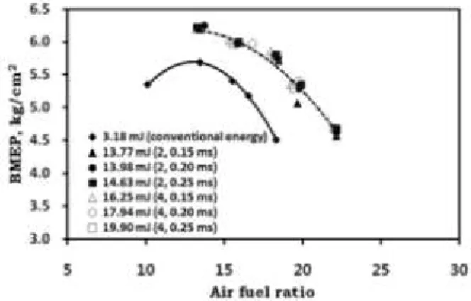
Figure 4 shows the brake mean effective pressure (BMEP) as a function of air fuel ratio according to discharge energy 3.18 mJ (conventional spark
cap ind
total E E
E = +
2 2 2
2 2
1 2
1
d
iI t C V
V +
=
Fig. 3. Experimental setup. Fig. 4. Brake mean effective pressure versus air fuel ratio.
energy), 13.77 mJ (spark interval: 0.15 ms, number of spark: 2 times), 13.98 mJ (spark interval: 0.20 ms, number of spark: 2 times), 14.63 mJ (spark interval: 0.25 ms, number of spark: 2 times), 16.25 mJ (spark interval: 0.15 ms, number of spark: 4 times), 17.94 mJ (spark interval: 0.20 ms, number of spark: 4 times), and 19.90 mJ (spark interval: 0.25 ms, number of spark: 4 times). Figure 15 shows BMEP as a function of air fuel ratio at each ignition method. The spark interval and times were 0.15 ms, 0.20 ms, 0.25 ms, 2 times and 4 times respectively.
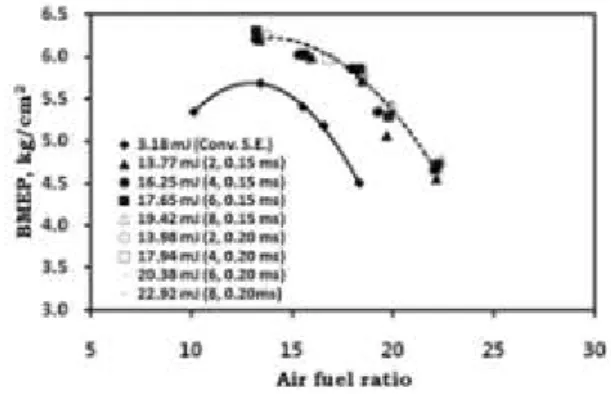
Figure 5 shows the brake mean effective pressure (BMEP) as a function of air fuel ratio according to discharge energy 3.18 mJ (conventional spark energy), 13.77 mJ (spark interval: 0.15 ms, number of spark: 2 times), 16.25 mJ (spark interval: 0.15 ms, number of spark: 4 times), 17.65 mJ (spark interval: 0.15 ms, number of spark: 6 times), 19.42 mJ (spark interval: 0.15 ms, number of spark: 8 times), 13.98 mJ (spark interval: 0.20 ms, number
of spark: 2 times), 17.94 mJ (spark interval: 0.20 ms, number of spark: 4 times), 20.38 mJ (spark interval: 0.20 ms, number of spark: 6 times), and 22.92 mJ (spark interval: 0.20 ms, number of spark:
8 times). Figure 16 shows BMEP as a function of air fuel ratio at each ignition method. The spark interval and times were 0.15 ms, 0.20 ms, 2 times, 4 times, 6 times and 8 times respectively.
Figure 6 shows the brake mean effective pressure (BMEP) as a function of air fuel ratio according to discharge energy 3.18 mJ (conventional spark energy), and from 13.77 mJ to 28.32 mJ (spark interval: 0.15 ms, 0.20 ms, 0.25, number of spark:
2 times, 4 times, 6 times, 8 times). Figure 17 shows BMEP as a function of air fuel ratio at each ignition method. The spark interval and times were 0.15 ms, 0.20 ms, 0.25 ms, 2 times, 4 times, 6 times and 8 times respectively.
As shown in Figures 4, 5 and 6, according to the increase of number of sparks and spark intervals, the BMEP become to increase more than the conventional spark energy system and extend in air fuel ratio of near 22.5. While on the other in the conventional spark energy system, the air fuel ratio is 18. It is considered that is due to the stability of combustion as increase of flame kernel size according as high ignition energy supplies in initial period and discharge energy period lengthen. It is expressed that if the duration period lengthens as ignition energy discharges continuously with IECD, Fig. 5. Brake mean effective pressure versus air fuel ratio. Fig. 6. Brake mean effective pressure versus air fuel ratio.
Table 2. Specification of test engine.
Engine type 4-cylinder, MPI
Bore x stroke 75.5 x 82.0 mm
Clearance volume 43.7 cc
Displacement 1468 cc
(367 c/cylinder)
Injection type Sequence
Compression ratio 9.4
Inlet valve opening (IVO) 18.5°bTDC
Inlet valve closing (IVC) 51.5°aBDC
Exhaust valve opening EVO) 51.5°bBDC
Exhaust valve closing (EVC) 18.5°aTDC
22.5. In addition to the BMEP of the IECD than single spark at the same air-fuel ratio is increased remarkably. For example, the BMEP of the IECD than conventional spark system at the stoichiometric mixture is increased about 9%. By using the IECD for lean burn engine, the air fuel ratio of 18 becomes to be of near 22.5. Therefore it means that the lean limit is extended about 25% by using the IECD.
It was considered the stability of combustion by the increase of flame kernel according to the high ignition energy supplies in initial period and discharge energy period lengthen by using the IECD.
CONCLUSIONS
Based on the results of this study, the following conclusions were observed.
According to the increase of number of sparks and spark intervals, the engine performance become to increase and the expected lean limits are extended. It is considered that is due to the stability of combustion as increase of flame kernel size according as high ignition energy supplies in initial period and discharge energy period lengthen.
The brake mean effective pressure (BMEP) of the ignition energy control device (IECD) than conventional spark system at the stoichiometric mixture is increased about 9%. By using the IECD for lean burn engine, the air fuel ratio of near 18 becomes to be about 22.5. Therefore it means that the lean limit is extended about 25% by using the IECD. It was considered the stability of combustion by the increase of flame kernel according to the high ignition energy supplies in initial period and
3. Basshuysen R. V., Schafer F., Internal combustion engine handbook (Basics, components, systems, and perspectives), SAE International, (2004).
4. Heywood, J. B., Internal Combustion Engine Fundamentals. McGraw-Hill, USA, (1988).
5. Chen, Z., Ju Y., Theoretical analysis of the evolution from ignition kernel to flame ball and planar flame, Combustion Theory and Modelling, Vol 11, No. 3, pp.427-453, (2007).
6. Ko, Y., Anderson, R. W., Arpaci, V. S., Spark ignition of propane-air mixtures near the minimum ignition energy: Part 1. An experimental study. Combustion and Flame, 83, 75-87, (1991).
7. Song, J. and Sunwoo, M. (2001). Flame kernel formation and propagation modeling in spark ignition engines. Proc Instn Mech Engrs 215, 105-114.
8. Randeberg E., Olsen W., Eckhoff R. K., A new method for generation of synchronised capacitive sparks of low energy, Journal of Electrostatics, 64, pp. 263-272, (2006).
9. Eckhoff R. K., Olsen W., Kleppa O., Influence of spark discharge duration on the minimum ignition energy of premixed propane/air, Proc.
7th International Symposium on Hazards, Prevention and Mitigation of Industrial Explosions, (2008).
10. Han, S. B., Choi, K. H., Ra, S. O., Lee, S.
J., Lee, J. T. Ignitability and combustion characteristics of the multi spark capacitor discharge igniter for a lean burn engine. SAE Paper No. 952396, (1995).