This is an Open-Access article distributed under the terms of the Creative Commons Attribution Non-Commercial License (http://creativecommons.org/licenses/
†
*
**
***
전체 글
This is an Open-Access article distributed under the terms of the Creative Commons Attribution Non-Commercial License (http://creativecommons.org/licenses/
†
*
**
***
수치
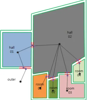
![Figure 2. Structure Space Model[11]](https://thumb-ap.123doks.com/thumbv2/123dokinfo/5119818.333157/5.799.175.617.715.979/figure-structure-space-model.webp)
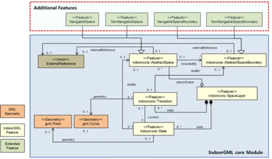
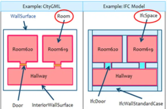
![Figure 3. UML Diagram of Space Relation Model[11]](https://thumb-ap.123doks.com/thumbv2/123dokinfo/5119818.333157/6.799.118.683.98.514/figure-uml-diagram-of-space-relation-model.webp)
관련 문서
The implemented route guidance system follows the Indoor Geography Markup Language (IndoorGML), which is the indoor spatial information standard, and provides
This study reports sensitivity enhancement method of a temperature sensor based on fiber Bragg grating (FBG) in combination with an auxiliary materials with a
In this thesis, this method choosing the node having reliable RSSI values based on the reliability of the signal is proposed for the... more accurate
[표 12] The true model is inverse-gaussian, out-of-control ARL1 and sd for the weighted modeling method and the random data driven
à Transactions scanning the relation acquire a shared lock in the data item. à Transactions scanning the relation acquire a shared lock in
Data standards and metadata in spatial database systems. 5.1 Issues with implementing standards and metadata in
The simplest method of storing a raster layer in the memory of the computer is using a data structure called an array.. We consider alternative methods for searching through
• Spatial coherence describes the correlation between waves at different points in space.. Temporal