Superconductivity and Cryogenics
Vol.14, No.4, (2012), pp.24~27 http://dx.doi.org/10.9714/sac.2012.14.4.024
```
Abstract— The measurement of the coefficient of thermal expansion (CTE) of polypropylene laminated paper (PPLP) as electric insulating material is important for its practical superconducting device application. The thermal strain induced to HTS tapes and its insulating material during cooling from room temperature might largely affect the critical current (Ic) of HTS tapes. In this study, the thermal contraction of PPLP material was measured during cooling from 300 K to 77 K using double extensometers. Initially, the CTE of a brass tape was measured and it was compared with a reference data. It was found that the measured thermal expansion data of the brass material approaches that of the reference one. Based on the results, it was then confirmed that the measurement technique could be applied to thin and flexible samples. Therefore, the same measurement procedure was applied to PPLP material using double extensometers. As a result, the linear CTE of the PPLP at 77 K has been measured to be ~ 15.3 x 10⁻⁶/K. Also, it was found that the thermal contraction characteristics of PPLP was dominated by polypropylene on the cross direction (higher thermal contraction) while it was dominated by Kraft paper on the machine direction (lower thermal contraction).
Overall, this measurement procedure could be adopted for the determination of CTE of flexible materials such as PPLP.
Keywords: coefficient of thermal expansion (CTE), double extensometer, polypropylene laminated paper (PPLP), thermal contraction.
1. INTRODUCTION
High Temperature Superconducting (HTS) cable is expected to be one of the powerful tools to solve the shortage problem of electric power transmission capacity in metropolitan areas. Since it can transmit a large amount of electric power, a compact size is possible to make the overall construction cost lower than that of the conventional cable. The HTS cable system is basically composed of a conductor including all its constituent parts, cooling system and electric insulation [1, 2].
Power has two components (P = IV), by which HTS tapes carries the current (I) and the cryogenic dielectrics (insulation) must carry the voltage (V). Without viable cryogenic dielectric, there is no transmission or conversion of power [3]. Nowadays, polypropylene laminated paper (PPLP) is used as insulation in superconducting cables due
* Corresponding author: hsshin@andong.ac.kr
to its low dielectric loss and superior dielectric property [2, 4, 5]. The use of PPLP as an insulation for the electric cable application is already well-known and it has become a standard in the field of underground transmission cables.
The PPLP is also being promoted to be used for HTS power cables [5].
The electrical insulation characteristics of the PPLP material have been studied [2], as well as the thermal conductivity and specific heat [6]. But issues on electric insulation for superconducting applications must be addressed in the aspect of both the reliability and the life of an electric device. From the aspect of mechanical property [7], on the other hand, CTE compatibility of PPLP with coated conductors (CC) is important and it should not degrade the property of CC tapes under thermal contraction or cycling. Therefore, the verification of the thermal compatibility through the proper measurement of thermal contraction of the insulation material is necessary.
The CTE measurement technique using double extensometers has been recently reported [8]. For the measurement of the thermal expansion of HTS tapes and technical materials two requirements should be considered.
The first is that the measurement technique should be applicable to thin tapes with typical cross-sectional area of
~1 mm2. The second is that the measurement should be applicable at cryogenic conditions [8]. However, there is still no work reported on the CTE measurement of PPLP material at cryogenic temperature.
In this study, the authors have tried to measure the CTE of the PPLP insulation material, which is quite flexible, at 77 K using the double extensometer method and its compatibility with the conductors was estimated. Also, the CTE in two different orientations, i.e. at the machine direction (MD) and the cross direction (CD), was measured and compared. And the applicability of the given measurement procedure for the determination of CTE of thin PPLP materials was discussed.
2. EXPERIMENTALPROCEDURE 2.1 Sample
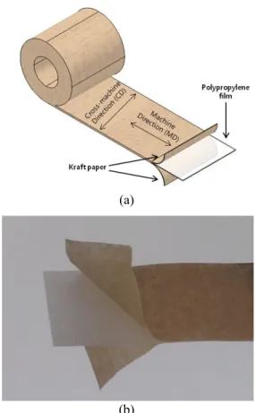
A polypropylene laminated paper (PPLP) with a thickness of 120 µm was supplied for the test. Fig. 1 is an illustration showing the orientation of PPLP which is made by polypropylene film sandwiched in between Kraft
Establishment of CTE Measurement Procedure for PPLP at 77 K for HTS Power Cables using Double Extensometers
Marlon J. Dedicatoria1, John Ryan C. Dizon1#, Hyung-Seop Shin1* and Ki-Duk Sim2
1 Department of Mechanical Design Engineering, Andong National University, Andong, Kyungbuk, 760-749 Korea
2 Korea Electrotechnology Research Institute, Changwon, 641-120 Korea
# Bataan Peninsula State University, Philippines Received 12 October 2012; accepted 13 November 2012
Marlon J. Dedicatoria, John Ryan C. Dizon, Hyung-Seop Shin and K. D. Sim
(a)
(b)
Fig. 1. (a) Illustration of PPLP sample used, including sample orientation; (b) PPLP material at disintegrated state.
papers on both sides. The sample length was 130 mm, while the gage length between the two copper grips was 80 mm. The machine direction (MD) as well as the cross-machine direction (CD) is indicated in Fig. 1(a). The disintegrated state is shown in Fig. 1(b).
2.2 Setup for CTE measurement
The thermal expansion of PPLP was measured at the temperature range of 300 K ~ 77 K using the configuration shown in Fig. 2. The upper end of the sample was gripped by the upper block, and a block (~ 45g dead weight) was attached to the lower end of the sample to ensuring vertical alignment. Aluminum foil was wrapped on the PPLP to avoid damage caused by the sharp edges of the double extensometer during gripping. The setup including the sample was slowly submerged into liquid nitrogen (77 K), which was used as the coolant.
The contraction of the sample was measured using the Nyilas type double extensometers with a gage length of 15 mm. The extensometers used in the study were made of Titanium alloy. The double extensometers were clipped to the sample.
The two single extensometers have been wired together, thus averaging the two displacement data electrically. The double extensometers were directly connected to the signal conditioner without using any Wheatstone bridge. And the voltage output from the signal conditioner was then recorded as a displacement caused by the shrinkage of sample during cooling to 77 K from RT.
(a) (b)
Fig. 2. (a) Setup for CTE measurement at 77 K, and (b) the enlarged view of the extensometer part.
2.3 Formulation for the determination of thermal contraction and CTE at cryogenic temperature
The double extensometers were calibrated at liquid nitrogen temperature around 77 K. From the slope of the voltage versus the displacement curve, the calibration factor was derived, and it was 1.77 V/mm.
The thermal contraction of a sample at a specified temperature T from room temperature (RT) can be computed based on the following equation:
εthermal = L∆L
@RT= L@RTL − L@T
@RT (1) where ∆L is the change in sample length which
corresponds to ∆V/CF@T.
L@RT is the initial length at room temperature which corresponds to the gauge length of the extensometer adopted
L@T is the length at a specified temperature T To compute the coefficient of thermal expansion, α, at a specified temperature T, the following equation was used:
α = εthermal∆T (2) where εthermal is the thermal strain measured over the temperature range and ∆T is the change in temperature.
Further, to derive the CTE, α, Eq. (1) was substituted to Eq. (2), such that :
α = ∆L�∆TL@RT (3) Using Eq. (3), we can then use the following relationship to compute the contraction, ∆L, using our setup:
∆L = α⋅∆T⋅L@RT = ∆V/CF@T (4) where CF @T is the calibration factor measured using the double extensometers at a specified temperature
∆V is the voltage change due to deformation during measurement
Deadweight Cu block (45.3g) Nyilas Double Extensometers
PPLPSample Aluminum foil Upper copper block
Gage length: 14.8mm 25
Establishment of CTE Measurement Procedure for PPLP at 77 K for HTS Power Cables using Double Extensometers Therefore, Eq. (2) then becomes as follows:
α =
CF@T∆V L@RT
�
∆T (5) And further,
α = CF ∆V
@T(L@RT)∆T (6) It should be noted that this formula works well as long as the linear CTE does not deviate much over the temperature range, ∆T. If it does, the equation must be integrated.
On the other hand, the thermal expansion calculation for continuous test (derived by a step of 1 K) was reported by Sugano et al. using the following equation [8]:
(7) where
L0 is the initial gauge length
V�(T) is the average voltage measured between T - 0.5 K and T + 0.5 K
y(T) is the temperature dependence of the calibration factor (CF)
3. RESULTSANDDISCUSSION 3.1 Validity check of measurement procedure adopted
To check the validity of the adopted thermal contraction measurement test procedure, the CTE and the thermal contraction of a 50 micron-thick brass tape was measured at 77 K and the result was compared to a reference data.
The test procedures were as follows:
1) Double extensometers calibration @ 77 K (or T):
calibration factor (CF) = 1.77 V/mm
2) Voltage output of the double extensometers has been measured to account for the thermal contraction of the
titanium alloy frame at a specified temperature, T, (i. e. @ 77 K in this study) V@ 77 K = -0.073 V
3) The voltage output corresponding to the change in length (∆L) of brass sample to 77 K from RT was measured using the double extensometers (as described in section 2.2); V@77 K = -0.164 V
4) Then, the thermal contraction at 77 K was calculated using Eq. (1).
From the mathematical formulation stated above, the thermal contraction strain measured was:
∆L
L (300 K − 77 K) = − 0.34 % Which yields an α of:
α = 15.4 x 10⁻⁶ K−1
These values showed a good agreement with the reference data [9]:
∆L
L(293 K−77 K)= − 0.353 % When α was computed, it showed:
α = 16.8 x 10⁻⁶ K−1
It was then decided that the measurement procedure using double extensometers could be also adopted for PPLP material at cryogenic temperature.
3.2 CTE measurement of PPLP
For measuring the CTE of the PPLP tape, the gauge length of the double extensometer adopted was 14.8 mm, shown in Fig. 2(b). Room temperature measured was ~ 27.2 °C (=300.2 K), while ∆T = 77 K – 300.2 K = 223.2 K.
From the formulation given above, the thermal contraction and the CTE of the PPLP tape at 77 K were measured both at MD and at CD orientations. Table 1 shows the measured data of the thermal contraction as well as the CTE of the PPLP tape. Three times per orientation were conducted, the average thermal contraction measured at MD orientation was -0.34% while the CTE calculated was ~ 15.3 x 10⁻⁶/K. For the CD orientation, the average thermal contraction measured was 0.87% while the CTE calculated was ~ 39.2 x 10⁻⁶/K.
The PPLP material showed different thermal properties depending on orientation; higher thermal contraction along the CD orientation as compared with the MD one. With this result, it can be found that the thermal contraction characteristic of PPLP was dominated by the polypropylene along CD orientation, while dominated by the Kraft paper along the MD one.
The mechanical and thermo-mechanical properties of composite materials depend on the respective properties of the matrix (polypropylene) and the reinforcing phases (fibers in Kraft paper), their relative volume fraction, length of the fiber and the orientation of the fibers relative to the applied stress direction [10]. Most of the fibers in the Kraft paper are oriented along the MD orientation, thus affecting mainly the thermo-mechanical and mechanical behavior of the PPLP along the direction [7]. However, the thermal contraction along the width (CD) is mostly perpendicular to the fiber direction; therefore the
TABLE I
CTE AND THERMAL CONTRACTION @77K FOR PPLP(C120N).
(10CTE -6 K-1)
Thermal contraction
∆L/L (%) Machine
direction (MD)
Test 1 16.0 -0.36 Test 2 14.6 -0.33 Test 3 15.2 -0.34
Mean 15.3 -0.34
Cross-Machine direction (CD)
Test 1 36.6 -0.82 Test 2 40.0 -0.89 Test 3 41.0 -0.91
Mean 39.2 -0.87
26
Marlon J. Dedicatoria, John Ryan C. Dizon, Hyung-Seop Shin and K. D. Sim
properties of the PPLP composite will be strongly dependent on the polypropylene matrix [10].
On the mechanical property aspect, the CTE compatibility of PPLP with coated conductor tapes must be considered and it should not be degraded under thermal contraction or cycling. Based on the above results, it can be found that the CTE of PPLP (~15.3 x 10⁻⁶/K along the MD direction) is comparable with HTS technical materials such as brass (17.5 x 10⁻⁶/K) or stainless steel (~15.0 x 10⁻⁶/K) [9]. It can be thought that the PPLP is a very suitable insulation for cable applications employing HTS tapes with brass or stainless steel reinforcements considering their CTEs. Consequently, it can be said that the determined CTE of the PPLP material makes an effective and reliable design of superconducting devices.
4. CONCLUSION
A CTE measurement procedure for PPLP material by using double extensometer method during cooling from 300 K to 77 K was established. Initially, the procedure was used to measure the CTE of a solid brass sample and compared the measured thermal contraction of the brass sample with the reference data. Based on the result, the measurement technique was applied to measure the CTE of PPLP material, which is flexible. As a result, the linear coefficient of thermal expansion of PPLP measured was ~ 15.3 x 10⁻⁶/K at 77 K. PPLP showed different thermal properties depending on orientation. This measurement procedure using double extensometers was effective for the determination of thermal contraction and CTE of PPLP material at cryogenic temperature.
ACKNOWLEDGMENT
This work was supported by a grant from National Research Foundation of Korea (NRF-2011-0015369) funded by the Korean Government (MEST) and partially by KERI.
REFERENCES
[1] S. H. Sohn, J. H. Lim, B. M. Yang, H. M. Jang, Y. H. Kim, H. S.
Yang, D. L. Kim, H. R. Kim, S. W. Yim, Y. J. Won and S. D.
Hwang, “Design and development of 500 m long HTS cable system in the KEPCO power grid, Korea”, Physica C, vol. 470, pp 1567–1571, 2010.
[2] S.H. Kim, J. H. Choi, W. J. Kim, K. L. Kim, H. G. Lee, Y. S. Kim, H.
M. Jang and S. K. Lee, “Electrical insulation characteristics of PPLP as a HTS DC Cable Dielectric and GFRP as insulating material for terminations”, IEEE Trans. Appl. Supercond., vol. 22, pp. 7700104, 2012.
[3] C. M. Rey and M. J. Gouge, “Electrical Insulation for Superconducting Applications”, Presentation at the U.S. DOE’s Superconductivity Program for Electric Systems 2005 Wire Development Workshop, St. Petersburg, Florida, 2005.
[4] N. Hayakawa, H. Kojima, M. Hanai, and H. Okubo, “Recent Progress in Electrical Insulation Techniques for HTS Power Apparatus”, Physics Procedia, vol. 36, 1305-1308, 2012.
[5] R. Hata, “Solid DC Submarine Cable Insulated with PPLP (Polypropylene Laminated Paper)”, SEI Technical Review, No. 62, 3-9, June 2006.
[6] Y.S. Choi and D.L. Kim, “Thermal property measurement of insulating material used in HTS power device”, Cryogenics, vol. 52, pp. 465-470, 2012.
[7] A. Gorospe and H.S. Shin, “Mechanical property evaluation of PPLP at cryogenic temperature”, Superconductivity and Cryogenics, vol. 14, No. 4, pp. 16-19, 2012.
[8] M. Sugano, K. Itoh, A. Nyilas, T. Kiyoshi, and S. Matsumoto, Measurement of thermal expansion by double extensometers between 290 K and 5 K, Physica C, vol. 426-431, pp. 1211-1215, 2005.
[9] J. Ekin, Experimental Techniques for Low-Temperature Measurements, Oxford University Press, 2006.
[10] R. Hertzberg, Deformation and Fracture Mechanics of Engineering Materials, John Wiley and Sons, Inc., 1996.
27