마이크로 및 나노 박막의 잔류응력을 측정하기위한 새로운 방법
강기주† · Evans, A.G. *
A New Method for Measuring Residual Stress in Micro and Nano Films
Ki-Ju Kang and Anthony G. Evans
Key Words : DIC (디지털 화상 관련법), FIB(집속 이온빔), Stress Relaxation(응력이완) Abstract
A new method to measure residual stress in micron and nano scale films is described. In the theory it is based on Linear Elastic Fracture Mechanics. And in the techniques it depends on the combined capability of the focused ion beam (FIB) imaging system and of high-resolution digital image correlation (DIC) software.
The method can be used for any film material (whether amorphous or crystalline) without thinning the substrate. In the method, a region of the film surface is highlighted and scanning electron images of that region taken before and after a long slot, depth a, is introduced using the FIB. The DIC software evaluates the displacement of the surface normal to the slot due to the stress relaxation by using features on the film surface.
To minimize the influence of signal noise and rigid body movement, not a few, but all of the measure displacements are used for determining the real residual stress. The accuracy of the method has been assessed by performing measurements on a nano film of diamond like carbon (DLC) on glass substrate and on micro film of aluminum oxide thermally grown on Fecrally substrate. It is shown that the new method determines the residual stress σ =-1.73 GPa for DLC and R σ =-5.45 GPa for the aluminum oxide, which agree quite R well with ones measured independently.
1. 서 론
물체의 표면에 코팅된 박막의 건전성 (integrity) 는 자체 내의 잔류응력 σ 에 크게 영향을 받는다. R 이밖에 박막의 균열이나 층분리 (delamination)에 영향을 미치는 인자로는 박막의 두께 , 탄성계 수 , 재료 또는 계면의 탄성파괴인성
h
Ef Γ가 있
다. 이 인자들 사이의 역학관계는 다음과 같은 무 차원량으로 표현될 수 있다.
h EfΓ σR2
= Σ
Σ
R
가 클수록 박막의 건전성을 증가한다. 여기서 σ 의 영향은 제곱으로 크게 작용함을 알 수 있다.
이것은 박막 내의 잔류응력의 중요성을 단적으로 보여준다. 기존의 잔류응력 측정법은 경우에 따라 유효하나 보편성이 결여되어 있다. X-선 회절법(1,2) 은 결정구조를 갖는 경우에만 유효하며 압전분광 법 (piezo-spectroscopy)(2~4)은 그 중에서도 투명한 고체에만 적용될 수 있다. 비결정 박막의 경우에 는, 현재까지, 층제거에 따른 곡률의 변화를 측정
하는 방법(5,6)이 유일하다. 그러나 이 방법은 측정
가능한 곡률의 변화가 발생할 만큼 충분히 박막하 부의 기판을 제거해야 하기 때문에, 재료에 따라 적용이 곤란한 경우도 많으며 시간과 비용면에서 도 불리하다.
전통적으로, 응력이완법 (stress relaxation method) 은 인기있는 잔류응력 측정방법의 하나이다. 시험 편을 절단하거나 일부를 제거하여 이완된 잔류응 력에 의한 탄성변형율을 측정하므로써 잔류응력을 구한다. 응력이완을 위하여 구멍을 뚫거나 (hole drilling), 절단하거나 (sectioning), 또는 위에서 언 급한 바와 같이, 표면으로부터 층을 제거하는
† 전남대 기계시스템 공학부 E-mail : [email protected]
TEL : (062)530-1668 FAX : (062)123-1234
* Materials Department, UCSB, USA
(layer removal) 방법이 사용되며, 변형율 측정에는 스트레인게이지가 가장 보편적으로 사용된다. 여 러가지 잔류응력측정법 중 응력이완법이 가장 정 밀한 결과를 주는 것으로 알려져 있다.(7)
물체의 일부에 균열, 엄밀히 말해서 가늘게 절 단) 하거나 얇은 홈 (slot)을 파는 것은 손쉬운 응 력 이완방법의 하나이다. 만일 변형율이나 변위를 균열 또는 홈의 깊이에 따라 연속적으로 측정한다 면 원래 존재하던 잔류응력의 ‘분포’를 구할 수 있다. 이 아이디어로부터 저자는 소위 ‘연속균열 법 (successive cracking method)’을 고안한 바 있다.
(8~10) 이와 같이, 균열을 내어 잔류응력을 측정하는
여러가지 방법들의 이론과 실용상의 문제는 Prime(11)에 의하여 상세히 조사된 바 있다. 이 방 법을 µm 또는 그 이하 두께의 박막의 잔류응력 측정에 적용하기 위해서는 균열 또는 홈을 만들고 변위나 변형율을 측정하기 위한 새로운 기술이 필 요하다.
본 연구에서는 FIB(Focused Ion Beam)을 이용하 여 박막의 표면에 홈을 만들고 이에 의한 응력이 완 변위를 디지털화상관련법 (DIC; Digital Image Correlation)으로 측정하여 잔류응력을 측정하는 방 법을 소개한다. 홈의 폭은 최소 5nm, 깊이는 50nm~10µm 까지 조절할 수 있으며, 변위의 해상 도는 최고 0.1 nm 에 달한다. 또한 기본적으로 박 막재료에 무관하게 적용할 수 있다. 기초이론과 함께 측정 사례로서 440nm 의 DLC (Diamond Like Carbon)과 이보다 10 배이상 두꺼운 알루미나 (thermally grown aluminum oxide) 박막의 잔류응력 측정과정 및 결과를 제시하였다.
2. 이 론
잔류응력장 내에 균열이 도입될 때 탄성해는 중첩의 원리(superposition principle)(12)에 의해서 구 해진다. 즉, 잔류응력의 이완에 의한 균열선단의 응력확대계수는 원래 존재하던 잔류응력과 크기가 같고 방향이 반대인 응력을 균열면에 가한 것에
Fig. 1 A schematic of a slot geometry and load states under residual stress and virtual forces.
의한 것과 같다. 한편, 균열 좌우에 x만큼 떨어진 지점 C, C´의 변위를 구하기 위해서 Castigliano 의 이론을 사용할 수 있다. 즉, Fig.1 과 같이 C, C´점 에 가상력 F 가 존재한다고 가정하면 그 점에서의 변위 ux는 다음식으로 표현된다.(13)
F da K K
ux =E′
∫
0a IR∂∂ IF1 ---- (1)
여기서 KIR, KIF는 각각 잔류응력 σ 과 가상력 R F 에 의한 응력확대계수(SIF)이다. a 는 균열길이, E´은 평면변형율 상태에 Young 계수이다. 균일한 잔류응력이 존재하는 박막의 경우 은 다음식 으로 표현된다.
KIR (14)
+
−
=
=
−
h a h
h a a f
h a f a K
s R IR
λ π
σ
1 1
) / (
) / ( 12
. 1
2 1 1
1
--- (2)
여기서 계수 s 와 λ 는 박막과 기판 사이의 탄성 부정합(elastic mismatch)을 나타내는 Dunders 매개 변수 α , β 의 함수이다. 박막과 기판의 재료가 동일하다면 가상력 F 에 의한 SIF 인 는 다음 식으로 표현된다.
KIF (13)
) 2 (
2θ πa f
KIF= F ,
(
1.12 0.18sec (tan ))
) 1 ( 2 1 sin cos )
( 2
2 θ
ν θ θ
θ h
f +
+ −
=
여기서 θ=tan−1
( )
x /a . 탄성부정합이 존재하는 경 우 그 영향은 식(2)에서와 같이 함수 로 표현될 수 있다고 가정하여 는 다음식으로 수 정하였다.) /
1(a h f KIF
Fig. 2 A schematic of a focused ion beam slot introduced into a film, defining the coordinates.
) / ( ) 2 (
1
2 f a h
a f KIF F θ
= π --- (3) 식 (2)와 (3)을 식 (1)에 대입하여 균열의 도입에 따른 잔류응력 이완에 의한 변위 는 다음식으 로 표현된다.
ux
da f E f
ux R a 2
0 2
' 1
12 . 1
4× ⋅
= σ
∫
--- (4)3. 측정 과정
Fig.2 는 박막에 만들어진 홈(slot)의 형상에 대한 개략도 이다. FIB 를 이용하여 주변의 손상을 최소 화 하면서 홈을 만들 수 있다. 홈을 내기 전에 전 자현미경(SEM)으로 표면사진을 찍는다. 이때 가능 한 한 표면의 거칠기에 의한 질감(feature)이 잘 보 이도록 촬영 조건을 맞춰줘야 한다. 이 흔적이 변 위를 측정할 때 기준점이 되기 때문에 표면에 얕 은 거칠기가 존재하는 것이 바람직하다. 그렇지않 은 경우에는 약한 이온빔으로 표면을 미리 주사 (ion scanning)하거나 MgO 와 같은 이물질 분말을 산포시키는 방법이 사용될 수 있다. 그 다음 FIB 로 가능한 한 가늘고 깊은 홈을 만든다. 기본이론 이 2 차원 탄성해이므로 홈의 길이 2L 은 깊이의 10 배 이상 되는 것이 바람직하다. 홈을 만든 후 다시 SEM 으로 표면사진을 찍는다. 이 두 SEM 사진을 비교하여 홈에 의한 응력이완 변위장 (displacement field)을 측정한다. 디지털 화상관련법 (DIC;Digital Image Correlation)(15,16)이 사용된다. 최 근의 상업용 DIC 소프트웨어는 화소의 1/100 크기 의 해상도를 가지고 있다. 변위장 측정 을 마친 후 역시 FIB 를 이용하여 홈을 수직으로 절단하여 그 단면을 드러내어 균열 깊이와 형상을 정확하게 측정한다.
Table 1 Material Properties Materials Young’s
Modulus
(GPa) Poisson Ratio DLC 103 0.2 Soda-lime
glass 69 0.2
α-phase
Al2O3 400 0.2
Fecralloy 120 0.3
측정된 변위로부터 응력 σ 을 측정하기 위해R 서 식 (4)를 사용한다. 그러나 한점이나 몇 개의 점에 대한 변위만으로 σ 을 측정하는 것은 곤란R 하다. 두 화상 사이의 변위, 정확히 말해서, 좌표 차이는 여러가지 잡음에 의한 흩어짐(scatter)과 함 께 구조적인 병진이동과 회전이동에 의한 것을 포 함하고 있기 때문이다. 따라서 다음과 같은 방법 을 사용하는 것이 더 타당하다. 박막 및 기판의 재료 물성을 알고 있다면, 가상적인 잔류응력
R=−1GPa
σ 이 존재하는 경우 각 측정점 에서
의 이론 변위는 식(4)에 의해서 계산될 수 있다.
이 변위를 라고 표시한다면, 동일한 점 에 서의 측정된 변위 와 사이에 다음과 같은 관계 가 성립한다.
a x/
x/
Ux a
ux
2
1U C
C ux = x+
변위장내의 여러점에 대한 - 데이터를 각각 수직-수평축으로 하여 나타내면, 절편 는 두 SEM 화상사이의 병진이동을, 는 실제 잔류응력
ux Ux
C1
C2
Fig. 3 SEM images of a region of the DLC film, (a) before the introduction of the FIB slot, (b) after.
Fig. 4 Scanning electron images of a FIB cross-section normal to the slot on the DLC film showing the film thickness as well as the slot depth and width.
σ 을 R 단위로 나타낸다. -U 데이터의 흩 어짐으로부터, 구해진
GPa ux x
σ 의 오차나 정밀도를 평R
가할 수 있다.
4. 측정 사례
4.1 DLC 박막
먼저, 2mm 두께의 소다유리(soda line glass) 기판 에 증착된 DLC(Diamond Like Carbon)의 잔류응력 을 측정하였다. DLC 박막과 유리 기판사이의 계면 이 비교적 낮은 인성을 가지고 있고 압축잔류응력 이 존재하기 때문에 계면분리 및 좌굴에 의한 전
Fig. 5 Displacement distribution measured from SEM images for the slot on the DLC film by using the DIC software; (a) left side, (b) right side.
화선 형태(telephone cord morphology)의 파손이 자 주 발생한다.(14,17,18) DLC 박막의 두께는 440nm 이 고 탄성 재료물성은 Table 1 에 나열되어 있다.
Fig.3(a)와 3(b)는 각각 FIB 홈을 만들기 전·후의 SEM 화상을 보여주고 있다. 여기서 낮은 출력의 이온빔으로 두개의 큰 사각형을 먼저 작도하고, 그 사이에 FIB 홈을 만든 것(출력 10pA)을 볼 수 있다. 이것은 홈의 위치를 쉽게 찾기 위한 것이다.
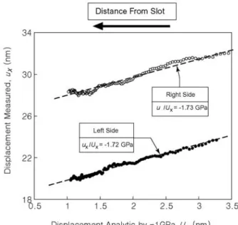
Fig. 6 Comparisons of the measured displacements from Fig.5 (ordinate), with the displacement obtained by using the analytic solution Eq.(4) (abscissa)) for an assumed residual stress of - 1GPa in the DLC film.
Fig. 7 SEM images of a region of the DLC film, (a) before the introduction of the FIB slot, (b) after.
Fig.4 는 홈의 단면을 보여주고 있다. FIB 절단과 정에 발생할 수 있는 표면의 손상을 막기 위하여 백금(Pt) 코팅을 추가한 것을 볼 수 있다. 홈의 깊 이는 a=280nm, 폭은 W 220nm, 길이는 2L=10≈ µm 이다.
Fig.3(a)와 3(b)의 두 화상으로부터 상대적 변위 를 구하기 위해 DIC 소프트웨어인 Correlated Solution 사의 VIC-2D 를 사용하였다. 최고의 정밀 도를 보장하기 위해서 65 65 픽셀의 서브셋 (subset) 크기를 사용하였으며 홈 모서리 근처의 데이터는 이온빔에 의한 표면손상과 이상적 균열 에 의한 것과의 편차
ux
×
(19) 때문에 제외하였다.
Fig.5(a)와 5(b)는 각각 홈 좌·우에서 측정된 변위 를 나타내고 있다. 3 가지의 y 좌표에 대하여 측정 된 분포가 거의 평행한 것으로 보아 화상 사이에 회전이동이 없었음을 알 수 있다. Fig.6 은 y=0 에서 측정된 변위 을 수직축으로, -1 의
가상잔류응력이 존재할 때 이론적인 변위 를 수평축으로 나타낸 것이다. - 의 기울기로부 터 구해진 잔류응력은 홈 좌·우면에서 각각 –1.72 와 –1.73 이다. 이것은 층 제거에 따른 곡률측 정법
x ux−
ux GPa
Ux
ux Ux
m GPa
(5)과 좌굴단면의 형상으로부터 예측된(17) –1.6 과 잘 일치한다.
GPa
µ
µm α
4.2 알루미나 박막
전기발열체(heating element) 소재인 Fecralloy (Fe72.8/Cr22/Al2/Y0.1/Zr0.1) 100 두께 박막을 전기로에서 1200℃로 3 일간 산화시켜 표면에 5.3 두께의 알루미나(Al2O3)가 생성되도록 하였 다. 이 알루미나는 루비나 사파이와 같은 치밀한 조직의 -상 결정으로 가스터어빈 엔진 내 열차 단막(Thermal Barrier Coating)의 건전성에 중요한 역할을 하는 것으로 알려져 있다.(20,21) 탄성 재료
Fig. 8 Displacement distribution measured from SEM images for the slot on the alumina film by using the DIC software; (a) left side, (b) right side.
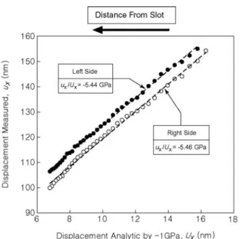
Fig. 9 Comparisons of the measured displacements from Fig.8 (ordinate), with the displacement obtained by using the analytic solution Eq.(4) (abscissa)) for an assumed residual stress of - 1GPa in the aluminum oxide film.
물성은 Table 1 에 나열되어 있다.
DLC 에서 보다 강력한 300pA 의 FIB 으로 홈을 가공하였다. 홈의 깊이는 a=3.4 µm , 폭은 W=
1.6µ , 길이는 2L=38m µ 이다. Fig.7(a)와 7(b)는 각m 각 홈 가공 전·후의 표면 SEM 화상을 보여주고 있다. Fig.8(a)와 8(b)는 각각 홈 좌·우 면에서 VIC- 2D 로 측정된 변위 분포 를 보여주고 있다.
Fig.7 에서 볼 수 있듯이 거친 표면이 좋은 질감 (feature)을 제공하므로 측정된 변위로 흩어짐 없는 매끈한 양상을 나타내고 있다. 다른 y-좌표에서 가 서로 평행하여 두 화상사이에 회전이동 이 없었다는 것을 알 수 있다. Fig.9 은 각각의 측 정점에 대해 측정된 를 수직축에 -1 의 가 상잔류응력에 의한 이론 변위 를 수평축에 도 시한 것이다. 기울기로부터 구해진 잔류응력은 좌·
우면에서 각각 5.44 와 5.46 로 1% 이내로 일치한다. 이것은 Fig.6 의 DLC 에 대한 것보다 정 밀한 것으로 양호항 표면질감에 힘입은 것이다.
유사한 결과가 비슷한 재료에 대한 압전분광확법 (piezo-spectroscopy)에 의하여 측정된 바 있다.
x ux−
U
−x ux
ux
GPa
GPa
x
GPa
(22)
5. 결 론
마이크로 혹은 나노 두께 박막의 잔류응력 측 정을 위한 새로운 방법이 소개되었다. 이것은 기 술적으로는 FIB 와 디지털 화상관련법을 응용하며,
이론은 선형탄성파괴역학에 기반을 두어 명백하고 단순하다. 이 방법은 결정, 비결정에 관계없이 박 막재료에 무관하다. 박막 표면에 FIB 로 홈을 만 들기 전·후의 SEM 화상을 비교하여 디지털 화상 관련법으로 응력이완에 의한 변위를 측정한다. 측 정된 변위를 -1 의 가상잔류응력에 의한 변위 와 비교하여 잔류응력은 결정된다. DLC 와 알루미 나 박막을 대상으로 본 방법을 적용한 결과, 각각
GPa
σ =-1.73R 과 -5.45 의 결과를 얻었으며 이 는 기존의 다른 연구결과와 잘 일치하였다.
GPa GPa
참고문헌
(1) Noyan, I.C. and Cohen, J.B., 1987, Residual Stress Measurement by Diffraction and Interpretation.
Springer, Berlin Heidelberg New York, pp.166-181.
(2) Vosberg, V.R., Clemens, D., Berger, M.G., Fisher, W., and Nickel, H., 1997, “Stress in alumina scales on high-temperature alloys measured by X-ray and optical methods” Fresenius J Anal Chem, Vol. 358 pp.127-130.
(3) Lipkin, D.M. and Clarke, D.R., 1996, “Measurement of the stress in oxide scales formed by oxidation of aluminum-containing alloys”, Oxidation of Metals, Vol.45, pp.267-280.
(4) Ma, Q. and Clarke, D.R., 1993, “Optical Fluorescence from chromium ions in sapphire: A probe of the image stress”, Acta Metallurgica Materialia, Vol.41, pp.1811-1816.
(5) Cho, S.J., Lee, K.R., Eun, K.Y., Hahn, J.H., and Ko, D.H., 1999, “Determination of elastic modulus and Poisson’s ratio of diamond-like carbon films” Thin Solid Films, Vol.341, pp.207-210.
(6) Witvrouw, A. and Spaepen, F., 1993, “Determination of the plane stress elastic constants of thin films from substrate curvature measurements: Applications to amorphous metals”, Journal of Applied Physics, Vol.73, pp.7344-7350.
(7) Masubuchi, K., 1980, Analysis of Welded Structures, Pergamon Press.
(8) Kang, K.J., Song, J.H., and Earmme, Y.Y., 1989, "A method for the measurement of residual stresses using a fracture mechanics approach", J. of Strain Analysis for Engineering Design, Vol.24, pp.23-30.
(9) Kang, K.J. and Choi, S.R., 1993, "Residual stress measurement for circular disk using fracture mechanics approach", Transactions of Korean Society of Mechanical Engineers, Vol.17, pp.1218-1226 (in Korean).
(10) Kang, K.J. and Seol, S.Y., 1996, “Measurement of residual stresses in a circular ring using the successive cracking method”, ASME Trans. J. of Engineering Materials and Technology, Vol.118 pp. 217-223.
(11) Prime, M.B., 1999, “Residual stress measurement by successive extension of a slot: The crack compliance method”, Appl Mech Rev Vol.52, pp.75-96.
(12) Aamodt, B. and Bergan, P.G., 1976, "On the
Principle of Superposition for Stress Intensity Factors", Eng. Fracture Mechanics, Vol. 8, pp. 437-440.
(13) Tada, H., Paris, P., and Irwin, G., 1973, The Stress Analysis of Cracks Handbook, Del Research Corporation.
(14) Hutchinson, J.W., Suo, Z., 1992, “Mixed mode cracking in layered materials”, Advances in Applied Mechanics, Vol.29, pp.63-191.
(15) Sutton, M.A., Cheng, M., Peters, W.H., Chaou, Y.J., and McNeill, S.R., 1986, “Application of an optimized digital correlation method to planar deformation analysis”, Image and Vision Computing, Vol.4, pp.143- 151.
(16) Schreier, H.W., Braasch, J.R., and Sutton, M.A., 2000, “Systematic errors in digital image correlation caused by gray-value interpolation”, Opt. Eng. Vol.39, pp.2915-2921.
(17) Moon, M.W., Jensen, H.M., Hutchinson, J.W., Oh, K.H., and Evans, A.G., 2002, “The characterization of telephone cord buckling of compressed thin films on substrates”, J. Mech. Phys. Solids, Vol.50, pp.2355- 2377.
(18) Moon, M.W., Chung, J.W., Lee, K.R., Oh, K.H., Wang, R., and Evans, A.G., 2002, “An experimental study of the influence of imperfections on the buc kling of compressed thin films” Acta Materialia, Vol.50, pp.1219-1227.
(19) Kang, K.J., Darzens, S., Choi, G.S., and Evans, A.G., 2003, “Effect of geometry & materials on residual stress measurement in thin films by using the focused ion beam”, in preparation.
(20) Evans, A.G., Mumm, D.R., Hutchinson, J.W., Meier, G.H. and Pettit, F.S., 2001, “Mechanisms Controlling Durability of Thermal Barrier Coatings”, Prog. Mater. Sci., Vol.46, pp.505-553.
(21) Karlsson, A.M., Hutchinson, J.W. and Evans, A.G., 2002, “A fundamental model of cyclic instabilities in thermal barrier systems”, J. Mech. Phys. Solids, Vol.50, pp.1565-1589.
(22) Tolpygo, V.K., Dryden, J.R., and Clarke, D.R., 1998, “Determination of the growth stress and strain in α-Al2O3 scales during the oxidation of Fe-22Cr- 4.8Al-0.3Y alloy”, Acta Mater., Vol.46, pp.927-937.