A Comparative Study on Power Generation Characteristics of Permanent Magnet Synchronous Generators for Green Ship
Shinji Kato†⋅Gyeong-Rae Cho1⋅Masakazu Michihira2
(Received November 18, 2011; Revised December 12, 2011; Accepted April 18, 2012)
Abstract:For reduction of the amount of CO2 emitted from ships, power generation characteristics of two power generation systems consisting of a high-efficiency permanent magnet synchronous generator and diode bridge rictifiers are discussed in this paper. One of the discussed systems has three-phase stator windings, and the other has two sets of three-phase (six-phase) stator windings to reduce pulsation in the electromagnetic torque and DC current. Experimental results reveal that the power generation efficiency of the system having six-phase stator windings is higher than that of the system having three-phase stator windings for a light load. The maximum power generation efficiency of the system having six-phase stator windings is almost the same as that of the system having three-phase stator windings. For the electromagnetic torque of the system having six-phase stator windings, the width of pulsation is about one-fifth compared to the system having three-phase stator windings.
Key words:Six-phase permanent magnet synchronous generator, Diode bridge rectifier, Power generation characteristics
†Corresponding Author (Kobe City College of Technology of Japan, E-mail:[email protected], Tel:+81-78-795-3238) 1 G.R. Cho, Div. of Mech. and Energy Systems Eng., Korea Maritime Univ.
2 Kobe City College of Technology of Japan
This paper is extended and updated from the short version that apeared in the Proceedings of the International symposium on Marine Engineering and Technology (ISMT 2011), held at BEXCO, Busan, Korea on October 25-28, 2011.
1. Introduction
Almost 90 % of the world trade is carried by ships, and for the vast majority of this trade there is little or no alternative to transport by ships.
Compared with truck, rail, and airplane, ship is the most eco-friendly transportation mean in view of emitted CO2. However, it is estimated that 2.7 % of the global CO2 emissions come from international shipping. For reduction of the amount of CO2 emitted to atmosphere and protection of global environment, a green ship is attractive for the future ship in recent years.
Ships consist of many mechanical and electrical parts, and one of the important electrical parts is a
generator because all electrical power used in ship is produced by it. The improvement of generator efficiency contributes to reduction of the amount of emitted CO2 and consumed fossil fuel. In the most ships, conventional synchronous generators with field windings are driven by a prime mover such as diesel engines. Since the conventional synchronous generators have brushes and slip rings, it make generation system reliability low. In these days, permanent magnet synchronous generators (PMSGs) have been used in large-scale power generation systems owing to the development of perm-anent magnet materials. For example, 7 MW offshore wind power generation system is now been
studied and designed [1]. Compared with conventional synchronous generators, PMSGs provide high power generation efficiency because losses in the rotor are small. This means that PMSGs can reduce the amount of emitted CO2.
There are no brushes and slip rings in PMSGs, so that the higher reliability can be obtained. However, the power converters are very expensive because their power rating is the same as the generated power.
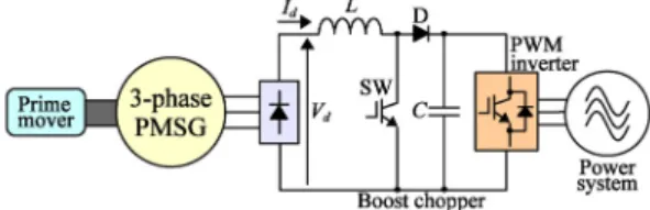
In order to use an inexpensive power converter instead of an expensive pulse-width modulation (PWM) rectifier, the conventional power generation system using a three-phase PMSG and a threephase diode bridge rectifier shown in Figure 1 have been proposed [2]. From the results of computer simulation, we found that the fifth and seventh harmonic stator currents produced large pulsation of the DC current and electromagnetic torque [3, 4].
Thus, we proposed a novel power generation system consisting of a six-phase PMSG and two threephase diode bridge rectifiers [5]. Through computer simulation, we confirmed that pulsation of the electromagnetic torque produced by harmonic stator currents was very small [3, 4].
However, we have not yet presented or discussed the generation characteristics of the two power generation systems. In this paper, we present and discuss the generation characteristics through simulation and experiments using 2.2 (kW) PMSGs.
2. Two Generator Systems
2.1 Conventional Power Generation System
The conventional power generation system shown in Figure 1 consists of a three-phase PMSG, three-phase diode bridge rectifier, boost chopper, and three-phase PWM inverter [2].
The three-phase diode bridge rectifier converts generated AC power, whose frequency depends on the rotational speed of the generator, into DC
Figure 1: Conventional power generation system.
power with no control by semiconductor devices.
However, the DC current () and electromagnetic torque pulsate because the three-phase diode bridge rectifier produces harmonic stator currents, such as fifth and seventh harmonics, whose components are 6±1 (where is an integer).
The boost chopper consisting of an inductor (), semiconductor device (SW), and diode (D) controls generation power and boosts the output voltage () to the input voltage of the three-phase PWM inverter by adjusting a duty ratio. The three-phase PWM inverter converts DC power into three-phase AC power, whose frequency conforms to that of power system, and sends it to power systems.
2.2 Proposed Power Generation System
Pulsation of the DC current and electromagnetic torque is produced by harmonic stator currents in the conventional power generation system. This demands large smooth inductance and implies that torsional torque may arise in mechanical coupling.
We proposed the novel power generation system shown in Figure 2 to solve those problems [5].
1) Configuration
The configuration of the proposed power gen- eration system is the same as that of the conven-
Figure 2: Proposed generator system.
tional power generation system except for the stator windings and the number of three-phase diode bridge rectifiers. As shown in Figure 3, there are two sets of three-phase stator windings spatially shifted by 30 electrical degrees. The neutral points of stators1 ( ) and stator2 ( ) are isolated.
The two diode bridge rectifiers (DB1, DB2) are connected in series rather than in parallel because the parallel connection requires interphase reactors to produce balanced currents. It is easy to achieve a higher DC voltage.
2) Method for reducing pulsation of the electromagnetic torque
The two three-phase diode bridge rectifiers are connected to two sets of three-phase stator windings so that stator currents become a rectangular waveform if the overlap of currents is ignored. Figure 4 shows stator current waveforms with the DC current () under an ideal condition;
i.e., there is no overlap.
Applying the Fourier series expansion to the a-phase current waveform of stator1 () gives
sint
n ⋯
∞
±
sin ±
⋯
∞
±
sin ±
(1) a1b1
c1
a2
b2
c2
=30(deg.)
t x1
x2
y1
y2
z1
z2
Figure 3: Cross-section diagram of the six-phase PMSG.
ia1 ia2
ib2
Ia ia2b2
0 30 60 90 120 150 180 210 240 270 300300 330 360 t (deg.) Id
Id
Id
3 3Id 1 3
3 Id 1 2 3 3 Id 1
3Id
2 3Id
Figure 4: Stator current waveforms of the proposed generator system.
Similarly, the line current waveform of stator2 (ia2b2) can be expressed as
sint
n ⋯
∞
±
sin ±
⋯
∞
±
sin ±
(2)By adding (1) and (2), the resultant current of a-phase (Ia) can be expressed as
sint
⋯
∞
±
sin ±
(3)For the conventional power generation system, the MMF contributing to a rotating magnetic field is produced by the current expressed as (1). On the other hand, the current expressed as (3) produces the MMF of the proposed power generation system.
From comparison of (1) with (3), it is found that the 11th and 13th harmonic MMF components of the proposed power generation system are dominant, while the 5th and 7th components are dominant in the conventional power generation system. Consequently, the proposed power generation system can reduce pulsation of the electromagnetic toque.
3) Method for reducing pulsation of the DC current
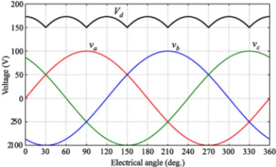
Pulsation of the DC current occurs during the rectification of the three-phase diode bridge rectifiers. It is assumed that the waveform of induced electromotive force (EMF) is sinusoidal. As shown in Figure 5 (a), the obtained waveform of DC voltage for the conventional power generation system contains pulsation. Owing to six commutations of diodes during one cycle, the frequency of pulsation is 6 (where is the frequency of the induced EMF). If a resistor is connected to the output terminal of the diode bridge rectifier, the waveform of DC current has the same shape as the DC voltage.
For the proposed power generation system, two three-phase induced EMFs are produced. The phase difference between the EMFs of stators1 ( ) and stator2 ( ) is 30 elec-
Figure 5: Voltage waveforms of the induced EMF and DC voltage.
trical degrees. The two induced EMFs produce two output DC voltages ( ) with pulsation frequency of 6; thus, the pulsation frequency of the resultant DC voltage () is 12. The amplitude of the resultant DC voltage is twice that of the conventional power generation system, and the width of pulsation is very small.
3. Simulation and experiments
Simulation and experiments were performed for two 2.2 (kW) PMSGs to obtain characteristics of the two power generation systems.
3.1 Simulation method
The conventional and proposed power generation systems have many diodes so as to convert the generated AC power into the DC power, so that circuit topology is continually changed by the conducting states of diodes. In the proposed power generation system, for example, the number of conducting states is 36 without commutation overlap of stator currents [6]. Therefore, it is significantly difficult to simulate both systems by using the equivalent circuit on the reference frame in consideration of commutation overlap. Hence we used the original simulation tool developed by one of the present authors [7, 8]. Since the original simulation tool uses the voltage and torque equations on the abc reference frame, there is no need not only to derive those equations on the reference frame but also to consider commutation overlap and the conducting states of diodes.
3.2 Experimental setup
The power converter consisting of a boost chopper and three-phase PWM inverter shown in Figures. 1 and 2 is connected to three-phase diode bridge rectifiers, but a variable load resistor () is connected to the output terminal depicted in Figure 6 when simulation and experiments were carried out.
Without controlling the DC current () with the boost chopper, an obvious difference in pulsation of the DC current can be obtained.
Figure 6: Experimental setups.
Figure 7: Photograph of two generators and a DC motor.
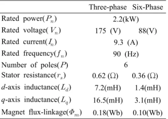
Table 1: Parameters of PMSGs
Three-phase Six-Phase Rated power() 2.2(kW) Rated voltage() 175 (V) 88(V) Rated current() 9.3 (A) Rated frequency() 90 (Hz)
Number of poles() 6
Stator resistance() 0.62 (Ω) 0.36 (Ω) d-axis inductance() 7.2(mH) 1.4(mH) q-axis inductance() 16.5(mH) 3.1(mH) Magnet flux-linkage() 0.18(Wb) 0.10(Wb)
Figure 7 is a photograph of two PMSGs and a DC motor used in the experiment, and Table 1 gives parameters of the three-phase and six-phase PMSGs. Each generator is driven by the DC motor connected to two PMSGs through a mechanical coupling. The three-phase PMSG is a commercially used permanent magnet synchronous motor manufactured by Fuji Electric. In the six-phase PMSG, the rotor is of identical type to that of the
three-phase PMSG. The two three-phase stator windings are rewound with half the number of turns per phase in the three-phase PMSG.
3.3 Simulation and experimental results
Since the rated operating speed of two generators is 1800(=120 ․ = 120 ․ 90/6) (min-1), three operating speeds of 1700 (min-1), 1800 (min-1) and 1900 (min-1) was selected. The variable load resistance was optimally adjusted in order to change the generated power by about 100 (W).
1) Stator and DC currents
Many results of simulation and experiment was obtained; however, only a few of them are depicted in this paper because of space limitations.
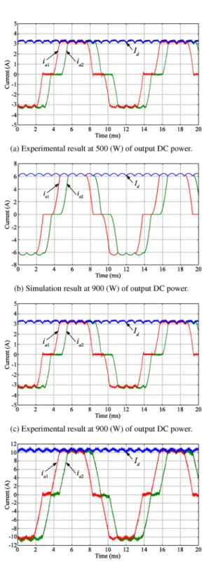
Figures 8 and 9 show simulation and experimental results of the conventional and proposed power generation systems, respectively.
The output DC power of 500 (W) is minimal in all measured data, and 1200 (W) is maximal in them.
The output DC power of 900 (W) is the maximal point of power generation efficiency. The current range in Figures. 8 and 9 differs in three output DC power because we want to show the obvious difference in the shape, ripple and overlap of current waveforms.
The simulation results for two power generation systems at 900 (W) of output DC power agree well with experimental results. For all output DC power, the stator currents of the conventional power generation system are trapezoidal waveforms with pulsation because of the large inductance of the stator windings and the three-phase diode bridge rectifier. The large inductance results in overlap of the stator currents.
Figure 8 shows that as stator currents increase, the term of overlap lengthens and that of the zero current shortens. As shown in Figure 5 (a), the DC voltage (or current) waveform has a pulsation frequency of 6f.
Since the operating speed is 1800 (min-1) and the number of poles is 6, the frequency of induced EMF is 90 (Hz). Thus, the pulsation frequency of DC cur-
Figure 8: Stator and DC currents of the conventional power generation system at an operating speed of 1800 (min-1).
Figure 9: Stator and DC currents of the proposed power generation system at an operating speed of 1800 (min-1).
rent is 540 (Hz). The width of pulsation is around 1.5 (A) at 900 (W) of output DC power.
In the proposed power generation system, the waveform of stator currents is similar to that in the conventional power generation system. Since the inductance of stator windings is about one-fifth of that for the three-phase PMSG, the stator currents have a gradient higher than that for the conventional power generation system shown in Figure 9. In addition, the term of the zero stator current is long. As a result, the term of overlap of stator currents is shorter than that of the conventional power generation system. Figure 5 (b) shows that the DC voltage (or current) has a pulsation frequency of 12. It is confirmed from Figure 9 that the DC current has pulsation frequency of 1080 (Hz) at an operating speed of 1800 (min-1). The width of pulsation is around 0.35 (A) at 900 (W) of output DC power. The width is about one-fifth of that for the conventional power generation system.
2) Electromagnetic torque
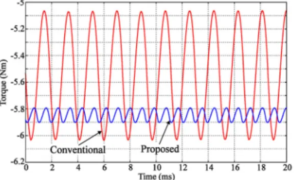
Electromagnetic torque waveforms obtained from simulation results at 900 (W) of output DC power and an operating speed of 1800 (min-1) are shown in Figure 10. For the conventional power generation system, the electromagnetic torque is produced by the stator current of a-phase (ia1) ex-
Figure 10: Electromagnetic torque waveforms of simulation results at 900 (W) of output DC power and an operating speed of 1800 (min-1).
pressed by (1). The sixth harmonic component of the stator current is dominant with respect to the fundamental component, and thus, the torque has a pulsation frequency of 6; i.e., 540 (Hz). The width of pulsation is around 0.97 (Nm).
On the other hand, the stator current producing electromagnetic torque in the proposed power generation system is expressed by (3); thus, the 12th harmonic component is dominant and the pulsation frequency is twice that of the conventional power generation system. Therefore, the width of pulsation is considerably less than that of the conventional power generation system. In fact, the width of pulsation is around 0.21 (Nm).
The stress on the mechanical coupling due to pulsation of the electromagnetic torque is very low.
3.4 Power Generation Characteristics
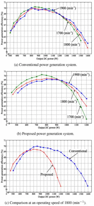
Figure 11 shows the power generation efficiency of the two power generation systems at operating speeds of 1700, 1800, and 1900 (min-1). The efficiency is calculated by dividing the output DC power () by the input power of the DC motor. Thus, the efficiency includes copper losses, iron losses, mechanical losses, and conduction losses of semiconductor devices. Figures 11 (a) and (b) show that the efficiency tends to decrease as the output DC power increases. There are points of highest efficiency between 800 and 900 (W) of output DC power for two power generation systems.
It can be observed from these figures that the two power generation systems are suitable for light loads while running at low speeds and for heavy loads while running at high speeds. Figure 11 (c) shows the power generation efficiency of two power generation systems at an operating speed of 1800 (min-1). For a light load, the efficiency of the proposed power generation system is higher than that of the conventional power generation system by about 1 %. When the output DC power exceeds 750 (W), the efficiency of the conventional power generation system is much higher
Figure 11: Power generation efficiency.
than that of the proposed power generation system.
One of the reasons of difference in efficiency is the armature reaction of stator currents. Another reason is that the distribution of stator winding of the six-phase PMSG could not be optimized due to limitations of the number and space of slots.
4. Conclusion
For reduction of the amount of CO2 emitted from ship, power generation characteristics of two power generation systems, which can produce high power generation efficiency, are presented and discussed in this paper; simulation and experiments are performed with 2.2 (kW) PMSGs. The maximal power generation efficiencies of the two systems are almost the same. In comparison with the conventional power generation system, the power generation efficiency of the proposed power generation system is slightly high for a light load; i.e., there is a little containers on ship, but it is low for a heavy load. The main factor of difference in efficiency is the unoptimized distribution of stator winding of the six-phase PMSG.
Pulsation of the electromagnetic torque and DC current is very small in the proposed power generation system compared to that in the conventional power generation system. The proposed power generation system reduces the cost of smooth inductor in the boost chopper and generates minimal stress to the mechanical coupling.
In order to improve the power generation efficiency of the proposed generation system, it needs the optimal design of the six-phase PMSG. We anticipate that the power generation efficiency of the proposed power generation system is almost the same that of the conventional power generation system when the experiments is carried out with the optimal designed six-phase PMSG.
The proposed power generation system is useful in a green ship because this system reduces the amount of consumed fuel, and gives high reliability, low cost, and low pulsation of the electromagnetic torque as compared with conventional used generator systems in ships.
Acknowledgment
This work was partly supported by the National Research Foundation grant funded by the MEST of (No. 2008-0060153).
References
[1] Vestas Homepage (http://www.vestas.com),
“V164-7.0 MW”, 2011.
[2] K. Amei, Y. Takayasu, T. Ohji and M. Sakui,
“A maximum power control of wind generator system using a permanent magnet synchronous generator and a boost chopper circuit,” Power Conversion Conference-Osaka (PCC-osaka), pp.
1447–1452, April 2002.
[3] S. Kato, Y. Inui and M. Michihira, “A comparative study of steady-state characteristics of permanent magnet synchronous generator systems,” Proceedings of the 12th European Conference on Power Electronics and Applications (EPE2007), September 2007.
[4] S. Kato and M. Michihira, “Modeling, simulation, and experimental verification of a permanent magnet synchronous machine with dual three-phase stator winding,” Proceedings of the 9th International Conference on Modeling and Simulation of Electric Machines (ELECTRIMACS2008), June 2008.
[5] S. Kato, Y. Inui, M. Michihira and A.
Tsuyoshi, “A low-cost wind generator system with a permanent magnet synchronous generator and diode rectifier,” Proceedings of the International Conference on Renewable Energy and Power Quality (ICREPQ'07), March 2007.
[6] W. S. Zakaria, A. A. Shaltout, and S. R.
Alwash, “A novel double-circuit-rotor balanced induction motor For improved slip-energy recovery drive performance-part II-,” IEEE Transactions on Energy Conversion, vol. 11, no.
3, pp. 563–569, Sep 1996.
[7] S. Kato, N. Hoshi, and K. Oguchi, “Analysis of power electronics systems including cascaded induction machines with modified nodal analysis”, Proceedings of the Power Conversion Conference-Osaka, pp. 282-287, Apr 2002.
[8] S. Kato, M. Michihira, and A. Tsuyoshi,
“Modeling and simulation of a permanent magnet synchronous machine with six-phase stator winding for renewable energy applications”, Proceedings of the 2006 International Conference on Electrical Machines and Systems, Nov 2006.
Author Profile
Shinji Kato
He received his B.E. and M.E. from Ibaraki Univ. in 2000 and 2002, respectively. He then received his Ph.D.
degree from Ibaraki Univ. in 2005. He is currently an associate professor in the Department of Electrical Engineering, Kobe City College of Technology. Main interests are in the areas of drive or generation systems with multi-phase machines.
Gyeong-Rae Cho
He received his B.S. degree in Refrigeration and Air conditioning and Energy Systems from Korea Maritime Univ. in 1999. He then received the Ph.D. degree in Mechanical Eng. in Saitama Univ. in 2004.
Masakazu Michihira
He received the B.E. and M.E. degree from Kobe University in 1993 and 1995.
He received the Ph.D. degree from Osaka University in 1998. He joined the Department of Electrical Engineering, Kobe City College of the Technology as a research associate in 1998 and since 2011 as professor.
His research interests are application development of power electronics circuits and systems.