파형 강판 파이프 아치 암거의 최소 토피 두께의 제안
Yeau, Kyong Yun
*여경윤
ABSTRACT
본 논문의 주된 목적은 농업용 이동로 또는 농업용수의 공급을 위하여 사용되는 파형 강판 파이프아치 암거가 고속도로 및 지방국도를 통과할 때 설계 및 시공 시 요구되는 최소 토피 두께를 제안하는데 있다. 1998년 이후 농업용 목적으로 사용되는 파 형 강판 암거는 서해안 고속도로의 건설과 더불어 그 수요량이 증가하였으며, 이에 따른 설계 및 시공의 빈도수 또한 지속적으 로 증가하고 있는 추세이다. 그러나 이를 뒷받침 할 수 있는 국내 규정은 아직 미약한 실정이다. 따라서 본 연구에서는 파형 강 판 암거의 설계 및 시공 시 고려해야 할 가장 중요한 인자 중 하나인 최소 토피에 대한 연구를 수행하고 그 두께를 제안하였다. 현재 국내 및 미국에서 사용되고 있는 최소 토피 두께는 암거의 스판 길이 또는 스판 길이와 암거의 높이 비율의 관계로부터 정 해지는 것으로 구조적인 특성치를 포함하고 있지 않다. 제안된 최소 토피 두께는 암거의 형상적 특성, 설계 하중, 강판의 구조적 특성과 손상 등을 반영하여 파형 강판 암거의 안전성을 극대화 하였다. 제안된 토피 두께는 미국과 국내 도로공사에서 규정하고 있는 토피 두께와 비교 분석하였으며, 그 결과 국내 규정이 더욱 안전성을 고려하고 있음을 알 수 있었다.
Keywords: Corrugated metal culverts; minimum cover; pipe-arch; structural properties
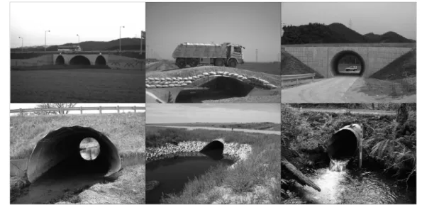
The first corrugated metal culvert passed through the Joongang expressway was constructed in 1990s as an agricultural underpass, which uses a passage for agricultural equipments. After the passage, many flexible corrugated metal culverts with spans larger than 3 m have been used as agricultural drainage structures and underpasses for many years in Korea and the usage of these structures is gradually increased due to construction of expressways and local ways passed over wide plains and agricultural farmlands. According to the Korea Expressway Corporation (KEC) inventory, about 10% (about 100 culverts) of existing culverts crossing over expressways are used as agricultural underpasses and drainage structures. Most culverts used for agricultural drainages and underpasses are pipes, pipe-
* 한국도로공사 도로교통연구원
Tel.: +82-31-371-3310 Fax: +82-31-371-3379 E-mail: [email protected] 2010년 4월 21일 투고 2010년 5월 31일 심사완료 2010년 6월 1일 게재확정
arches, and arches as shown in Fig. 1. The design of culverts is based on the composite interaction between the soil and the culvert plates. The design criteria and code requirements have been established by KEC (2002).
One of the failure criteria is the soil failure due to the induced shear and dilation in the soil. Although the provisions for the minimum cover design are determined to avoid the problems associated with soil failure, these requirements are originally empirical (Hafaz and Abdel- Sayed, 1983). Many researchers (Kim et al., 2009, Abdel- Sayed and Salib, 2002; Hafez, 1981) have tried to find the minimum cover depth based on the finite element programs like CANDE and ABAQUS. However, the existing literature, to our knowledge, contains little information on the minimum cover depth based on the analytical approaches.
Culverts have different soil cover depths over the culvert crown and are subjected to different loading conditions.
Pressure due to the load application on road decreases
as the soil cover depth increases. However, if the cover
depth is very shallower and not enough to support the
external design load, it might cause the soil and culvert
failure. Currently, requirements to determine the minimum
Fig. 1 Culverts used for agricultural drainage
soil cover depth over the culvert are available in the American Association of State Highway and Transportation (AASHTO) Standard Specifications for Highway Bridges (SSHB) (2002), AASHTO LRFD Bridge design Specifications (2007) and the Korea Expressway Corporation (KEC) Specifications for the Design and Construction of Soil Steel Structures (2002). These provisions regarding a minimum depth of soil cover over the crown of the culvert have to manage to avoid problems associated with soil failure and to protect the freeway as well as the passage to supply agricultural water. According to the AASHTO SSHB, the minimum cover (H) level for culvert shall be S
c/8 but not less than 0.3 m (AASHTO SSHB Section 12.6.1.5, 2002)
m (1)
where S
cis culvert span length. The KEC Specification has a similar soil cover requirement and seems to be more conservative than AASHTO SSHB. The minimum cover depth is determined by the minimum of (KEC Section 3.10, 2002)
minimum of
m
S H c
S c
m
H c
S c
m
(2)
where H
cis the effective culvert height as shown in Fig.
2. As can be seen Equations (1) and (2), the minimum cover depth is independent of culvert material properties, thickness of corrugated metal plate and internal or external loads. These specifications only consider the minimum required cover based on culvert span length or geometrical ratio between span length and effective culvert height.
Although the minimum cover requirements are enough to support the design load, the minimum cover may not be applicable to damaged structures, for example damaged due to steel corrosion, because the requirement is not related to structural properties. Therefore, the design cover depth is used to ensure geometrical requirements as well as structural stability, which accounts for structural properties and external loadings.
In this study, it is suggested that current minimum cover needs to be revised from the culvert design or load rating procedures. However, it is very important to ensure that the design cover depth and span length satisfy the requirements for design, load rating and structural safety. Unfortunately, there are no guidelines and code requirements for cover depth, span length, or both. Although AASHTO SSHB (2002) and KEC Specification (2002) provide a guideline for the minimum cover regarding span length, this is not adequate for the structures damaged due to steel corrosion, section loss, pitting, or other reasons.
Thus, in this study, a new method is proposed to calculate
the minimum cover. The method provides a relationship
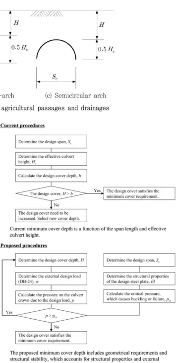
(a) Round pipe (b) Pipe-arch (c) Semicircular arch Fig. 2 General shapes of culverts used for agricultural passages and drainages
between the cover depth, span length, and material pro- perties.
The current and proposed procedures to determine the minimum cover depth are summarized in Fig. 3 and the difference between the current minimum cover and proposed one is briefly discussed. For the most part, the proposed procedure is very different from the current procedure.
As discussed earlier, however, current method to calculate minimum cover depth has some weak points, which need to be addressed. The proposed procedure is developed by considering geometrical requirements, structural pro- perties, external design dead and live loads, and structural safety. The basic features of the proposed procedure are summarized below.
Generally, the external live load effect on the culvert increases as the cover H decreases. If H is very shallow, the surface live load can cause excessive deflection, buckling, or severe damage of the culvert. Therefore, determination of minimum depth of cover is very important.
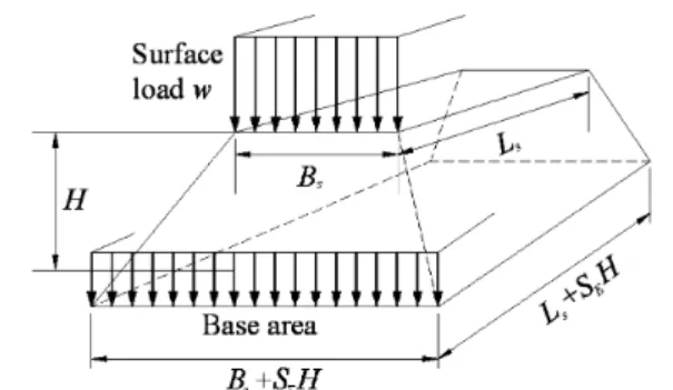
The surface live load is transferred to the culvert through pavement and soil. The effect of live load on the culvert is based on the truncated pyramid model as shown in Fig. 4. The procedures for the calculation of live load pressure on the culvert are based on the assumption that soil is elastic. The surface load (w) represents a tire contact area of width Bs and length Ls. SE is the spreading factor, and is equal to 1.75 for AASHTO SSHB and 1.15 for AASHTO LRFD (2007) where the cover depth is 0.6 m or greater. The truncated pressure on the culvert due to the tire contact pressure is
Fig. 3 Current and proposed flow chart to determine the required minimum cover depth
(3)
where Bs is 200 mm and Ls is 500 mm for the Ministry
of Land Transport and Maritime Affairs (MLTM, 2005)
standard DB-24 vehicle. If w is known and the critical
pressure which causes local buckling or excessive deflection
Fig. 4 Truncated pyramid showing how a surface load (w) spreads over a base area at cover depth (H)
of the culvert can be evaluated, the minimum cover depth can be found by solving Equation (3). Thus, the minimum cover can be defined as the cover depth of a safe and stable culvert system subjected to a large number of passes of external live load.
The critical location in a culvert where the maximum deflection or maximum moment develops due to external loads is generally near the crown. Tests to failure of corrugated steel culverts show that static loads over the crown can be many times greater than the load on one side (Watkins and Anderson, 1999). In order to find the critical pressure near the crown, some researchers (Timoshenko and Gere, 1961; Moore, 1989) investigated when and where the buckling happens. If a parabolic arch structure is subjected to a uniform load (q) distributed along its span as shown in Fig. 5, there will be axial compression but no bending in the arch. If the intensity of the uniform load is increased, the arch starts to buckle at a critical load (q
cr), which can be calculated from Equation (4) (Timoshenko and Gere, 1961).
(4)
where E is the elastic modulus, I is moment of inertia, and γ
4is the numerical factor depending on the ratio
, where S
cis the culvert span and H
cis the height of the arch. Generally, the top part of pipe-arches is
(a) (b)
Fig. 5 A parabolic arch with hinged supports subjected to a uniform load
similar to a half circle. In this study, it is assumed that the shape of pipe-arch is a half circle, and each corner of the circle has a fixed support where γ
4is 97.4 (see Fig. 5(b)).
Once the culvert design is completed, q
crin Equation (4) can be calculated because γ
4, S
c, E and I are known.
If the maximum pressure (q) on the crown due to dead and live load can be determined for a given cover depth, and the calculated pressure can be compared to q
crto decide whether the design cover depth is adequate. If the calculated q is larger than q
cr, the design cover depth is not sufficient to support the design load. Then, either the design cover needs to be increased to support the design load, or the design live load needs to be reduced until q is smaller than q
cr.
The previous sections show that if q is lower than q
cr, the design cover depth satisfies the minimum cover requirement for the load rating evaluation. Thus, the minimum cover (h) to carry the design live load over the culvert can be determined by setting q equal to q
cr. In order to determine h, there can be many variables to be considered. The variables include the span length, culvert height, thickness or corrugated steel plate, and dead and live load. In practice, the culvert geometry is typically selected from the standard layouts. Standard culvert sizes are frequently used in most designs. The standard detail layouts of pipe-arches are listed in Table 1 (AISI, 1994).
In this study, the standard DB-24 design truck is used
as the external live load. The dead load is considered
as the soil weight over the culvert crown. The appropriate
load factors for dead and live load are used to ensure
the safety and usability of culvert. The pressure on the
Dimensions Waterway area,
(m
2)
Layout dimensions Span, S
c(m)
Height, H
c(m)
B (m)
R
t(m)
R
b(m)
3.12 2.06 5.11 0.61 1.56 4.53
3.25 2.11 5.39 0.66 1.65 3.89
3.33 2.16 5.67 0.64 1.67 4.58
3.48 2.21 5.95 0.70 1.76 4.01
3.53 2.26 6.22 0.67 1.78 4.65
3.61 2.31 6.60 0.64 1.81 5.50
3.76 2.36 6.87 0.70 1.90 4.74
3.81 2.41 7.25 0.67 1.92 5.51
3.86 2.46 7.53 0.64 1.94 6.54
3.91 2.54 7.90 0.61 1.96 7.99
4.09 2.57 8.27 0.67 2.05 6.47
4.24 2.62 8.64 0.73 2.14 5.61
4.29 2.67 9.01 0.70 2.16 6.46
4.34 2.72 9.38 00.67 2.18 7.56
4.52 2.77 9.75 0.73 2.28 6.46
4.67 2.82 10.13 0.80 2.37 5.76
4.72 2.87 10.50 0.77 2.39 6.50
4.78 2.92 10.96 0.73 2.40 7.40
4.83 3.00 11.33 0.70 2.43 8.59
5.00 3.02 11.71 0.76 2.52 7.39
5.05 3.07 12.17 0.73 2.54 8.45
crown due to the dead and live load is calculated from the following equation by modifying Equation (3).
(5)
where γ
sis the soil density, H is the clear cover above the crown, W is the surface load, and φ
Dand φ
Lare load factors for dead and live load, respectively. The pressure on the crown is also a function of cover depth.
KEC minimum cover may not be applicable to the struc- tures damaged due to steel corrosion. Generally, the plate thickness of these culverts becomes thinner due to section loss and pitting. Many researchers (Bellair and Ewing, 1984; Potter et al., 1991; NCHRP 254, 1998) have reported culvert failure and damage caused by metal loss associated with corrosion and related degradation. The corroded part of steel plate turns to rust. Rust cannot resist external loads because it is not strong enough. It is questionable if a culvert with the minimum cover can support the external load after its plate thickness is reduced significantly. Thus, the minimum cover require- ments should include geometric and structural properties associated with damage to ensure durability and safety of the culvert during its service life. In this study, section loss of culvert plate will be considered in minimum cover calculations.
Potter et al. (1991) reported that most of metal loss due to corrosion occurs at the waterside in culvert.
Although side and bottom plates are usually thicker than
top plates, it is typically assumed for the design that
culverts are fabricated with plates with the same thick-
ness. The thinnest plate used in the culvert governs the
design calculations. Degler et al. (1988) investigated about
900 corrugated metal pipe-arch structures in Ohio to
identify and determine the cause of numerous problems
observed with these structures. According to their research,
only a very few culverts (about 0.2 %) among 900 culverts
experienced major cracking on seam areas and severe
steel plate damage due to corrosion, and steel plate con-
dition of most culverts (about 99.6 %) was better than
the generally fair condition. Usually, culverts were removed,
replaced or repaired before plate damage was reached
to the poor condition. Thus, in this study, it is assumed
that the poor condition corresponding to 50% reduction
in steel plate flexural strength (EI). Factors used in the
calculations are γ
s= 18.85 kN/m
3, γ
4= 97.4, φ
D= 1.25 and
φ
L= 1.75. The standard DB-24 load is used to calculate
the surface load (W = 376.58 kN). The proposed minimum
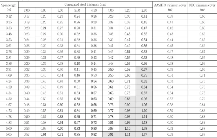
cover is calculated and the results are listed in Table 2.
Table 2 The proposed minimum covers in meter for the standard culverts with different gauge numbers