PEMFC 바이폴라 플레이트 제조용 EPOXY/GRAPHITE/EXPANDED GRAPHITE 복합재료의 열경화 및 전기적 성질
이재영*, 이홍기*†
*우석대학교 수소연료전지 부품 및 응용기술 지역혁신센터
Thermal Curing and Electrical Properties of Epoxy/Graphite/Expanded Graphite Composite for
Bipolar Plate of Pemfc
JAEYOUNG LEE*, HONGKI LEE*†
*Hydrogen Fuel Cell Parts and Applied Technology RIC, Woosuk University, Wanju, Jeonbuk 565-902, Korea
ABSTRACT
Epoxy/graphite/expanded graphite composites have been prepared in various weight ratios and thermal degradation and electrical properties were estimated in order to use for the bipolar plate materials in PEMFC.
Thermogravimetric analysis (TGA) showed that the epoxy/graphite system cured by a curing agent GX-533 was most proper because its weight loss until 80℃ at which PEMFC would be operated was 0.3 wt%, and differential scanning calorimetry (DSC) analysis showed its cure temperature would be sufficient at 80℃.
The activation energy for the cure reaction was 132.0 kJ/mol and the pre-exponential factor was 1.76×10¹⁷min-1. Electrical conductivity on the surface of the bipolar plate prepared under a pressure of 200 kgf/cm2 was increased from 4 to 25 S/cm2 by increasing expanded graphite (EG) content from 50 phr to 90 phr. The percolation threshold was initiated around 75 phr and the corrosion rate at 80 phr was 1.903 uA/cm2.
KEY WORDS : PEMFC(고분자 전해질 연료전지), Bipolar plate(바이폴라 플레이트), Composite(복합 재료), Epoxy resin(에폭시 수지), Expanded graphite(팽창 흑연)
†Corresponding author : [email protected]
[ 접수일 : 2011.11.28 수정일 : 2011.12.3 게재확정일 : 2011.12.27 ]
1. Introduction
Polymer electrolyte membrane fuel cell (PEMFC) has been expected as a major alternative energy
source for electrical vehicles and stationary power generations in the near future. Therefore many researchers and companies have investigated to increase the power density and now it has been close to being meet. So the focus of PEMFC R&D is shifting to the development of new materials or the improvement of the existing materials for the
parts of electrolyte membrane, gas diffusion layer (GDL), catalyst, bipolar plate, electrodes, etc. at lower price with higher performance1-3). For these purposes, bipolar plate could be the first target because it accounts for more than 80 wt% of the whole stack and 30% of the cost4).
Bipolar plate is a repeated unit together with two GDLs and a membrane electrode assembly (MEA) separating the adjacent cell in a PEMFC stack. The main function of the bipolar plate is to supply hydrogen fuel and oxidant gas (oxygen or air) to anode and cathode electrodes, respectively through flow channels, which are also acted as water drainage, and another main function is to conduct the electrons generated from the hydrogen oxidation reaction at the anode-side. Therefore it should be required to satisfy the good electrical conductivity over 100 S/cm. It should also have good mechanical stability, corrosion resistance and low gas per- meability5-7). To achieve these properties together with cost reduction and easy processibility, metallic materials or polymer/graphite composites have been used to substitute the conventional graphite raw material because graphite plate is so brittle and its manufacturing cost is too high5).
Metallic bipolar plates are made of stainless steel coated with high corrosion-resistant and electrically conductive materials such as titanium, nickel nitride, chromium nitride, nickel carbide, chromium carbide, etc. Therefore they can perform the excellent mechanical strength, high electrical conductivity and low gas permeability, however they also have some fatal defects in the corrosion resistance regardless of protective coatings because pinhole problems take place during the coating process and microcracks grow on the surface coatings under the harsh operating condition of high relative humidity (over 90%), high acidity (pH 2~3) and high temperature (60~80℃).The
core metals are dissolved out in the form of metal ions and oxides through the pin holes and micro- cracks, and the dissolved metal ions diffuse into the electrolyte membrane and then are trapped on the ion exchange sites so that the ionic conductivity is lowered8).
Graphite raw materials have enough electrical conductivity to be used for bipolar plate purposes.
They also exhibit far better corrosion resistance and lower density than those of the metallic materials9). But the graphite bipolar plates are too brittle to achieve good mechanical properties and the channel machining process on the plate surface is needed, which is a costly and time consuming step. To overcome the demerits of graphite bipolar plate, conductive carbons are composited with a polymer matrix. Then, the composites can meet the requirements of low cost, high flexibility and light weight as well as good electrical conductivity.
The gas flow channels can also be formed directly on the surface of the plate during moulding processes without any post process10-12). There are various kinds of conductive carbon compounds such as graphite powders and fibers, expanded graphites (EG), carbon blacks, and carbon nanotubes (CNT), and there are various kinds of polymer matrixes such as polyethylenes (PE), polypropylenes (PP), polyphenylene sulphides (PPS), epoxy resins, phenolic resins, polyesters, etc. The first three are thermoplastics and the last three are thermosets13). In this study, thermogravimetric analysis (TGA) was carried out in order to the thermal stability of bipolar plates made of various compositions of epoxy/graphite/ expanded graphite (EG) because thermally decomposed small molecules were acted as impurities on the Pt catalyst surface. And cure kinetics was studied by differential scanning calorimetry (DSC) in order to calculate kinetic parameters, which could be used to estimate the
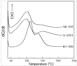
Fig. 1 DSC curves for epoxy/graphite (35 phr) with each curing agent at a heating rate of 10 ℃/min
curing time at a selected temperature. The effect of EG on the electrical conductivity and corrosion resistance were also studied.
2. Experiment
A bisphenol A type epoxy base resin (YD-128), two polyamide type curing agents (G-0331 and GX-533), one modified amine type curing agent (KH-500) and a catalyst (K-54) were supplied by Kukdo Chemical Co. Ltd. A graphite and an EG powders were purchased from Timcal Ltd. The grade of the graphite was TIMREX®KS150 and that of the EG was TIMREX®BNB90.
YD-128 was mixed with a graphite (35 phr) and/or an EG (50~85 phr) powders with different composition homogeneously, and G-0311 (50 phr) or GX-533 (53 phr) or KH-500 (37 phr) together with K-54 (3 phr) and a drop of an antifoaming agent were poured into the epoxy/graphite compounds and mixed thoroughly, in which phr meant part per one hundred epoxy resin. Micro bubbles were removed from the mixtures in a vacuum oven for 10 min and the mixture was poured into a bipolar plate mould having gas flow channels. Finally it was positioned on the hot-press apparatus (25-12H, CARBER, USA) and cured at 80℃ (for G-0331 and GX-533) or 120℃ (for KH-500) under 100 or 200 kgf/cm2 pressure for 2hr.
To study the thermal stability, TGA was carried out by using a thermal analysis system (TG/DTA 6200, EXTRA 6000 series, Seiko Instruments Inc., Japan). 5 mg of each cured sample was positioned into the TGA furnace and dynamic run was per- formed from room temperature to 600℃ at the heating rate of 10 ℃/min. It was done under a nitrogen atmosphere of 200 ml/min to prevent the oxidation of the sample. The sensitivity of the TGA was 0.2 μg, and thus the minimum content
was measured to be 0.004 wt% of the 5mg sample.
Differential scanning calorimetry (DSC) data was obtained by using DSC Infinity Series (In- strumental Specialists Inc., USA). Dynamic DSC analysis was carried out as follows: the aluminum pan containing 3~4 mg of the uncured epoxy mixture was placed in the DSC furnace and it was heated according to the program of constant heating rate from room temperature to 300℃. The heating rates were 5, 10, 15 and 20 ℃/min under nitrogen purge gas of 50 ml/min.
The in-plane conductivity was measured with Keithley 2000 conductivity meter, and Potentiostat/
Galvanostat (EG&G PARC Model 273A) was used to measure the corrosion behaviour in 1M-H2SO4.
3. Results and discussion
To decide the cure condition for the epoxy/
graphite (35 phr) systems with three curing agents, the exothermic heat generated during the cure reaction was analyzed by DSC instrument at a heating rate of 10 ℃/min and the data were displayed in Fig. 1. When the system was cured
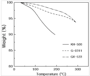
Fig. 2 TGA curves for epoxy/graphite (35 phr) with each curing agent at a heating rate of 10 ℃/min
with polyamide type curing agents (G-0331 or GX-533), the exothermic heat started to appear at about 50℃ and increased rapidly until about 100℃, then it decreased. These results meant that two systems have similar curing patterns at the same temperature range except the small peak at about 155℃ in G-0311 system. However, the system cured with the modified amine type (KH-500) showed two exothermic peaks. The first exothermic heat started at 59℃ and increased slowly until about 85℃, and then it steeply increased until 112℃, and the second peak was shown at 135℃. These peaks could be explained by the two mechanisms in epoxy/amine curing systems: the former was due to the heat of reaction between epoxy and amine groups, and the second peak was owing to the heat of reaction between epoxy and self-generated hydroxyl groups14,15). From these results, the cure temperature for G-0331 and GX-533 would be sufficient at 80℃
and that for KH-500 be 120℃.
Thermal stability at the working temperature of a bipolar plate is a very important factor to get successful assembly of a fuel cell stack. It was estimated by TGA analysis for the cured epoxy/
graphite (35 phr) system with each curing agent and the TGA curves were shown in Fig. 2. The residual weight at 80℃, which corresponded to PEMFC working temperature, for the bipolar plates cured with GX-533, G-0331 and KH-500 were 99.7, 99.1 and 98.2 wt%, respectively. These meant that the epoxy/graphite composite cured by GX-533 was most stable in the working temperature, and it was much clear by comparing the residual weight of each systems at 200℃, that is, 97.5, 96.2, and 89.4 wt% for GX-533, G-0331 and KH-500, respectively. From these results, the epoxy/graphite system cured by GX-533 was most proper as a bipolar plate material, therefore
the GX-533 system would be used to study cure kinetics and corrosion resistance hereafter.
In order to calculate the cure time to be fully reacted at a sellected temperature, the reaction kinetics of epoxy/graphite (35 phr) composite cured by GX-533 was investigated by DSC at various heating rates and the DSC data were introduced to Kissinger equation with the as- sumption that the epoxy cure reaction took place in the first order15), which would provide the kinetic parameters such as activation energy and pre-exponential factor. Kissinger equation is ex- pressed as the following:
-ln(q/TP2)=Ea/RTP - ln(AR/Ea) (1)
where, q is heating rate, TP is temperature at a peak in which dQ/dt value is maximum, Ea is cure activation energy, A is pre-exponential factor, and R is the universal gas constant. This method gives a relatively accurate activation energy and pre-exponential factor by calculating the relationship between 1/TP and -ln(q/TP2
).
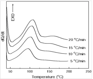
Fig. 3 showed the DSC curves for the system
Fig. 3 DSC curves for epoxy/graphite (35 phr) with GX-533 at various heating rates
Table 1 Cure kinetic parameters for epoxy/graphite (35 phr) with GX-533
q (℃/min)
Tp (K) 1/Tp×103 (K-1)
-ln(q/Tp2) Ea
(kJ/mol) A×1017 (min-1) 5
10 15 20
368.72 374.98 378.35 380.74
2.71 2.67 2.64 2.63
10.21 9.55 9.16 8.89
132.0 1.76
Fig. 4 Kissinger plot of 1/TP vs. –ln(q/TP2
) for epoxy/graphite (35 phr) with GX-533
cured by GX-533 at various heating rates. The curves had a large exothermic peak together with a very weak one, and the weak one became biggered with the increasing heating rate. The large one displayed between 50~125℃ implied that almost all functional groups reacted in one stage via amide-epoxy and hydroxyl-epoxy reactions, however at high heating rate, there was insufficient time to be fully cured at the first stage so some hydroxyl-epoxy reaction occurred at around 150℃16). The graphite powder maybe acted as just a filler without any influence on the cure reaction.
To get the kinetic parameters, TP value at each heating rate, q was obtained from the DSC curves and they were listed in Table 1. The data of the third and fourth columns were introduced to Kissinger equation and relationship between 1/TP
and -ln(q/TP2) was plotted in Fig. 4. The linear plot was expressed by the following equation:
-ln(q/TP2)=15.89 ×103/TP - 32.85 (2) And it was found that the activation energy, 132.0
kJ/mol was calculated from the slope and the pre-exponential factor, 1.76×10¹⁷ min-1 was obtained from the y-intersect as was shown in Table 1.
These kinetic parameters were introduced to Arrhenius equation (Eq.3)17) in order to get cure rate constant, k at a selected temperature, T so that the time needed for the full curing of an epoxy system could be calculated at the selected temperature.
k =A exp(-Ea/RT) (3)
Effect of EG content and compression moulding pressure on the conductivity of epoxy/graphite/EG composites was shown in Fig. 5. Electrical con-
Fig. 5 Effect of EG content and moulding pressure on the conductivity of epoxy/graphite system, where graphite was fixed to 35 phr
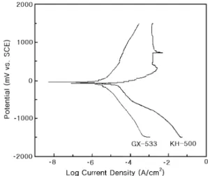
Fig. 6 Polarization curves epoxy/graphite (35 phr)/EG (80 phr) systems
ductivity on the bipolar plate surface prepared compression moulding of 200 kgf/cm2 increased with the increasing EG content from 4 to 25 S/cm2, and abrupt increase was found after 70 phr of EG. It was caused by the formation of conductive pathway, which meant the percolation thresholds was shown around 75 phr of EG. Fig.
5 also showed that as the moulding pressure became twice, electrical conductivity was shifted to upward direction in all EG contents. It was due to the much shorter distance between the con- ductive particles offering much easier electron pathes.
The electrical stability of the obtained bipolar plate could be confirmed by estimating the corrosion resistance, which could be obtained from the polarisation curves. It was measured at 1M-H2SO4
solution with the scan rate of 1 mV/s and the curves for epoxy/graphite (35 phr)/EG (80 phr) composites cured by GX-533 and KH-500 were shown in Fig. 6. The corrosion rate for KH-500 was 19.72 uA/cm2 and that for GX-533 was 1.903 uA/cm2. The latter was 10 times lower than the
former despite of no difference except the type of curing agent. It was maybe because the corrosion resistance of the epoxy system cured by polyamide type GX-533 was higher than that of the system with amine type KH-500. So the bipolar plate made from epoxy/graphite/EG system cured by GX-533 showed excellent corrosion resistance.
4. Conclusions
Thermal stability and cure condition for bipolar plate made from various compositions of epoxy/
graphite/EG system were investigated and the electrical conductivity and corrosion resistance were also studied. TGA analysis showed that the epoxy/graphite (35 phr) system cured by GX-533 was most proper as a bipolar plate material because the residual weight at 80℃, a working temperature of PEMFC was 99.7 wt% with very low weight loss. The cure reaction between amide/
epoxy and hydroxyl/epoxy groups occurred at one stage of 50~125℃ and DSC curve said that its cure temperature at 80oC would be sufficient.
The activation energy for the cure reaction was 132.0 kJ/mol and the pre-exponential factor was 1.76×10¹⁷min-1, which was calculated from Kissinger equation. Electrical conductivity on the bipolar plate surface was increased with the increasing EG content and the value was 25 S/cm2 when EG content was 85 phr. The excellent corrosion re- sistance was shown in the system with 80 phr of EG giving the corrosion rate of 1.903 uA/cm2. Therefore, epoxy/graphite (35 phr)/EG (80 phr) systems cured with GX-533 could be used as polymer composite for bipolar materials.
Acknowledgement
This work was supported by the RIC program of MKE (2011) and Woosuk University (2011).
References
1) F. A. de Bruijn, V. A. T. Dam1 and G. J. M.
Janssen, “Durability and Degradation Issues of PEM Fuel Cell Components”, Fuel Cells, Vol.
8, No. 1, 2008, p. 3.
2) Arnd Garsuch, D. A. Stevens, R. J. Sanderson, S. Wang, R. T. Atanasoski, S. Hendricks, M.
K. Debe, and J. R. Dahna, “Alternative Catalyst Supports Deposited on Nanostructured Thin Films for Proton Exchange Membrane Fuel Cells”, J. Electrochem. Soc. Vol. 157, No.2, 2010, p. B187.
3) Y. D. Lim, D. W. Seo, H. C. Lee, H. M. Jin, MD. Awlad Hossain, I. S. Jeong and W. G.
Kim, “Preparation and Properties of Sulfonated Poly(ether Sulfone)s Containing BFBN for PEMFC”, Trans. of the Korean Hydrogen and New Energy Society, Vol. 22, No. 5, 2011, p.
579.
4) L. Peng, D. Liu, P. Hu, X. Lai and J. Ni,
“Fabrication of Metallic Bipolar Plates for Proton Exchange Membrane Fuel Cell by Flexible Forming Process-Numerical Simulations and Experiments”, J. Fuel Cell Sci. Technol., Vol. 7, 2010, p. 031009.
5) B. Cunningham and D. G. Baird, “The Devel- opment of Economical Bipolar Plates for Fuel Cells”, J. Mater. Chem., Vol. 16, 2006, p. 4385.
6) A. J. Appleby and F. R. Foulkes, “Fuel Cell Hand Book”, Van Nostrand Reinhold, New York, 1989.
7) E. Rasten, G. Hagen and R. Tunold, “Electrocatalysis in Water Electrolysis with Solid Polymer Elec- trolyte”, Electrochim. Acta, Vol. 48, 2003, p.
3945.
8) V. Mehta and J. S. Cooper, “Review and Analysis of PEM Fuel Cell Design and Manu- facturing”, J. Power Sources, Vol. 144, 2003, p.
32.
9) G. O. Mepsted and J. M. Moore, “Handbook of Fuel Cells - Fundamentals Technology and Appli- cations”, John Wiley & Sons, Ltd., 2003, pp.
286-293.
10) B. D. Cunningham, J. Huang and D. G. Baird,
“Development of Bipolar Plates for Fuel Cells from Graphite Filled Wet-lay Material and a Thermoplastic Laminate Skin Layer”, J. Power Sources, Vol. 165, 2007, p. 764.
11) E. A. Cho, U. S. Jeon, H. Y. Ha, S. A. Hong and I. H. Oh, “Characteristics of Composite Bipolar Plates for Polymer Electrolyte Membrane Fuel Cells”, J. Power Sources, Vol. 178, 2004, p. 178.
12) H. S. Lee, H. J. Kim, S. G. Kim and S. H. Ahn,
“Evaluation of Graphite Composite Bipolar Plate for PEM (Proton Exchange Membrane) Fuel Cell: Electrical, Mechanical, and Moulding Pro- perties”, J. Mater. Process. Technology, Vol.
187-188, 2007, p. 425.
13) A. Heinzel, F. Mahlendorf and C. Jansen, “The Encyclopedia of Electrochemical Power Sources”, Elsevier, 2009, pp. 810-8169.
14) C. C. Riccardi, H. E. Adabbo and R. J. J.
Williams, “Curing Reaction of Epoxy Resins with Diamines”, J. Appl. Polym. Sci., Vol. 29, 1984, p. 2481.
15) J. Y. Lee, M. J. Shim and S. W. Kim, “Synthesis of Liquid Crystalline Epoxy and Its Mechanical and Electrical Characteristics - Curing Reaction of LCE with Diamines by DSC Analysis”, J.
Appl. Polym. Sci., Vol. 83, 2002, p. 2419.
16) C. S. Chern and G. W. Poehlein, “A Kinetic Model for Curing Reaction of Epoxides with Amines”, Polym. Eng. Sci., Vol. 27, 1987, p.
788.
17) J. Y. Lee, M. J. Shim and S. W. Kim, “Effect of MDA-endcapped CTBN on the cure kinetics of epoxy system by autocatalytic cure rate expression”, J. Mater. Sci., Vol. 35, 2000, p.
3529.