Micro Valve with Functional Actuator
Sonam Yun, Young-Bog Ham, Kyung-Woo Lee and Kunio Kanda
기능성 액츄에이터를 이용한 마이크로 밸브
윤소남†
․
함영복*․
이경우**․
칸다 쿠니오***Key Words: Piezoelectric Element(압전소자), PZT Actuator(압전 액츄에이터), Directional Control Valve(방향제어밸브)
Abstract
Piezoelectric(PZT) actuator can substitute for solenoid which is used in fluid control field because it has faster response times and no possibility of explosion. Besides, it is available in a high temperature and it has low energy consumption.
In this study, pneumatic micro valve, bimorph type PZT actuator using the softner type PZT, carbon plate as a shim and its controller circuit were suggested and investigated. Performance tests and characteristics analysis, such as displacement, force, hysteresis and frequency properties, were carried out. The displacement of the actuator measured at the end point was 63 ㎛, force of the actuator was 0.052 N and maximum operating frequency was 15Hz. Also, characteristics of the micro valve with PZT actuator were evaluated in a testing system. The results show that the suggested PZT actuator is suitable for micro valve.
†한국기계연구원, 첨단산업기술연구부
E-mail : [email protected]
TEL : (042)868-7155 FAX : (042)868-7176
* 한국기계연구원, 첨단산업기술연구부
** 경원훼라이트공업, 기술연구소
*** Ceramic-Servo Institute, Japan
Nomenclature
: Piezoelectric constant [m/V]
: Maximum force of cantilever [N]
: Resonance frequency of cantilever [Hz]
: No load maximum deflection [m]
: Cantilever length [m]
: Residual pressure of reservoir [Pa]
: Initial pressure of reservoir [Pa]
: Elastic constant of piezo material [㎡/N]
: Absolute temperature of room [°K]
: Cantilever thickness [m]
: Discharge time of air[s]
: Inner volume of reservoir [㎥]
: Input voltage [V],
: Cantilever width [m]
: Density of piezo materials [kg/㎥]
1. Introduction
The application of piezoelectric characteristics which has a history of a century plays a core role in nano manufacturing and nano position control in a nano technical field and lots of researches are being performed connected with information storing technology, nano printing technology and ink jet printing technology
1~2).
Piezoelectric (PZT) actuator can substitute for
solenoid which is used in fluid control field
because it has faster response times and no possibility of explosion. Besides, it is available in a high temperature (over 80℃) and it has low energy consumption
3~4). Owing to these benefits, the researches of applying PZT actuator to simple on-off nozzle flapper valve
5)as well as proportional valve
6)are being performed. Also there is a brisk research about high speed valve
7).
This study is basic research for applying PZT actuator to fluid control valve and for developing new control method. So pilot valve, 2 stage and 3 stage pneumatic control valve which are composed of PZT actuator have been designed. And this study investigated characteristics of PZT valve through experimental apparatus and it was confirmed that PZT valve is able to be applied as pilot that makes energy saving and fast response improvement possible.
2. Design of PZT valve
2.1 Design of PZT actuator
The PZT actuator is a bimorph type. If an electric voltage is given to the piezo ceramics, deformation displacement occurs. This property can enable pressure control, flow control and direction control by applying to fluid control valve.
This characteristics can be predicted by following numerical formula
8).
h = 3
2 d
31× l
2t
2V (1)
F
b= 2⋅w⋅t l
d
31S
11V (2)
f
r= 0.158 t l
2ρS 1
11(3)
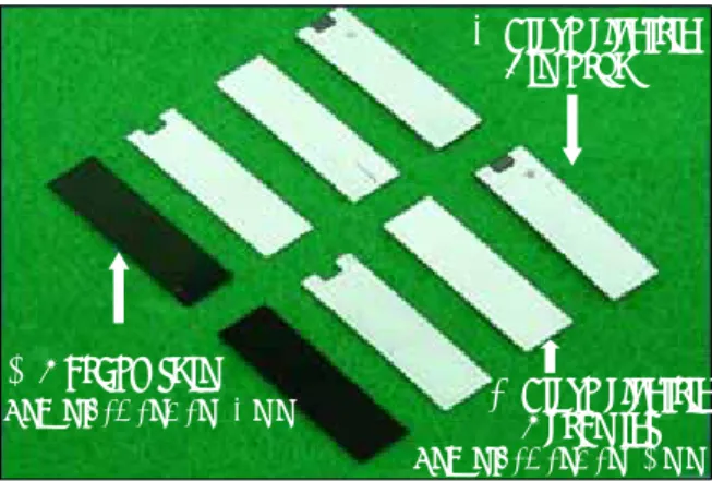
Fig. 1 shows parts of the bimorph PZT actuator which is designed and produced in this study. The length of the carbon shim is 25.2 mm, the width 7.2 mm, and the thickness 0.5 mm. The thickness of the piezo ceramic layer is 0.1 mm. The piezoelectric constant of these piezo ceramics materials is 220×10
-12[C/N] and the density of the materials is 7.5×10
3[kg/㎥].
1. Carbon shim
2. Piezo electric Ceramics 3. Piezo electric Bimorph
LxWxt=25.2x7.2x0.1 mm LxWxt=25.2x7.2x0.3 mm
Fig. 1 Prototype PZT actuator 2.2 Design of PZT valve assembly
Fig. 2 and Fig. 3 show the inner structure and appearance of 2 stage and 3 stage valve which were designed and produced in this study. The orifice of PZT actuator part was designed so that the maximum use pressure became 10 bar and limited the maximum displacement to within 25
㎛ in order to be able to get dynamic characteristics at 15 Hz.
PZT actuator controller
Upper orifice Lower orifice
PZT actuator
Cushion part
Directional control valve
Inlet Outlet
Fig. 2 2 stage pneumatic valve assembly with
PZT actuator
Fig. 3 3 stage pneumatic valve assembly
Cushion device was set up in order to supply a PZT actuator department with stable pressure in Fig. 2. In Fig. 3, the valve was designed and produced which has 5 ports and bidirectional operation is possible, flow is 500 lpm and effective area is 7 ㎟. A numerical formula used in effective area calculation is as follows
9).
Q = 11.1×S
e×( P
1+ 1.033) 273
T (4)
Here, Q: Air flow [㎥/s], S
e: Valve effective area [㎟], P
1: Input pressure [Pa]
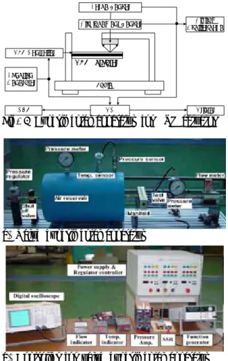
2.3 Experimental apparatus and method
The characteristics of the PZT actuator and the PZT valve, which was designed and produced in this study, were examined using the experimental apparatus shown in Fig. 4 and Fig. 5. The PZT actuator characteristics like displacement and force step response, and frequency response with rectangle wave are measured with the experimental apparatus shown in Fig. 4. The measurements are performed using the function generator, A/D converter and personal computer. Also, the pneumatic valve characteristics are measured with the apparatus shown in Fig. 5.
Table PZT Actuator
Displacement Sensor Digital
Oscilloscope
PC Printer
CRT PZT Controller
Function Generator
Force Sensor
Fig. 4 Experimental apparatus for PZT actuator
a) Valve experimental apparatus
b) Controller for valve experimental apparatus
Fig. 5 Experimental apparatus for pneumatic valve using PZT actuator
3. Results and discussion
3.1 PZT actuator experimental results
Fig. 6 shows displacement characteristics of PZT actuator which was designed and manufactured in this study. It was confirmed that maximum displacement is 63 ㎛ and some chattering is occurring in last point of displacement.
Fig. 7 shows a force characteristics of a PZT actuator. It is verified that it obtains about 0.052 N as a result of conversion and this means that approximately 0.2 mm orifice is needed to overcome pneumatic pressure of 10 bar.
The characteristics of repeated rectangle waves of
PZT actuator are obtained to know the response at
high frequency. Fig. 8 shows the rectangle wave
obtained at 15 Hz and the gain is -9 dB. This
result shows, that the designed PZT actuator is
better than existing solenoid valve which have characteristics of 10 Hz and below. It can be confirmed that this actuator can substitute the existing actuator in the respect of energy saving effects.
0 1 2 3 4 5
-0.15 -0.14 -0.13 -0.12 -0.11 -0.10 -0.09 -0.08 -0.07 -0.06 -0.05 -0.04 -0.03 -0.02 -0.01 0.00 0.01
Input Signal Displacement
30 25 20 15 10 5 0
Input Signal [ V ]
Time [ sec ]
63 um
Displacement [mm]Displacement [mm]
Input signal [V]
Time [s]
Fig. 6 Displacement characteristics of PZT actuator
Fig. 7 Force characteristics of PZT actuator
0.0 0.2 0.4 0.6 0.8 1.0
0 5 10 15 20 25
0.0 0.2 0.4 0.6 0.8 1.0
0.050 0.055 0.060 0.065 0.070 0.075
Input Signal [V]
Time [s]
Displacement Input Signal
Displacement [mm]
Fig. 8 Rectangle wave frequency characteristics of PZT actuator
3.2 PZT valve assembly experimental results In this paragraph, the experimental property of 2
stage and 3 stage valve which include piezo actuator is considered.
3.2.1 2 stage valve experimental results
According to experiment results of flow characteristics of 2 stage valve, the effective area of the valve is confirmed to 2.0 ㎟.
This result comes from following formula (5) by using pressure which is obtained from experimental apparatus of Fig. 5. This is larger than 1.5 ㎟ that are effective area range to request to standard
10~11). S
e= ( 12.9V
rt 1
alog
10P P + 1.03
o+ 1.03 ) 273 T (5)
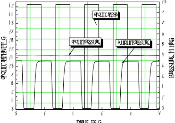
Fig. 9 shows pressure step response results when inlet pressure is 5 bar. As a result, time constant of pressure step response is confirmed to 74 ms.
Also, as a result of having examined a response with a way to measure outlet pressure while inputting rectangle wave repeatedly, it was confirmed that manufactured 2 stage PZT valve operates at 10 Hz and over.
0 1 2 3 4
0 2 4 6 8 10 12 14 16 18 20 22 24
Input Signal
Input Pressure
Output Pressure
Pressure[bar]
Input Signal[V]
Time[s]
0 1 2 3 4 5 6
ms
= 74
τ0 1 2 3 4
0 2 4 6 8 10 12 14 16 18 20 22 24
Input Signal
Input Pressure
Output Pressure
Pressure[bar]
Input Signal[V]
Time[s]
0 1 2 3 4 5 6
ms
= 74
τFig. 9 Step response characteristics of 2 stage valve assembly
3.2.2 3 stage valve assembly experimental results The effective area of 3 stage valve was confirmed to 6.89 ㎟ in consequence of flow characteristics experiment. The time constant of pressure step response is 85 ms as shown in Fig.
10. The experiment was carried out with the same
method used in 3.2.1. Also, the experiment of
rectangle wave repeatability of 3 stage valve was
carried out a way to be same as 2 stage valve
assembly, and it was operating enough in 7 Hz.
0 1 2 3 4 5
0 1 2 3 4 5 6 7 8 9 10 Input Signal
Output Pressure Input Pressure
Pressure [ bar ]
Time [ s ] 0
2 4 6 8 10 12 14 16 18 20 22 24
Input Signal [ V ]
Fig. 10 Step response characteristics of 3 stage valve assembly
4. Conclusion
In this study, as a basic research to provide a PZT actuator to a fluid control valve, a PZT actuator was made and experiments are carried out.
A manufactured PZT actuator was applied to 3-2 way pneumatic control valve and characteristics were examined experimentally.
The result of this study can be summarized as following;
1) The PZT actuator consists of a carbon shim with 25.2 mm length, 7.2 mm width, 0.3 mm thickness and the piezo ceramics have 0.1 mm thickness. From the PZT actuator experiment, it is confirmed that its rectangle wave repeatability is 15 Hz at -9 dB.
2) The time constant for the 3/2 method pneumatic control valve with a PZT actuator was confirmed to be 74 ms or below.
3) The PZT actuator developed in this work showed a faster response time and lower energy consumption than those of existing solenoid valves.
References